Table of Contents

Related Manuals for Fluke 381


Summary of Contents for Fluke 381
- Page 1 Remote Display True-rms Clamp Meter Calibration Manual December 2010 Rev.1, 6/12 © 2010-2012 Fluke Corporation. All rights reserved. Specifications are subject to change without notice. All product names are trademarks of their respective companies.
- Page 2 Fluke authorized resellers shall extend this warranty on new and unused products to end-user customers only but have no authority to extend a greater or different warranty on behalf of Fluke. Warranty support is available only if product is purchased through a Fluke authorized sales outlet or Buyer has paid the applicable international price.
-
Page 3: Table Of Contents
Table of Contents Title Page Introduction ......................1 Contact Fluke ..................... 1 Safety Information ..................... 2 The Meter ......................5 Specifications ..................... 5 Electrical Specifications ................5 Mechanical Specifications ................7 Environmental Specifications ................ 7 Required Equipment ..................8 Performance Tests ....................8 Calibration Adjustment .................. - Page 4 Calibration Manual...
- Page 5 List of Tables Table Title Page Symbols ........................4 Required Equipment ....................8 Performance Tests ....................11 iFlex Performance Tests ..................14 Adjustment Procedure .................... 18 User Replaceable Parts ................... 20...
- Page 6 Calibration Manual...
- Page 7 List of Figures Figure Title Page The Meter ....................... 5 Position Sensitivity ....................6 Performance Test Connections for AC Amps and DC Amps ........ 8 Performance Test Connections for AC Amps, DC Amps, and Frequency .... 9 Performance Test Connections for AC Voltage, DC Voltage, and Frequency ..10 Performance Test Connections for the iFlex ............
- Page 8 Calibration Manual...
-
Page 9: Introduction
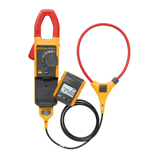
Product is a handheld, battery-operated Clamp Meter that has a remote-display module and detachable Flexible Current Probe (iFlex). Contact Fluke To contact Fluke, call one of the following telephone numbers: Technical Support USA: 1-800-44-FLUKE (1-800-443-5853) Calibration/Repair USA: 1-888-99-FLUKE (1-888-993-5853) Canada: 1-800-36-FLUKE (1-800-363-5853) -
Page 10: Safety Information
Calibration Manual Safety Information A Warning identifies conditions and actions that pose hazard(s) to the user. A Caution identifies conditions and procedures that could cause Meter damage, equipment under test damage, or permanent loss of data. Symbols used on the Product and in this manual are explained in Table 1. XWWarning To prevent possible electrical shock, fire, or personal injury: Use the Product only as specified, or the protection... - Page 11 If damaged, the Product may not be safe for use. Return the Product to Fluke for replacement of the seal. Do not exceed the Measurement Category (CAT) rating of the lowest rated individual component of a product, probe, or accessory.
-
Page 12: Symbols
Do not apply to or remove from HAZARDOUS LIVE conductors is HAZARDOUS LIVE conductors. permitted. Do not dispose of this product as unsorted municipal waste. Go to Fluke’s website for recycling information. Note The Measurement Category (CAT) and voltage rating of any combination of test probe, test probe accessory, current clamp accessory, and the Meter is the LOWEST rating of any individual component. -
Page 13: The Meter
Remote Display True-rms Clamp Meter The Meter The Meter Tactile Barrier ghn02.eps Figure 1. The Meter Specifications Electrical Specifications AC Current Via Jaw Range ............. 999.9 A Resolution ..........0.1 A Accuracy ..........2 % 5 digits (10-100 Hz) 5 digits (100-500 Hz) Crest Factor (50/60 Hz) ...... - Page 14 Calibration Manual Position Sensitivity Figure 2 shows the position sensitivity of the iFlex. ghn12.eps Distance from i2500-10 Flex i2500-18 Flex Error Optimum 0.5 in (12.7 mm) 1.4 in (35.6 mm) 0.5 % 0.8 in (20.3 mm) 2.0 in (50.8 mm) 1.0 % 1.4 in (35.6 mm) 2.5 in (63.5 mm)
-
Page 15: Mechanical Specifications
Remote Display True-rms Clamp Meter Specifications Trigger Level ........... 5 to 10 Hz, 10 A 10 to 100 Hz, 5 A 100 to 500 Hz, 10 A Frequency via iFlex Range ............ 5.0 to 500.0 Hz Resolution ..........0.1 Hz Accuracy .......... -
Page 16: Required Equipment
The equipment listed in Table 2 is required for performance tests and calibration adjustment. Table 2. Required Equipment Equipment Required Characteristics Recommended Model Calibrator 4.5-digit resolution Fluke 552xA Calibrator Wired coil 50 turns 5500A/COIL Test Probe for iFlex 2 mm to 4 mm Slim reach probe TP2, PN650892 Test Lead... - Page 17 Remote Display True-rms Clamp Meter Performance Tests 50-Turn Current Coil Conductor 5522A Polarity is Reversed • ghn07.eps Figure 4. Performance Test Connections for AC Amps, DC Amps, and Frequency...
- Page 18 Calibration Manual 5522A • ghn15.eps Figure 5. Performance Test Connections for AC Voltage, DC Voltage, and Frequency...
-
Page 19: Performance Tests
Remote Display True-rms Clamp Meter Performance Tests Table 3. Performance Tests Test UUT Meter Reading Limits Calibrator Output Nominal (Switch Value High Position) 20 V 20 V, 20 Hz 19.2 20.8 10 V 10 V, 50 Hz 10.7 600 V 600 V, 50Hz 590.5 609.5... - Page 20 Calibration Manual Table 3. Performance Tests (cont.) Test UUT Meter Reading Limits Calibrator Output Nominal (Switch Value High Position) 10 A 0.2 A, 50 Hz 10.7 100 A 2 A, 50 Hz 97.5 102.5 600 A 12 A, 50 Hz 587.5 612.5 AC Amps...
- Page 21 Remote Display True-rms Clamp Meter Performance Tests Performance tests for the iFlex are in Table 4. Connect the 5520A A ac output to the 50- turn coil. Figures 6 and 7 show the performance test connections for the iFlex. For the iFlex simulated tests you need the leads and probes listed in the required equipment list.
-
Page 22: Iflex Performance Tests
Calibration Manual 5522A • ghn14.eps Figure 7. Current Test Simulated with Voltage Table 4. iFlex Performance Tests Test UUT Meter Reading Limits Calibrator Output Nominal (Switch Value High Position) 10 A 0.2 A, 50 Hz 10.8 600 A 12 A, 50 Hz 581.5 618.5 995 A... -
Page 23: Calibration Adjustment
Remote Display True-rms Clamp Meter Calibration Adjustment Calibration Adjustment Calibration Password Operation Procedure A password is required to access the Calibration adjustment section of the Product. This section explains how this functionality works. To enter a password: 1. Push and turn the rotary switch to . The display shows “CAL”. 2. -
Page 24: Change The Password
Calibration Manual Change the Password To change the password: 1. The display shows “----“. 2. Enter the 4-digit password. For this step, the keys are mapped to the corresponding digits: - - - - After all 4 digits are entered, the leading “-“ icon appears on the display. 3. -
Page 25: Balance Adjustment
Remote Display True-rms Clamp Meter Calibration Adjustment 6. Turn the Rotary Switch to the function you wish to calibrate. If you wish to adjust Jaw balance, see Balance Adjustment. 7. Push . 8. See Table 5 and apply the required inputs. 9. -
Page 26: Adjustment Procedure
Calibration Manual Table 5. Adjustment Procedure Test Product Action (Switch Reading Position) C-01 0 V dc C-02 1000 V dc DC Volts C-03 600 V, 60 Hz C-04 600 V, 150 Hz C-05 600 V, 250 Hz AC Volts C-06 600 V, 350 Hz C-07 600 V, 440 Hz... -
Page 27: Maintenance
Remote Display True-rms Clamp Meter Maintenance Maintenance Clean the Product WCaution To prevent possible damage to the Product or to equipment under test, do not use abrasive cleaners. They will damage the case. To clean the Product, use a cloth with a mild cleaning solution. Battery Replacement XW Warning To prevent possible explosion, fire, or personal injury, Replace... -
Page 28: User Replaceable Parts
Battery Door - Display Module 3766406 Battery Door - Main Base 3766445 Remote Display 3752973 Soft Case 3538357 Users Manual 3782019 TL175 test leads 3798105 Fluke I2500-18 Rogowski coil 1670641 Alligator,2 mm jack, red boot 1670652 Alligator,2 mm jack, black boot...
Need help?
Do you have a question about the 381 and is the answer not in the manual?
Questions and answers