Fluke 302+, 303, 305 - Clamp Meter Manual
- User manual (25 pages) ,
- Calibration manual (20 pages)
Advertisement
Introduction
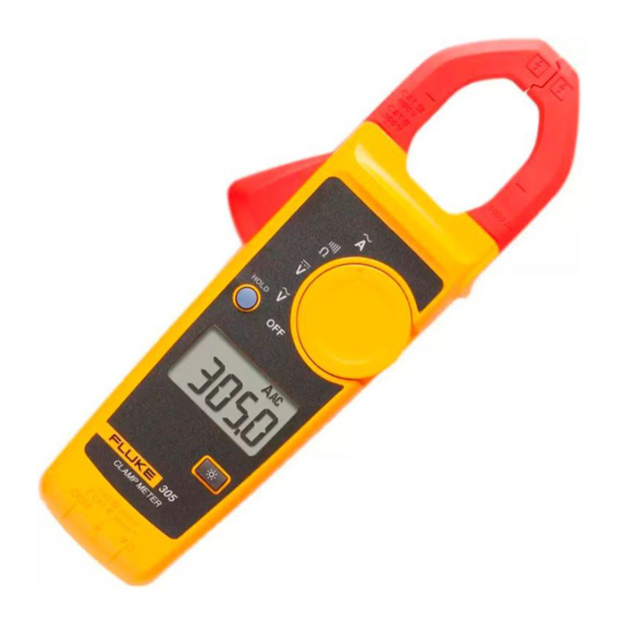
The Fluke 302+, 303, and 305 Clamp Meters (the Product) measures ac and dc voltage, ac current, resistance, and continuity.

Read "Safety Information" before you use the Product.
Specifications
Electrical Specifications
AC Current (Jaw)
| Range | |
| 302+ | 400.0 A |
| 303 | 600.0 A |
| 305 | 999.9 A |
| Resolution | 0.1 A |
| Accuracy | |
| 302+/303 | 1.8% ±5 digits (45 Hz to 65 Hz) 2.5% ±5 digits (65 Hz to 400 Hz) |
| 305 | 1.5% ±5 digits (45 Hz to 400 Hz) Note: Add 2% for position sensitivity. |
AC Voltage
| Range | 600.0 V |
| Resolution | 0.1 V |
| Accuracy | 1.5% ± 5 digits (45 Hz to 400 Hz) |
DC Voltage
| Range | 600.0 V |
| Resolution | 0.1 V |
| Accuracy | 1% ± 5 digits |
Resistance
| Range | 400.0 Ω/4000 Ω |
| Resolution | 0.1 Ω/1 Ω |
| Accuracy | 1% ±5 digits |
| Continuity Beeper | ≤70 Ω |
Mechanical Specifications
302+/303
| Size (L x W x H) | (207 x 75 x 34) mm |
| Weight | 265 g |
305
| Size (L x W x H) | (207 x 75 x 34) mm |
| Weight | 205 g |
Environmental Specifications
| Operating Temperature | 0°C to +40°C |
| Storage Temp | -30°C to +60°C |
| Operating Humidity | Non condensing (<10°C) ≤90% RH (at 10°C to 30°C) ≤75% RH (at 30°C to 40°C) (Without Condensation) |
| Operating Altitude | 2000 meters |
| Storage Altitude | 12,000 meters |
| EMI, EMC | Meets all applicable requirements in EN/IEC 61326-1 |
| Temperature Coefficients | Add 0.1 x specified accuracy for each °C above 28°C or below 18°C |
| Measurement Category | CAT IV 300 V, CAT III 600 V |
| Safety Compliance | EN/IEC 61010-1, Pollution Degree 2 EN/IEC 61010-2-032 EN/IEC 61010-031/A1  |
| IP Rating | IP 30 Per IEC 60529; Non-operating |
| Batteries | 2 AAA, NEDA 24A, IEC LR03 |
Maintenance
Clean the Product

To prevent possible damage to the Product or to equipment under test, do not use abrasive cleaners. They will damage the case.
To clean the Product, use a cloth with a mild cleaning solution.
Battery Replacement
To prevent possible explosion, fire, or personal injury, replace the batteries when the low battery indicator ( ) shows to prevent incorrect measurements.
To prevent possible damage to the Product or to equipment under test:
- Remove batteries to prevent battery leakage and damage to the Product if it is not used for an extended period.
- Be sure that the battery polarity is correct to prevent battery leakage.
To change the batteries, see Figure 2:

- Make sure the Product is off.
- Turn over the Product to access the battery compartment door screw.
- Use a flat-head screwdriver to loosen the battery compartment door screw and lift off the battery compartment door.
- Replace the two AAA batteries. Make sure to use the correct polarity when you put the batteries into the battery compartment door.
- Reattach the battery compartment door.
- Tighten the battery compartment door screw.
Jaw Maintenance
If the Product does not work properly:
- Inspect the jaw mating surface for cleanliness. If any foreign material (including rust) is present, the jaw will not close properly and measurement errors will result.
- Open the jaws and wipe the clamp metal ends with a non-flammable oil and cloth.
User-Replaceable Parts
User-replaceable parts are shown in Table 2. To order parts, see "Contact Fluke".
Table 2. User-Replaceable Parts
| Fluke Part Number | Description | Quantity |
| 3986568 | FLUKE-CAP-2001,TL7X PROBE CAP,BLACK | 1 |
| 3986579 | FLUKE-CAP-2001-01,TL7X PROBE CAP,FLUKE RED | 1 |
| 2444986 | BATTERY 1.5V MICRO ALKALINE IEC LR03 AAA | 2 |
| 4087581 | BATTERY DOOR (China only) | 1 |
| 4198591 | BATTERY DOOR (Brazil only) | 1 |
| 3765741 | FOAM BAG | 1 |
| 4045130 | 302+/303 USERS MANUAL | 1 |
| 4045148 | 305 USERS MANUAL | 1 |
Required Equipment
The equipment in Table 3 is necessary for the performance tests and calibration adjustment.
Table 3. Required Equipment
| Equipment | Required Characteristics | Recommended Model |
| Calibrator | 4.5-digit resolution | FLUKE 5522A or equivalent |
| Wired coil | 50 turns | FLUKE 5500A/Coil or equivalent |
Performance Tests

To prevent possible electrical shock, fire, or personal injury, do not go through the performance test procedures unless the Product is fully assembled.
The performance tests verify the full operation of the Product and measure the accuracy of each function against the Product specifications. If the Product fails a part of the test, calibration adjustment and/or repair is necessary. See "Calibration Adjustment".
Before you do the performance tests:
- Make sure that you have the necessary equipment. See Table 3.
- Make sure the Product batteries are good and replace them if necessary. See "Battery Replacement".
- Warm up the Calibrator as necessary. Refer to its specifications.
- Let the temperature of the UUT (unit under test) become stable to room temperature.
Test the Display and Firmware Version
To verify that all segments of the display function:
- With the Product off, push and hold
![]() .
. - Turn the Product on.
- All display segments are shown. See Figure 3.


If segments of the display are missing, repair is necessary. See "Contact Fluke".
When  is released, the firmware current version is shown:
- "r007" is shown for 302+/303.
- "r004" is shown for 305.
"F30x" designates model number 302+, 303 or 305.
Backlight
To verify that the backlight functions:
- With the Product on, push
![]() . The backlight comes on.
. The backlight comes on. - Push
![]() again to turn off the backlight.
again to turn off the backlight. - If the backlight does not function correctly, repair is necessary. See "Contact Fluke".
Button Test
To verify that the buttons function, turn on the Product and push each button separately. Each button push causes the Product to beep. When you push the HOLD button,  shows on the display. If the buttons do nothing, repair is necessary. See "Contact Fluke".
Current
To do the ac current test:
- Connect the Calibrator A ac output and ground to the 50-Turn Coil. See Figure 4 for test connections.
- Turn the Product to
![]() .
. - Apply the input level for each step shown in Table 4.
- Compare the indication on the Product display with the UUT reading limits in Table 4.
- If the display indication is outside of the range shown in Table 4, calibration adjustment or repair of the Product is necessary. See "Calibration Adjustment".
 .
.Table 4. AC Current Performance Tests


Figure 4. AC Current Test Connections
Volts and Ohms
To do the Volts and Ohms performance tests, turn the rotary switch to the necessary function and apply the values shown in Table 5. See Figure 5 for the test connections.
Table 5. Volts and Ohms Performance Tests
| Test (Switch Position) | Calibrator Output | UUT Meter Reading Limit | |
| Low | High | ||
 V ac | 10 V @ 50 Hz | 9.4 V | 10.7 V |
| 600 V @ 50 Hz | 590.5 V | 609.5 V | |
| 600 V @ 400 Hz | 590.5 V | 609.5 V | |
| V dc | -600 V | -606.5 V | -593.5 V |
| -10 V | -10.6 V | -9.4 V | |
| 10 V | 9.4 V | 10.6 V | |
| 600 V | 593.5 V | 606.5 V | |
 Ohms | 0 Ω | 0.0 Ω | 0.5 Ω |
| 10 Ω | 9.4 Ω | 10.6 Ω | |
| 350 Ω | 346.0 Ω | 354.0 Ω | |
| 3500 Ω | 3460 Ω | 3540 Ω | |

Figure 5. Volts and Ohms Performance Test Connections
Calibration Adjustment
The Product features closed-case calibration adjustment and uses known reference sources. The Product measures the applied reference source, calculates correction factors, and stores the correction factors in nonvolatile memory.
Should the Product fail any of the performance tests, do the calibration adjustment procedure.
To do the calibration adjustment:
- Remove the Product battery door. See "Battery Replacement".
- Apply 3.0 V across the battery contacts on the pca. Note the polarity that is shown in Figure 6.
- Turn the rotary switch to the function to be adjusted.
- Remove the calibration seal.
- Short across the CAL keypad on the pca and then remove the short. See Figure 6. This puts the Product into calibration mode.
- When "C-1.2" is shown on the display, apply the correct input signals shown in Table 6 to the Product. For each function, the calibration step shown on the display will advance.
- After each step, push the HOLD button to confirm the calibration step, store the value, and go to the next step.
Set the Calibrator to Standby after you complete adjustment of each function.
Notes
If any calibration point is missing, "Err" is shown on the display. After you push the HOLD button, wait until the calibration step number advances before you change the calibrator source. Some adjustment steps can take several seconds to execute before the Product goes to the subsequent step.- When calibration adjustment is complete, remove the 3.0 V supply. The Product will exit the calibration mode automatically.
- Replace the batteries and battery door.

Figure 6. Short the CAL Keypad
Table 6. Calibration Adjustment

Safety Information
identifies conditions and procedures that are dangerous to the user.
identifies conditions and procedures that could cause Product damage, equipment under test damage, or permanent loss of data.
Table 1 shows the symbols used on the Product and in this manual.
To prevent possible electrical shock, fire, or personal injury:

- Use the Product only as specified, or the protection supplied by the Product can be compromised.
- Read all safety Information before you use the Product.
- Carefully read all instructions.
- Use only correct measurement category (CAT), voltage, and amperage rated probes, test leads, and adapters for the measurement.
- Do not touch voltages > 30 V ac rms, 42 V ac peak, or 60 V dc.
- Hold the Product behind the tactile barrier. See The Clamp Meter. See Figure 1, item
![]() .
. - Do not exceed the Measurement Category (CAT) rating of the lowest rated individual component of a Product, probe, or accessory.
- Do not measure current while the test leads are in the input jacks.
- Do not use the Product around explosive gas, vapor, or in damp or wet environments.
- Limit operation to the specified measurement category, voltage, or amperage ratings.
- Do not work alone.
- Do not apply more than the rated voltage, between the terminals or between each terminal and earth ground.
- Comply with local and national safety codes. Use personal protective equipment (approved rubber gloves, face protection, and flame-resistant clothes) to prevent shock and arc blast injury where hazardous live conductors are exposed.
- Replace the batteries when the low battery indicator shows to prevent incorrect measurements.
- The battery door must be closed and locked before you operate the Product.
- Measure a known voltage first to make sure that the Product operates correctly.
- Remove all probes, test leads, and accessories that are not necessary for the measurement.
- Only use probes, test leads, and accessories that have the same measurement category and voltage rating as the Product.
- Keep fingers behind the finger guards on the probes.
- Connect the common test lead before the live test lead and remove the live test lead before the common test lead.
- Remove all probes, test leads, and accessories before the battery door is opened.
- Do not use and disable the Product if it is damaged.
- Do not use the Product if it operates incorrectly.
- Do not use test leads if they are damaged. Examine the test leads for damaged insulation, exposed metal. Check test lead continuity.
- Before each use, examine the Product. Look for cracks or missing pieces of the clamp housing. Also look for loose or weakened components. Carefully examine the insulation around the jaws. See Figure 1, item
![]() .
. - Examine the case before you use the Product. Look for cracks or missing plastic. Carefully look at the insulation around the terminals.
- Remove batteries to prevent battery leakage and damage to the Product if it is not used for an extended period.
- Remove the batteries if the Product is not used for an extended period of time, or if stored in temperatures above 50 °C. If the batteries are not removed, battery leakage can damage the Product.
- Do not use the Product with pulse width modulated motor controllers.
- Do not use a current measurement as an indication that a circuit is safe to touch. A voltage measurement is necessary to know if a circuit is hazardous.
 .
. .
.Table 1. Symbols
| Symbol | Meaning | Symbol | Meaning |
 | AC (Alternating Current) |  | Earth ground |
 | DC (Direct Current) |  | This product complies with the WEEE Directive (2002/96/EC) marking requirements. The affixed label indicates that you must not discard this electrical/electronic product in domestic household waste. Product Category: With reference to the equipment types in the WEEE Directive Annex I, this product is classed as category 9 "Monitoring and Control Instrumentation" product. Do not dispose of this product as unsorted municipal waste. Go to Fluke's website for recycling information. Note This product complies with the Regulation for the Administration of the Recovery and Disposal of Waste Electrical and Electronic Products (China). |
 | Hazardous voltage. Risk of electric shock. |  | Conforms to European Union directives. |
 | Risk of Danger. Important information. See Manual. |  | Double insulated |
 | Battery | | Application to or removal from hazardous, live conductors is permitted. |
| CAT II | Measurement category II is applicable to test and measuring circuits connected directly to utilization points of low voltage mains installation. | CAT III | Measurement Category III is applicable to test and measuring circuits connected to the distribution part of the building's low-voltage MAINS installation. |
| CAT IV | Measurement Category IV is applicable to test and measuring circuits connected at the source of the building's low-voltage MAINS installation. |  | This product has been tested to the requirements of CAN/CSA-C22.2 No. 61010-1, second edition, including Amendment 1, or a later version of the same standard incorporating the same level of testing requirements. |
Note
The Measurement Category (CAT) and voltage rating of combinations of test probes, test probe accessories, current clamp accessories, and the Product is the LOWEST rating of individual components.
Contact Fluke
1.800.561.8187
www.itm.com
information@itm.com
Documents / Resources
References
Download manual
Here you can download full pdf version of manual, it may contain additional safety instructions, warranty information, FCC rules, etc.
Advertisement


Need help?
Do you have a question about the 302+ and is the answer not in the manual?
Questions and answers