Fluke 374 FC, 375 FC, 376 FC Manual
- User manual (35 pages) ,
- Calibration manual (20 pages) ,
- User manual (32 pages)
Advertisement
- 1 Introduction
- 2 Safety Information
- 3 Replacement Part List
-
4
The Product
- 4.1 Device Overview
- 4.2 Auto Power Off
- 4.3 Backlight
- 4.4 Display Hold
- 4.5 MIN MAX AVG
- 4.6 LOG
- 4.7 Clear Memory
- 4.8 AC Flexible Current Probe
- 4.9 AC Current Jaw
- 4.10 Frequency Measurement
- 4.11 DC Current Measurement
- 4.12 AC and DC Voltage Measurement
- 4.13 Continuity/Resistance Measurement
- 4.14 Capacity Measurement
- 4.15 Inrush Current Measurement
- 4.16 Battery Replacement
- 4.17 Fluke Connect Bluetooth Connection to FC Tools
- 5 Specifications
- 6 LIMITED WARRANTY AND LIMITATION OF LIABILITY
- 7 Contact Fluke
- 8 Documents / Resources
Introduction
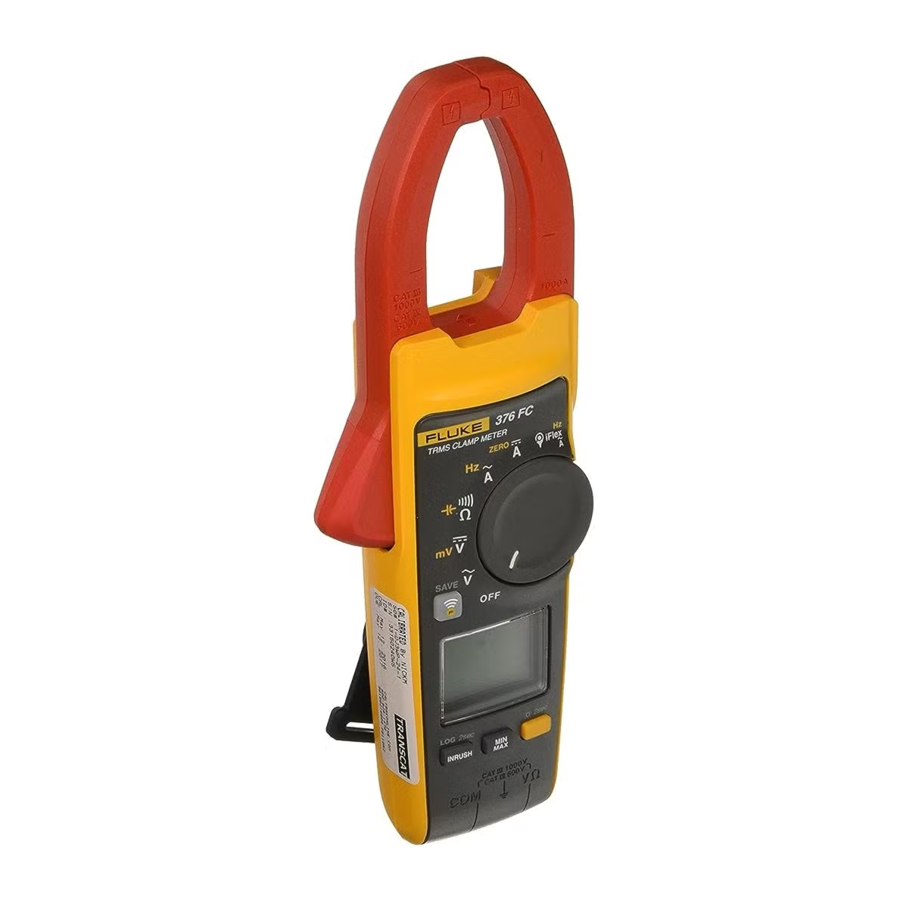
The Fluke 374 FC/375 FC/376 FC (the Product) measures true-rms ac current and voltage, dc current and voltage, inrush current, resistance, and capacitance. The 375 FC and 376 FC also measure frequency and dc millivolts. The detachable iFlex (Flexible Current Probe) that is included with the 376 FC (optional with the 374 FC and 375 FC) expands the measurement range to 2500 A ac. The Flexible Current Probe provides increased display flexibility and allows measurements of awkward sized conductors and improved wire access. The illustrations in this manual show the 376 FC.
Safety Information

A Warning identifies conditions and procedures that are dangerous to the user.

A Caution identifies conditions and procedures that can cause damage to the Product or the equipment under test.
Symbols used on the Product and in this manual are explained in Table 1.
Table 1. Symbols
| Symbol | Meaning | Symbol | Meaning |
 | AC (Alternating Current) |  | Earth |
 | DC (Direct Current) |  | WARNING. HAZARDOUS VOLTAGE. Risk of electric shock. |
 | Double Insulated |  | WARNING. RISK OF DANGER. |
 | Do not apply to or remove from HAZARDOUS LIVE conductors. Do not apply around or remove from uninsulated hazardous live conductors without taking additional protective measures |  | Battery. Low battery when shown on display. |
 | Application around and removal from uninsulated hazardous live conductors is permitted. |  | Measurement Category IV is applicable to test and measuring circuits connected at the source of the building's low-voltage MAINS installation. |
 | Measurement Category III is applicable to test and measuring circuits connected to the distribution part of the building's low-voltage MAINS installation. | ||


To prevent possible electrical shock, fire, or personal injury:
- Carefully read all instructions.
- Read all safety information before you use the Product.
- Use the Product only as specified, or the protection supplied by the Product can be compromised.
- Do not use the Product around explosive gas, vapor, or in damp or wet environments.
- Do not use and disable the Product if it is damaged.
- Do not use the Product if it operates incorrectly.
- Use only correct measurement category (CAT), voltage, and amperage rated probes, test leads, and adapters for the measurement.
- Do not exceed the Measurement Category (CAT) rating of the lowest rated individual component of a Product, probe, or accessory.
![shock hazard]() Comply with local and national safety codes. Use personal protective equipment (approved rubber gloves, face protection, and flame-resistant clothes) to prevent shock and arc blast injury where hazardous live conductors are exposed.
Comply with local and national safety codes. Use personal protective equipment (approved rubber gloves, face protection, and flame-resistant clothes) to prevent shock and arc blast injury where hazardous live conductors are exposed.- Before each use, examine the Product. Look for cracks or missing pieces of the clamp housing or output cable insulation. Also look for loose or weakened components. Carefully examine the insulation around the jaws.
- Do not use test leads if they are damaged. Examine the test leads for damaged insulation and measure a known voltage.
- Do not touch voltages >30 V ac rms, 42 V ac peak, or 60 V dc.
- Do not measure current while the test leads are in the input jacks.
- Do not apply more than the rated voltage, between the terminals or between each terminal and earth ground.
- De-energize the circuit or wear personal protective equipment in compliance with local requirements before you apply or remove the Flexible Current Probe.
- Measure a known voltage first to make sure that the Product operates correctly.
- Limit operation to the specified measurement category, voltage, or amperage ratings.
- The battery door must be closed and locked before you operate the Product.
- Connect the common test lead before the live test lead and remove the live test lead before the common test lead.
- Remove all probes, test leads, and accessories before the battery door is opened.
- Keep fingers behind the finger guards on the probes.
- Hold the Product behind the tactile barrier.
- Replace the batteries when the low battery indicator shows to prevent incorrect measurements.
- Do not use the HOLD function to measure unknown potentials. When HOLD is turned on, the display does not change when a different potential is measured.
- Disconnect power and discharge all high-voltage capacitors before you measure resistance, continuity, capacitance, or a diode junction.
- Remove the input signals before you clean the Product.
- Use only specified replacement parts.
- When batteries are changed, ensure that the calibration seal in the battery compartment is not damaged. If damaged, the Product may not be safe to use. Return the Product to Fluke for replacement of the seal.
- Do not use in CAT III or CAT IV environments without the protective cap of test probe, The protective cap decreases the expose probe metal < 4mm. This decreases the possibility of arc flash from short circuits.
- Do not place magnet inside Category IV panel. Place it outside the panel instead.
For safe operation and maintenance of the Product:
- Repair the Product before use if the battery leaks.
- Have an approved technician repair the Product.
To avoid possible damage to the Product or to equipment under test:
- Use the proper jacks, function, and range for the measurement application.
- Clean the case and accessories with a damp cloth and mild detergent only. Do not use abrasives or solvents.
Note
The Measurement Category (CAT) and voltage rating of any combination of test probe, test probe accessory, current clamp accessory, and the Product is the LOWEST rating of any individual component.
Replacement Part List
Table 2 lists the available replacement parts.
Table 2. Replacement Parts
| Item | Qty. | Fluke Part or Model Number |
| Battery, AA 1.5 V | 2 | 376756 |
| Battery Door Assembly | 1 | 4696918 |
| Test lead set | 1 | TL75 |
| Flexible current probe i2500-10 | 1 | 3676410 |
| Flexible current probe i2500-18 | 1 | 3798105 |
| Magnet strap | 1 | 669952 |
| STRAP 9 INCHES | 1 | 669960 |
| Soft Case | 1 | 3752958 |
The Product
Device Overview

Auto Power Off

Backlight

Display Hold

MIN MAX AVG

LOG
(375 FC and 376 FC)

Clear Memory
(375 FC and 376 FC)

AC Flexible Current Probe

AC Current Jaw

Frequency Measurement
Hz (375 FC & 376 FC)

DC Current Measurement

AC and DC Voltage Measurement

Continuity/Resistance Measurement

Capacity Measurement

Inrush Current Measurement

Battery Replacement

Fluke Connect Bluetooth Connection to FC Tools

Go to www.flukeconnect.com


Specifications
| Maximum voltage between any Terminal and Earth Ground | 1000 V | |
| Batteries | 2 AA, NEDA 15A, IEC LR6 | |
| Operating Temperature | -10°C to +50°C | |
| Storage Temperature | -40°C to +60°C | |
| Operating Humidity | Non condensing (<10°C) ≤90% RH (at 10°C to 30°C) ≤75% RH (at 30°C to 40°C) ≤45% RH (at 40°C to 50°C) | |
| Operating Altitude | 2000 m | |
| Storage Altitude | 12,000 m | |
| Size (L x W x H) | 249 mm x 85 mm x 45 mm | |
| Weight | 410 g | |
| Jaw Opening | 34 mm | |
| Flexible Current Probe Diameter | 7.5 mm | |
| Flexible Current Probe Cable Length (head to electronics connector) | 1.8 m | |
| Safety | IEC 61010-1, Pollution Degree 2 IEC 61010-2-032: CAT III 1000V / CAT IV 600V IEC 61010-2-033: CAT III 1000V / CAT IV 600V | |
| Intrusion Protection (IP) Rating | IEC 60529: IP30 | |
| Radio Frequency Certification | FCC ID:T68-FBLE IC:6627A-FBLE | |
| Wireless Radio Frequency Range | 2412 MHz to 2462 MHz | |
| Output Power | <100 mW | |
| Electromagnetic Compatibility (EMC) International | IEC 61326-1: Portable, Electromagnetic Environment, IEC 61326-2-2, CISPR 11: Group 1, Class A | |
| Group 1: Equipment has intentionally generated and/or uses conductively-coupled radio frequency energy that is necessary for the internal function of the equipment itself. Class A: Equipment is suitable for use in all establishments other than domestic and those directly connected to a low-voltage power supply network that supplies buildings used for domestic purposes. There may be potential difficulties in ensuring electromagnetic compatibility in other environments due to conducted and radiated disturbances. Emissions that exceed the levels required by CISPR 11 can occur when the equipment is connected to a test object. | ||
| Temperature Coefficients | Add 0.1 x specified accuracy for each degree C above 28°C or below 18°C | |
| AC Current via Jaw | ||
| Range | 374 FC and 375 FC | 600.0 A |
| 376 FC | 999.9 A | |
| Resolution | 0.1 A | |
| Accuracy | 2% ±5 digits (10 Hz to 100 Hz) 2.5% ±5 digits (100 to 500 Hz) | |
| Crest Factor (50 Hz/60 Hz) | 376 FC | 3 @ 500 A 2.5 @ 600 A 1.42 @ 1000 A |
| 374 FC and 375 FC | 2.5 @ 350 A 1.42 @ 600 A | |
| Note: Add 2% for C.F. >2 | ||
| AC Current via Flexible Current Probe | ||
| Range | 2500 A | |
| Resolution | 0.1 A (≤999.9 A) 1 A (≤2500 A) | |
| Accuracy | 3% ±5 digits (5 to 500 Hz) | |
| Crest Factor (50 Hz/60 Hz) | 3.0 @ 1100 A 2.5 @ 1400 A 1.42 @ 2500 A Add 2% for C.F. >2 | |

Position Sensitivity (see Figure 1)
| Distance from Optimum | i2500-10 Flex | i2500-18 Flex | Error |
| A | 0.5 in (12.7 mm) | 1.4 in (35.6 mm) | ±0.5% |
| B | 0.8 in (20.3 mm) | 2.0 in (50.8 mm) | ±1.0% |
| C | 1.4 in (35.6 mm) | 2.5 in (63.5 mm) | ±2.0% |
Measurement uncertainty assumes centralized primary conductor at optimum position, no external electrical or magnetic field, and within operating temperature range.
| DC Current | ||
| Range | 374 FC and 375 FC | 600.0 A |
| 376 FC | 999.9 A | |
| Resolution | 0.1 A | |
| Accuracy | 2% ±5 digits | |
| AC Voltage | ||
| Range | 1000 V | |
| Resolution | 0.1 V (≤600.0 V) 1 V (≤1000 V) | |
| Accuracy | 1.5% ±5 digits (20 Hz to 500 Hz) | |
| DC Voltage | ||
| Range | 1000 V | |
| Resolution | 0.1 V (≤600.0 V) 1 V (≤1000 V) | |
| Accuracy | 1% ±5 digits | |
| mV dc (375 FC and 376 FC) | ||
| Range | 500.0 mV | |
| Resolution | 0.1 mV | |
| Accuracy | 1% ±5 digits | |
| Frequency via Jaw | ||
| Range 375 FC and 376 FC | 5.0 Hz to 500.0 Hz | |
| Resolution | 0.1 Hz | |
| Accuracy | 0.5% ±5 digits | |
| Trigger Level | 5 Hz to 10 Hz, ≥10 A 10 Hz to 100 Hz, ≥5 A 100 Hz to 500 Hz, ≥10 A | |
| Frequency via Flexible Current Probe | ||
| Range 375 FC and 376 FC | 5.0 Hz to 500.0 Hz | |
| Resolution | 0.1 Hz | |
| Accuracy | 0.5% ±5 digits | |
| Trigger Level | 5 Hz to 20 Hz, ≥25 A 20 Hz to 100 Hz, ≥20 A 100 Hz to 500 Hz, ≥25 A | |
| Resistance | ||
| Range | 374 FC | 6000 Ω |
| 375 FC and 376 FC | 60 kΩ | |
| Resolution | 374 FC | 0.1 Ω (≤600 Ω) 1 Ω (≤6000 Ω) |
| 375 FC and 376 FC | 0.1 Ω (≤600 Ω) 1 Ω (≤6000 Ω) 10 Ω (≤60 kΩ) | |
| Accuracy | 1% ±5 digits | |
| Capacitance | ||
| Range | 1000 μF | |
| Resolution | 0.1 μF (≤100 μF) 1 μF (≤1000 μF) | |
| Accuracy | 1% ±4 digits | |
LIMITED WARRANTY AND LIMITATION OF LIABILITY
To obtain service during the warranty period, contact your nearest Fluke authorized service center to obtain return authorization information, then send the product to that Service Center with a description of the problem.
Fluke Corporation
P.O. Box 9090
Everett, WA 98206-9090
U.S.A.
Fluke Europe B.V.
P.O. Box 1186
5602 BD Eindhoven
The Netherlands
Contact Fluke
To contact Fluke, call one of the following telephone numbers:
- Technical Support USA: 1-800-44-FLUKE (1-800-443-5853)
- Calibration/Repair USA: 1-888-99-FLUKE (1-888-993-5853)
- Canada: 1-800-36-FLUKE (1-800-363-5853)
- Europe: +31 402-675-200
- Japan: +81-3-6714-3114
- Singapore: +65-6799-5566
- Anywhere in the world: +1-425-446-5500
Or, visit Fluke's website at www.fluke.com.
To register your product, visit http://register.fluke.com.
Documents / Resources
References
![www.flukeconnect.com]() Fluke Connect
Fluke Connect![www.fluke.com]() Fluke Corporation: Fluke Electronics, Calibration and Networks
Fluke Corporation: Fluke Electronics, Calibration and NetworksFluke Registration
![www.apple.com]() App Store - Apple
App Store - Apple![play.google.com]() Google Play
Google Play
Download manual
Here you can download full pdf version of manual, it may contain additional safety instructions, warranty information, FCC rules, etc.
Advertisement


Need help?
Do you have a question about the 374 FC and is the answer not in the manual?
Questions and answers