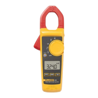
Fluke 324 User Manual
Clamp meter
Hide thumbs
Also See for 324:
- Manual (72 pages) ,
- Calibration manual (43 pages) ,
- User manual (27 pages)
Table of Contents
Advertisement
Quick Links
Advertisement
Table of Contents

Related Manuals for Fluke 324


Summary of Contents for Fluke 324
- Page 1 User Manual of Product 1: Fluke 324 40/400A AC, 600V AC/DC True-RMS Clamp Meter with Temperature, and Capacitance Measurements User Manual of Product 2: Klein Tools ET310 AC Circuit Breaker Finder, Electric Tester With Integrated GFCI Outlet Tester...
- Page 2 323/324/325 Clamp Meter Users Manual May 2012 Rev.1, 06/15 © 2012-2015 Fluke Corporation. All rights reserved. Specifications are subject to change without notice. All product names are trademarks of their respective companies.
- Page 3 LIMITED WARRANTY AND LIMITATION OF LIABILITY This Fluke product will be free from defects in material and workmanship for two years from the date of purchase. This warranty does not cover fuses, disposable batteries, or damage from accident, neglect, misuse, alteration, contamination, or abnormal conditions of operation or handling.
-
Page 4: Table Of Contents
Table of Contents Title Page Introduction ......................... 1 How to Contact Fluke ....................1 Safety Information ...................... 2 How to Clean the Product ..................9 Specifications ......................10 Electrical Specifications ..................10 Mechanical Specifications ..................12 Environmental Specifications ................. 12... - Page 5 323/324/325 Users Manual...
-
Page 6: Introduction
Introduction The Fluke 323/324/325 Clamp Meter (the Product) measures ac and dc voltage, ac current, resistance, and continuity. The 324 and 325 can also measure capacitance and contact temperature. The 325 can also measure dc current and frequency. Note that the 325 is shown in all of the illustrations. -
Page 7: Safety Information
Japan: +81-03-6714-3114 • Singapore: +65-6799-5566 • Anywhere in the world: +1-425-446-5500 Or, visit Fluke's website at www.fluke.com. To register your product, visit http://register.fluke.com. To see, print, or download the latest manual supplement, visit http://us.fluke.com/usen/support/manuals. Safety Information A Warning identifies conditions and procedures that are dangerous to the user. A Caution identifies conditions and procedures that can cause damage to the Product or the equipment under test. - Page 8 Clamp Meter Safety Information Warning To prevent possible electrical shock, fire, or personal injury: • Use the Product only as specified, or the protection supplied by the Product can be compromised. • Use only correct measurement category (CAT), voltage, and amperage rated probes, test leads, and adapters for the measurement.
- Page 9 323/324/325 Users Manual • Do not apply more than the rated voltage, between the terminals or between each terminal and earth ground. • Comply with local and national safety codes. Use personal protective equipment (approved rubber gloves, face protection, and flame- resistant clothes) to prevent shock and arc blast injury where hazardous live conductors are exposed.
- Page 10 Clamp Meter Safety Information • Connect the common test lead before the live test lead and remove the live test lead before the common test lead. • Remove all probes, test leads, and accessories before the battery door is opened. •...
- Page 11 323/324/325 Users Manual • Remove batteries to prevent battery leakage and damage to the Product if it is not used for an extended period. • Remove batteries to prevent battery leakage and damage to the Product if is to be stored above its operating temperature.
- Page 12 Clamp Meter Symbols Symbols Table 1. Symbols Symbol Meaning Symbol Meaning AC (Alternating Current) Earth DC (Direct Current) AC and DC Current Conforms to European Union WARNING. RISK OF DANGER. directives. Consult user documentation. Battery WARNING.
- Page 13 323/324/325 Users Manual Table 1. Symbols (cont.) Symbol Meaning Symbol Meaning Measurement Category II is applicable to test and MEASUREMENT CATEGORY III is measuring circuits connected applicable to test and measuring directly to utilization points circuits connected to the distribution ...
-
Page 14: How To Clean The Product
Clamp Meter How to Clean the Product Note The Measurement Category (CAT) and voltage rating of combinations of test probes, test probe accessories, current clamp accessories, and the Product is the LOWEST rating of individual components. How to Clean the Product Regularly wipe the case with a damp cloth and weak detergent. -
Page 15: Specifications
Terminal and Earth Ground ....600 V Range 323 ............ 400.0 A 324, 325 ..........(40.00, 400.0) A Batteries ..........2 AAA, NEDA 24A, IEC LR03 Operating Temperature ......-10 °C to +50 °C Storage Temperature ......-30 °C to +60 °C Operating Humidity ......... - Page 16 Clamp Meter Specifications Weight 323 ............. 265 g 324 ............. 208 g 325 ............. 283 g Safety ............IEC 61010-1, Pollution Degree 2 IEC 61010-2-032: CATIV 300V / CATIII 600V IEC 61010-2-033:CAT IV 300V / CAT III 600V IP Rating ..........IEC 60529: IP30, non-operating...
-
Page 17: Mechanical Specifications
324, 325 ..........(0.01, 0.1) A Accuracy 323, 325 ..........2.0 % ±5 digits (45 – 65 Hz) 2.5 % ±5 digits (65 – 400 Hz) 324 ............ 1.5 % ±5 digits (45 Hz to 400 Hz) Note Add 2 % for position sensitivity. - Page 18 Range ............ 600.0 V Resolution ..........0.1 V Accuracy ..........1 % ± 5 digits Resistance Range 323, 324 ..........(400.0, 4000) Ω 325 ............. (400.0, 4000, 40000) Ω Resolution ..........(0.1, 1, 10) Ω Accuracy ..........1 % ±5 digits...
- Page 19 323/324/325 Users Manual Continuity Beeper 323 ............ ≤70 Ω 324/325 ..........≤30 Ω Capacitance (324, 325) Range............(100.0, 1000) μF Resolution ..........(0.1, 1) μF Accuracy ..........1 % ±4 digits Frequency with Jaw (325) Range............5.0 to 500.0 Hz Resolution ..........
-
Page 20: The Meter
Clamp Meter The Meter The Meter gtq008.eps... - Page 21 323/324/325 Users Manual MAXMIN 324/325 gtq001.eps...
- Page 22 Clamp Meter The Meter 2:00 2:00 gtq002.eps...
- Page 23 323/324/325 Users Manual 600 V 600 V 300 V 300 V 323, 324 TRUE RMS CLAMP METER TRUE RMS CLAMP METER 600 V 300 V 600 V 300 V gtq003.eps...
- Page 24 Clamp Meter The Meter 323 V dc - 323 V ac - 324, 325 V dc & V ac - >30 V 300 V gtq004.eps...
- Page 25 323/324/325 Users Manual 600 V 600 V 300 V 300 V TRUE RMS CLAMP METER TRUE RMS CLAMP METER 600 V 600 V 300 V 300 V <70 324/325 <30 gtq005.eps...
- Page 26 Clamp Meter The Meter HOLD TRUE RMS CLAMP METER 600 V 300 V > 30 V 20 V AC/DC & ZERO ZERO ZERO ZERO 2 sec AC/DC AC/DC AC/DC gtq006.eps...
- Page 27 323/324/325 Users Manual 324, 325 TRUE RMS CLAMP METER 600 V 300 V gtq009.eps...
- Page 28 Clamp Meter The Meter gtq007.eps...
- Page 29 323/324/325 Users Manual...
- Page 30 ET310 ENGLISH INSTRUCTION MANUAL Digital Circuit Breaker Finder Digital Circuit Breaker Finder Digital Circuit Breaker Finder • VISUAL & AUDIBLE INDICATIONS CLEARLY IDENTIFY CORRECT BREAKER • 90-120V AC OPERATION • DETERMINE WIRING CONDITION AT ELECTRICAL OUTLETS • TEST GFCI DEVICES IP40 ESPAÑOL pág.
- Page 31 ENGLISH GENERAL SPECIFICATIONS FEATURE DETAILS The Klein Tools ET310 is a digital circuit breaker finder used to locate the correct circuit breaker in a panel to which an electrical outlet or fixture is connected. The transmitter is connected to the electrical outlet or fixture in the circuit while the receiver is used to scan the breakers in the circuit breaker panel.
- Page 32 ENGLISH OPERATING INSTRUCTIONS WARNINGS POWER ON/OFF To ensure safe operation and service of the meter, follow these instructions. Failure to observe these warnings can result in Press the Power button to power on the receiver , press and hold the Power button to power off the receiver.
- Page 33 ENGLISH OPERATING INSTRUCTIONS OPERATING INSTRUCTIONS FINDING CIRCUIT BREAKERS CONNECTING TO OTHER FIXTURES USING OPTIONAL ACCESSORIES (CAT. NO. 69411) Insert the transmitter into the electrical outlet and note the Wiring Condition & . If the transmitter indicates that the outlet is LIGHT SOCKET FIXTURES energized and correctly wired, prepare to scan the breakers in the Screw the light fixture adapter into an empty light socket.
- Page 34 ENGLISH ET310 ESPAÑOL MAINTENANCE BATTERY REPLACEMENT MANUAL DE INSTRUCCIONES When the Power-On indicator blinks, the battery must be replaced. Detector digital 1. Open the battery compartment door by unscrewing the by unscrewing the locking screw. de cortacircuitos 2. Remove exhausted 9V battery and dispose of appropriately. Remove exhausted 9V battery and dispose of appropriately.
- Page 35 ESPAÑOL ESPECIFICACIONES GENERALES DETALLES DE LAS CARACTERÍSTICAS El ET310 de Klein Tools es un detector digital de cortacircuitos que se usa para ubicar el cortacircuitos correcto en un panel al que se conecta un tomacorrientes o accesorio eléctrico. El transmisor se conecta al tomacorrientes o al accesorio eléctrico en el circuito, mientras que el receptor se usa para escanear los cortacircuitos en el panel del cortacircuitos.
- Page 36 ESPAÑOL INSTRUCCIONES DE FUNCIONAMIENTO ADVERTENCIAS Inserte el transmisor en el tomacorrientes que se está probando y Para garantizar un funcionamiento y servicio seguros del compare los indicadores condiciones de cableado encendidos probador, siga estas instrucciones. El incumplimiento de estas los códigos de condiciones de cableado impresos en el transmisor advertencias puede provocar lesiones graves o la muerte.
- Page 37 ESPAÑOL INSTRUCCIONES DE FUNCIONAMIENTO INSTRUCCIONES DE FUNCIONAMIENTO CONECTAR A OTROS ACCESORIOS USANDO ACCESORIOS ENCONTRAR CORTACIRCUITOS OPCIONALES (CAT. N.º 69411) Inserte el transmisor en el tomacorrientes y revise las condiciones ACCESORIOS DE ILUMINACIÓN de cableado . Si el transmisor indica que el tomacorrientes Enrosque el adaptador de accesorios de iluminación a un enchufe está...
- Page 38 ESPAÑOL ET310 FRANÇAIS MANTENIMIENTO REEMPLAZO DE LA BATERÍA MANUEL D’UTILISATION Cuando el indicador de encendido parpadea, se debe reemplazar la batería. Localisateur de 1. Abra la tapa del compartimento de las baterías 10 10 disjoncteur numérique disjoncteur numérique disjoncteur numérique desenroscando el tornillo de bloqueo.
- Page 39 FRANÇAIS CARACTÉRISTIQUES GÉNÉRALES CARACTÉRISTIQUES DÉTAILLÉES Le localisateur de disjoncteur numérique ET310 de Klein Tools est utilisé pour localiser le disjoncteur auquel une prise électrique ou un appareil est raccordé dans un panneau de disjoncteurs. L’émetteur est connecté à la prise ou à l’appareil électrique dans le circuit tandis que le récepteur est utilisé...
- Page 40 FRANÇAIS INSTRUCTIONS D’UTILISATION AVERTISSEMENTS Pour garantir une utilisation et un entretien sécuritaires de Insérez l’émetteur dans la prise électrique à tester et comparez les voyants d’état lumineux du câblage avec les codes d’état du l’appareil, suivez ces instructions. Le non-respect de ces câblage imprimés sur l’émetteur (Fig.
- Page 41 FRANÇAIS INSTRUCTIONS D’UTILISATION INSTRUCTIONS D’UTILISATION TROUVER DES DISJONCTEURS RACCORDEMENT À D’AUTRES APPAREILS À L’AIDE D’ACCESSOIRES EN OPTION (Nº CAT. 69411) Insérez l’émetteur dans la prise de courant et notez l’état du câblage . Si l’émetteur indique que la prise est sous tension DOUILLES POUR LAMPE et correctement câblée, préparez-vous à...
- Page 42 FRANÇAIS ENTRETIEN REMPLACEMENT DE LA PILE Lorsque le voyant de mise sous tension clignote, remplacez la pile. 1. Ouvrez le couvercle du compartiment à pile en dévissant la en dévissant la vis de blocage. 2. Retirez la pile de 9 V usagée et jetez-la de façon adéquate. Retirez la pile de 9 V usagée et jetez-la de façon adéquate.
Need help?
Do you have a question about the 324 and is the answer not in the manual?
Questions and answers