Table of Contents
Advertisement
Advertisement
Table of Contents

Related Manuals for Fluke 381


Summary of Contents for Fluke 381
-
Page 1: Remote Display
Users Manual Remote Display True-rms Clamp Meter PN 3538357 July 2010 © 2010 Fluke Corporation. All rights reserved. Printed in China. Specifications are subject to change without notice. All product names are trademarks of their respective companies. - Page 2 LIMITED WARRANTY AND LIMITATION OF LIABILITY This Fluke product will be free from defects in material and workmanship for three years from the date of purchase. This warranty does not cover fuses, disposable batteries, or damage from accident, neglect, misuse, alteration, contamination, or abnormal conditions of operation or handling.
-
Page 3: Table Of Contents
Table of Contents Title Page Introduction......................... 1 How to Contact Fluke ....................1 Safety Information ...................... 2 Radio Frequency Data ....................7 Features ........................8 Remote Display ...................... 8 Hazardous Voltage Indicator .................. 10 Flexible Current Probe ................... 10 Auto Power Off ....................... 10 Backlight......................... - Page 4 Users Manual Display........................17 Measurements......................19 AC and DC Current (Jaw) ..................19 AC Current (Flexible Current Probe) ..............22 AC and DC Voltage ....................23 Resistance/Continuity..................... 26 Inrush Current Measurement (Jaw and Flexible Current Probe) ......26 Frequency Measurement (Jaw and Flexible Current Probe) ......... 28 Maintenance.......................
-
Page 5: Introduction
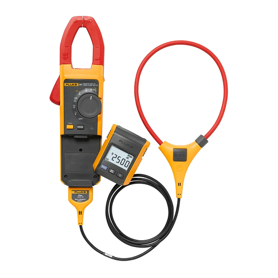
XWWarning Read "Safety Information" before you use the Meter. The Fluke 381 is a handheld, battery-operated Clamp Meter (the Meter) that has a remote-display module and detachable iFlex (Flexible Current Probe). The Remote Display can be removed from the Meter body and read away from the measurement source. This lets the display be easily read in difficult-measurement situations such as a hazardous environments, or very tight spaces. -
Page 6: Safety Information
Users Manual Singapore: +65-738-5655 Anywhere in the world: +1-425-446-5500 Or, visit Fluke's website at www.fluke.com. To register your product, visit http://register.fluke.com. To see, print, or download the latest manual supplement, visit http://us.fluke.com/usen/support/manuals. Safety Information A Warning identifies conditions and actions that pose hazard(s) to the user; A Caution identifies conditions and procedures that could cause Meter damage, equipment under test damage, or permanent loss of data. - Page 7 Remote Display True-rms Clamp Meter Safety Information Examine the test leads for damaged insulation or exposed metal. Check test lead continuity. Replace damaged test leads before using the Meter. Do not use the Meter if it operates incorrectly. Protection can be compromised. When in doubt, have the Meter serviced.
- Page 8 Users Manual Use extreme caution when working around bare conductors or bus bars. Contact with the conductor could result in electric shock. Adhere to local and national safety codes. Individual protective equipment must be used to prevent shock and arc blast injury where hazardous live conductors are exposed.
- Page 9 Hazardous voltage directives. Risk of Danger. Important Conforms to relevant North American information. See Manual. Safety Standards. Battery. Low battery when shown. Double insulated Do not dispose of this product as unsorted municipal waste. Go to Fluke’s website for recycling information.
- Page 10 Users Manual Symbol Meaning Symbol Meaning IEC Measurement Category III IEC Measurement Category IV CAT III equipment has protection CAT IV equipment has protection against transients in equipment in against transients from the primary CAT III CAT IV fixed-equipment installations, such supply level, such as an electricity as distribution panels, feeders and Meter or an overhead or underground...
-
Page 11: Radio Frequency Data
Changes or modifications to the wireless 2.4 GHz radio not expressly approved by Fluke Corporation could void the user's authority to operate the equipment. This device complies with Part 15 of the FCC Rules. Operation is subject to the two conditions that follow: This device can not cause interference. -
Page 12: Features
Users Manual off and on, the user is encouraged to try to correct the interference by one or more of the measures that follow: Reorient or relocate the receiving antenna. Increase the separation between the equipment and receiver. Consult the dealer or an experienced radio/TV technician for help. The term "IC:"... - Page 13 Remote Display True-rms Clamp Meter Features The Meter base and display can be a maximum of 10 meters from each other before the radio signal connection is broken. This distance can change with the obstacles between the Meter base and display. There is a radio connection when shows in the display. To detach the display from the Meter base, see Figure 1.
-
Page 14: Hazardous Voltage Indicator
Users Manual Hazardous Voltage Indicator When the Meter senses a voltage 30 V or a voltage overload (OL), Y is shown on the display and the red high-voltage LED () on the Meter base illuminates to tell you a hazardous voltage is at the Meter input. -
Page 15: Backlight
Remote Display True-rms Clamp Meter Features Backlight Push to toggle the Backlight on and off. The Backlight automatically goes off after 2 minutes. To disable the Backlight Auto Off feature, hold down while turning on the Meter. Display Hold To capture and hold the present display reading, push ... -
Page 16: Inrush
Users Manual Inrush Inrush Current is surge current that occurs when an electrical device is first powered on. The Meter can capture this surge current reading. Current spikes from motor drives are one example of such an event. The Inrush function takes approximately 400 samples over a 100 ms period and calculates the starting current envelope. - Page 17 Remote Display True-rms Clamp Meter Features ghn02.eps Figure 2. Meter Features...
- Page 18 Users Manual Table 2. Meter Features Item Description Current sensing Jaw Tactile Barrier Rotary Function Switch, see Table 3. Hazardous-voltage indicator Display release button Display Backlight button: turns the Backlight on and off. The Backlight stays on for 2 minutes when there is no button or switch interaction and then shuts off. Hold button: freezes the display reading and releases the reading when pushed a second time.
- Page 19 Remote Display True-rms Clamp Meter Features Item Description Zero/Shift button: removes dc offset from dc current measurements. Also used to shift and corresponds to the yellow items on the Rotary Function Switch. Inrush button: push to enter inrush mode. Push a second time to exit inrush mode. Integration time is 100 ms.
- Page 20 Users Manual Table 3. Rotary Function Switch Switch Position Function Meter is powered down AC voltage DC voltage Resistance and continuity AC current. Push Z to shift to frequency. DC current AC current and frequency measurement using the Flexible Current Probe. Push Z to shift to frequency.
-
Page 21: Display
Remote Display True-rms Clamp Meter Features Display To view all segments on the display at once, push H while turning the Meter on. See Figure 3 and Table 4. ghn01.eps Figure 3. Display... - Page 22 Users Manual Table 4. Display Item Description Item Description Inrush is active Meter base low-battery symbol Measurement is taken at the Hold is active Jaw. RF signal is being sent to Volts remote display. Amps Continuity Ohms, DC, AC, Hz Hazardous voltage is present.
-
Page 23: Measurements
Remote Display True-rms Clamp Meter Measurements Measurements Note Prior to first use, remove the battery isolator (small piece of plastic between the batteries and battery contacts). AC and DC Current (Jaw) XW Warning To avoid electric shock or personal injury: When making current measurements, disconnect the test leads from the Meter. - Page 24 Users Manual Note Before zeroing the Meter, make sure the Jaws are closed and there is no conductor inside the Jaw. To measure ac or dc current: Turn the Rotary Function Switch to the proper function. You should see X on the display, indicating that the measurement is coming from the Jaw.
- Page 25 Remote Display True-rms Clamp Meter Measurements 1000 V 600 V 1000 A ghn04.eps Figure 4. Current Measurement with Jaw...
-
Page 26: Ac Current (Flexible Current Probe)
Users Manual AC Current (Flexible Current Probe) XW Warning To prevent possible electrical shock or personal injury: Do not apply the Flexible Current Probe around or remove from HAZARDOUS LIVE conductors. Take special care during fitting and removal of the Flexible Current Probe. -
Page 27: Ac And Dc Voltage
Remote Display True-rms Clamp Meter Measurements Note When the measured current is < 0.5 A, the center dot in the display icon (X) will flash on and off. With current > 0.5 A, the center dot will be steady. Observe the current value on the Meter display. If the Flexible Current Probe does not perform as expected: Inspect the coupling system to make sure that it is connected and closed correctly or for any damage. - Page 28 Users Manual ghn09.eps Figure 5. Flexible Current Probe Connection...
- Page 29 Remote Display True-rms Clamp Meter Measurements ghn05.eps Figure 6. Measurement with Test Leads (AC Voltage Shown)
-
Page 30: Resistance/Continuity
Users Manual Resistance/Continuity To measure resistance or continuity: Turn the Rotary Function Switch to Remove power from the circuit being tested. Connect the black test lead to the COM terminal and the red test lead to the G terminal. Measure the resistance by touching the probes to the desired test points of the circuit. View the reading on the display. - Page 31 Remote Display True-rms Clamp Meter Measurements 100 ms 1000 V 600 V 1000 A 1000 V 600 V 1000 A INRUSH ghn11.eps Figure 7. Inrush Current Measurement...
-
Page 32: Frequency Measurement (Jaw And Flexible Current Probe)
Users Manual Frequency Measurement (Jaw and Flexible Current Probe) To measure frequency: Turn the Meter Rotary Function Switch to A or D if the Flexible Current Probe is being used for the measurement. Center the Jaw or Flexible Current Probe around the measurement source. Push Z on the Meter to shift to Hz. -
Page 33: Battery Replacement
Remote Display True-rms Clamp Meter Maintenance Battery Replacement To replace the batteries in the Meter body, see Figure 8: Turn the Meter OFF. Use a flat head screwdriver to loosen the battery compartment door screw on the Meter base, and remove the door from the case bottom. Remove the batteries. - Page 34 Users Manual ghn03.eps Figure 8. Battery Replacement...
-
Page 35: User-Replaceable Parts
User-Replaceable Parts User-Replaceable Parts Table 5. User-Replaceable Parts Description Qty. Fluke Part Number Battery, AAA 1.5 V 2838018 Battery Door - Display Module 3625529 Battery Door - Meter Base 3766406 Fluke 381 Remote Display 3766445 Soft Case 3752973 User Manual 3538357... -
Page 36: Specifications
Users Manual Specifications Electrical Specifications AC Current Via Jaw Range ............. 999.9 A Resolution ..........0.1 A Accuracy ..........2 % 5 digits (10-100 Hz) 5 digits (100-500 Hz) Crest Factor (50/60 Hz) ......3 @ 500 A 2.5 @ 600 A 1.42 @1000 A Add 2 % for C.F. - Page 37 Remote Display True-rms Clamp Meter Specifications AC Current via Flexible Current Probe Range .............999.9 A / 2500 A (45 Hz – 500 Hz) Resolution ..........0.1 A / 1 A Accuracy ..........3 % 5 digits Crest Factor (50/60Hz) ......3.0 at 1100 A 2.5 at 1400 A 1.42 at 2500 A Add 2 % for C.F.
- Page 38 Users Manual Position Sensitivity ghn12.eps Figure 9. Position Sensitivity...
- Page 39 Remote Display True-rms Clamp Meter Specifications Distance from i2500-10 Flex i2500-18 Flex Error Optimum 0.5 in (12.7 mm) 1.4 in (35.6 mm) 0.5 % 0.8 in (20.3 mm) 2.0 in (50.8 mm) 1.0 % 1.4 in (35.6 mm) 2.5 in (63.5 mm) 2.0 % Measurement uncertainty assumes centralized primary conductor at optimum position, no external electrical or magnetic field, and within operating temperature range.
- Page 40 Users Manual DC Voltage Range ............. 600.0 V /1000 V Resolution ..........0.1 V / 1 V Accuracy ..........1 % 5 digits Frequency – Via Jaw Range ............. 5.0 – 500.0 Hz Resolution ..........0.1 Hz Accuracy ..........0.5 % 5 digits Trigger Level ...........
-
Page 41: Mechanical Specifications
Remote Display True-rms Clamp Meter Specifications Frequency via Flexible Current Probe Range .............5.0 to 500.0 Hz Resolution ..........0.1 Hz Accuracy ..........0.5 % 5 digits Trigger Level ...........5 to 20 Hz, 25 A 20 to 100 Hz, 20 A 100 to 500 Hz, 25 A Resistance Range .............600 /6 k /60 k... -
Page 42: Environmental Specifications
Users Manual Flexible Current Probe Cable Length (head to electronics connector) ....1.8 m Environmental Specifications Operating Temperature......-10 C to +50 C Storage Temperature......-40 C to +60 C Operating Humidity ......... Non condensing (< 10 C) 90 % RH (at 10 C to 30 C) 75 % RH (at 30 C to 40 C) 45 % RH (at 40 C to 50 C) (Without Condensation) - Page 43 Remote Display True-rms Clamp Meter Specifications RSS-210 IC: 6627A-F381 Temperature Coefficients Add 0.1 x specified accuracy for each degree C above 28 C or below 18 C Wireless Frequency ........2.4 GHz ISM Band 10 meter range Safety Compliance........ANSI/ISA S82.02.01:2004 CAN/CSA-C22.2 No. 61010-1-04 IEC/EN 61010-1:2001 to 1000V CAT III, 600V CAT IV.
- Page 44 Users Manual...
Need help?
Do you have a question about the 381 and is the answer not in the manual?
Questions and answers