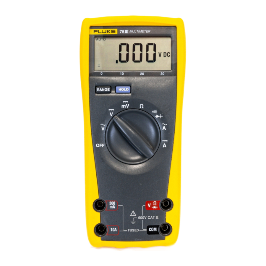
Fluke 77, 75, 73, 70, 23, 21 Manual
- Service manual (55 pages) ,
- User manual (38 pages) ,
- Calibration information manual (21 pages)
Advertisement
Specifications
 These service instructions are for use by qualified personnel only. To avoid electric shock, do not perform any servicing unless you are qualified to do so.
Accuracy is specified for a period of one year after calibration, at 18°C to 28°C (64°F to 82°F) with relative humidity to 90%. AC conversions are ac-coupled, average responding, and calibrated to the RMS value of a sine wave input. Refer to Table 1 for product specifications.
Accuracy specifications are given as: ±([% of reading] + [number of least significant digits])
Table 1. Specifications


PCA Access and General Maintenance

To avoid electrical shock, remove the test leads before opening the case, and close the case before operating the meter. To prevent fire, install fuses with the rating shown on the back of the meter.

To avoid contaminating the pca with oil from the fingers, handle it by the edges or wear gloves. Pca contamination may not cause immediate instrument failure in controlled environments. Failures typically show up when contaminated units are operated in humid areas.
Use the following procedure for removing the pca (printed circuit assembly) from its case:
- Set the function switch to OFF, and disconnect test leads if they are installed.
- Remove the four Phillips screws from the bottom cover.
- Turn the meter face up, grasp the top cover, and pull the top cover from the meter. For most models, this will best be accomplished by first lifting up the top cover at the input terminal end, followed by the display end.
- Some Series III Meters have a fuse on the lower portion of the pca. This fuse must be removed to access the screw that holds the pca to the case bottom.
- The pca may now be removed from the bottom cover.
Display Access
Do not handle the conductive edges of the LCD interconnects. If contaminated, clean with alcohol.
Refer to Figure 1 or 2 depending on the model.
- Remove the four Phillips screws from the back side of the pca.
- Remove the LCD mounting bracket.
- Insert a small screwdriver under the edges of the display holding bracket, and gently pry the bracket loose from the snaps.
- Turn the bracket upside down to remove the LCD.
- Before installing a new LCD, make sure that all connector contact points are clean.

Figure 1. 70/73 Assembly Details

Figure 2. 77/75/23/21 Assembly Details
Cleaning
To avoid damaging the meter, do not use aromatic hydrocarbons or chlorinated solvents for cleaning. These solutions will react with the plastics used in instruments.
Do not allow the LCD to get wet. Remove the display assembly before washing the pca and do not install until the pca is completely dry.
Do not use detergent of any kind for cleaning the pca.
Do not remove lubricants from the switch when cleaning the pca.
Clean the instrument case with a mild detergent and water.
The pca may be washed with isopropyl alcohol or deionized water and a soft brush. Remove the display assembly and fuses before washing, and avoid washing the switch if possible. Dry the pca with clean dry air at low pressure, then bake it at 50°C for 24 hours.
Performance Tests
The performance tests are recommended as a preventive maintenance tool to verify proper instrument operation. A one year calibration cycle is recommended to maintain the specifications given. Test equipment required for the performance tests and calibration is listed in Table 2. If the recommended equipment is not available, instruments with equivalent specifications may be used.
Table 2. Recommended Test Equipment
| Instrument Type | Recommended Model |
| Multi-Product Calibrator | Fluke 5500A |
Performance tests are recommended for incoming inspection, periodic maintenance, and for verifying the specifications. If the instrument fails any part of the test, calibration and/or repair is indicated.
In the performance tests, the Series III Meters are referred to as the unit under test (UUT).
Initial Procedure
- Allow the UUT to stabilize to room temperature 23°C ± 5°C (73°F ± 9°F).
- Check the fuses and battery, and replace them if necessary.
To prevent fire, install fuses in accordance with the rating shown on the back of the meter.
Display Test (70/73 Series III below s/n 80810247 only)
To test the display, turn the UUT on and check whether all display segments come on as indicated in Figure 3.

Figure 3. Display - 70/73 Series
Display Test (21/23/75/77 Series III only)
To test the display, press the range and hold buttons while turning the UUT on and check whether all display segments come on as indicated in Figure 4.

Figure 4. Display - 21/23/75/77 Series III
DC Voltage Test
Connect the ground/common/low side of the DC calibrator to COM on the UUT.
- Set the UUT function switch to VDC, and connect the DC Voltage Calibrator output to the
![]() and COM input terminals of the UUT.
and COM input terminals of the UUT. - Referring to Table 3, set the DC Voltage Calibrator for the output indicated in steps 1 through 5 only. Verify that the UUT display reading is within the limits shown.
- Set the DC Voltage Calibrator for an output of +300 mV, and switch the UUT to the 300 mV function.
Verify that the UUT display reading is within the limits shown in Table 3 (step 6).
 and COM input terminals of the UUT.
Table 3. DC Voltage Test
| Step | DC Input Voltage | Model | |
| 70, 73, 75, 21 | 77,23 | ||
| 1 | +2.7V | 2.691 to 2.709V DC | 2.691 to 2.709V DC |
| 2 | +27V | 26.91 to 27.09V DC | 26.91 to 27.09V DC |
| 3 | +270V | 269.1 to 270.9V DC | 269.1 to 270.9V DC |
| 4 | +600V | 597 to 603V DC | |
| 5 | +1000V | N/A | 995 to 1005V DC |
| 6* | +300 mV | 299.0 to 301.0 mVDC | 299.0 to 301.0V DC |
*300 mV function only
AC Voltage Test
Connect the ground/common/low side of the AC calibrator to COM on the UUT.
- Set the UUT function switch to VAC, and connect the AC Voltage Calibrator to the and COM input terminals.
- Set the AC Voltage Calibrator for the output given in Table 4, verify that the UUT display reading is within the limits shown.
Note
When the input is open in the VAC function, it is normal for the Series III Meters to read some counts on the display. This is due to ac pickup in the ac amplifier when the ac amplifier is unterminated.
Table 4. AC Voltage Test
| Input | Display Reading | |||
| Step | Voltage | Frequency | 70, 73, 75, 21 | 77,23 |
| 1 | 2.7V | 100 Hz | 2.644 to 2.756V AC | 2.644 to 2.756V AC |
| 2 | 2.7V | 500 Hz | 2.644 to 2.756V AC | 2.644 to 2.756V AC |
| 3 | 600V | 100 Hz | 586 to 614V AC | |
| 4 | 600V | 1 kHz | 586 to 614V AC | |
| 5 | 1000V | 100 Hz | N/A | 978 to 1022 |
| 6 | 1000V | 1 kHz | N/A | 978 to 1022 |
Resistance Test
- Select the ohms function on the UUT.
- Connect the Ohms Calibrator or Decade Resistor to the
![]() and COM input terminals of the UUT.
and COM input terminals of the UUT. - Referring to Table 5, set the Ohms Calibrator or Decade Resistor to the resistance value indicated in steps 1 through 7. Verify that the display reading is within the limits shown.
 and COM input terminals of the UUT.
Table 5. Resistance Test
| Step | Input Resistance | Display Reading | |
| 70, 73, 21, 75 | 23, 77 | ||
| 1 | short | 0.0 to 0.2Ω | 0.0 to 0.3Ω |
| Decades of 1: | |||
| 2 | 100Ω | 99.3 to 100.7Ω (plus 0 reading) | 99.2 to 100.8Ω (plus 0 reading) |
| 3 | 1kΩ | 994 to 1006 Ω | 994 to 1006 Ω |
| 4 | 10 kΩ | 9.94 to 10.06 kΩ | 9.994 to 10.06 kΩ |
| 5 | 100 kΩ | 99.4 to 100.6 kΩ | 99.94 to 100.6 kΩ |
| 6 | 1 MΩ | .994 to 1.006 MΩ | .994 to 1.006 MΩ |
| 7 | 10 MΩ | 9.79 to 10.21 MΩ | 9.79 to 10.21 MΩ |
| Decades of 1.9: | |||
| 2 | 190Ω | 188.8 to 191.2Ω (plus 0 reading) | 188.7 to 191.3Ω (plus 0 reading) |
| 3 | 1.9 kΩ | 1889 to 1911 Ω | 1889 to 1911 Ω |
| 4 | 19 kΩ | 18.89 to 19.11 kΩ | 18.89 to 19.11 kΩ |
| 5 | 190 kΩ | 188.9 to 191.1 kΩ | 188.9 to 191.1 kΩ |
| 6 | 1.9 MΩ | 1.889 to 1.911 MΩ | 1.889 to 1.911 MΩ |
| 7 | 19 MΩ | 18.61 to 19.39 MΩ | 18.61 to 19.39 MΩ |
| Decades of 2.7: | |||
| 2 | 270Ω | 268.4 to 271.6Ω (plus 0 reading) | 268.3 to 271.7 Ω (plus 0 reading) |
| 3 | 2.7 kΩ | 2685 to 2715Ω | 2685 to 2715Ω |
| 4 | 27 kΩ | 26.85 to 27.15 kΩ | 26.85 to 27.15 kΩ |
| 5 | 270 kΩ | 268.5 to 271.5 kΩ | 268.5 to 271.5 kΩ |
| 6 | 2.7 MΩ | 2.685 to 2.715 MΩ | 2.685 to 2.715 MΩ |
| 7 | 27 MΩ | 26.45 to 27.55 MΩ | 26.45 to 27.55 MΩ |
Diode Test
To test the Series III Meters, perform the following steps:
- Set the UUT to the Diode Test function.
![warning]() Note
Note
On Fluke 5100 series calibrators, activate the 50 Ω divider override. On Fluke 5500A calibrators, lock voltage to the 33V range. - Apply an input from the DC Voltage Calibrator of +.090V dc to the
![]() and COM input terminals of the UUT, and verify that the beeper is on.
and COM input terminals of the UUT, and verify that the beeper is on. - Increase the DC Voltage Calibrator output to +.110V dc, and verify that the beeper is off.
DC mA Test (73/75/21 & 77/23 Only)
- Set the output of the DC Current Calibrator to zero, and connect it to the 300mA and COM input terminals of the UUT.
- Set the DC Current Calibrator to the output shown in Table 5, and verify that the UUT display reading is within the limits shown.
Table 5. DC mA Test
| Step | Input Current | Display Reading |
| 1 | +27 mA | 26.57 to 27.43 DC |
| 2 | +200 mA | 196.8 TO 203.2 DC |
DC Amps Test (21/23/73/75/77 Only)
- Set the DC Current Calibrator to standby and connect it to the 10A and COM input terminals of the UUT.
- Apply current as indicated in Table 6, and verify that the display reading is within the limits shown.
Table 6. DC Amps Test
| Step | Input Current | Display Reading |
| 1 | +10 dc | 9.83 to 10.17 DC |
Calibration
- Set the DC Voltage Calibrator to zero, and set the UUT to the VDC function.
- Remove the case top cover as previously described.
- Connect the DC Voltage Calibrator to the
![]() and COM input terminals of the UUT.
and COM input terminals of the UUT. - Set the DC Voltage Calibrator for an output of +3.000V dc, and adjust R8 for a display reading of +3.000V dc ±.001V.
Replaceable Parts
Table 7. User Replaceable Parts
| Item | P/N | Description | Where Used | |||
| 70 | 73 | 21,75 | 23,77 | |||
| F1* | 943121 | Fuse, 44/100 A (fast acting), 1000 VAC/DC Min Interrupt Rating 10 kA | x | |||
| F2* | 803293 | Fuse, 11A (fast acting), 1000 VAC/DC Min Interrupt Rating 17 kA | x | x | x | |
| F1* | 740670 | Fuse, 630 mA (fast acting), 250V Min Interrupt Rating 1500A or IEC 127-1 | x | x | ||
| 659128 | Bottom Case Assembly (Note 1) | x | x | |||
| 1646042 | Bottom Case Assembly (Note 2) | x | x | |||
| 659125 | Case top Assembly | x | ||||
| 659133 | Case top Assembly | x | ||||
| 649241 | Case Top Assembly (Note 1) | x | ||||
| 1646056 | Case Top Assembly (Note 2) | x | ||||
| 649233 | Case Top Assembly | x | ||||
| 648748 | Probe Holder | x | x | |||
| 648961 | Tilt Stand | x | x | |||
*For safety, use exact replacement
Note 1 = for s/n below 1646056
Note 2 = for sn above 1646056
How to Contact Fluke
To contact Fluke, call one of the following telephone numbers:
1-888-99FLUKE (1-888-993-5853) in U.S.A.
1-800-36-FLUKE (1-800-363-5853) in Canada
+31-402-678-200 in Europe
+1-425-446-5500 from other countries
e - mail: sales@alltest.net .
Or, visit Fluke's Web site at www.fluke.com.
Documents / Resources
References
Download manual
Here you can download full pdf version of manual, it may contain additional safety instructions, warranty information, FCC rules, etc.
Advertisement


Need help?
Do you have a question about the 77 and is the answer not in the manual?
Questions and answers