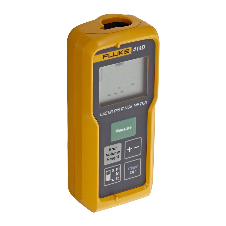
Fluke 414D, 419D, 424D - Laser Distance Meter Manual
- User manual (40 pages) ,
- Quick reference manual (2 pages) ,
- User manual (40 pages)
Advertisement
- 1 Introduction
- 2 Safety Information
- 3 Features
- 4 Before You Start
- 5 Batteries
- 6 Multifunctional Endpiece
- 7 Keypad
- 8 Display
- 9 Button Functions
- 10 On/Off
- 11 Basics
- 12 Units of Measurement
- 13 Timer (419D/424D)
- 14 Beeper (419D/424D)
- 15 Backlight (419D/424D)
- 16 Keypad Lock (419D/424D)
- 17 Compass (424D)
- 18 Compass Calibration
- 19 Magnetic Declination
- 20 Clear
- 21 Measurements with a Tripod
- 22 Reference Point
- 23 Measurements
- 24 Single Distance Measurement
- 25 Minimum/Maximum Tracking
- 26 Addition/Subtraction
- 27 Area
- 28 Volume
- 29 Tilt (424D only)
- 30 Stake Out Measurement (419D/424D)
- 31 Corner Angle Measurement (424D only)
- 32 Indirect Measurement
- 33 Memory (419D/424D)
- 34 Maintenance
- 35 Message codes
- 36 Specifications
- 37 How to Contact Fluke
- 38 Documents / Resources
Introduction
The Fluke 414D, 419D, 424D Laser Distance Meters (Meter or Product) are professional-grade laser distance meters. Use these Meters to quickly and accurately get the distance to a target, the area, and the volume measurements.
This Meter is better than an ultrasonic device because it uses laser light waves and measures their reflection.
The Meter includes:
- Most advanced technology for distance measurements
- More accurate measurement
- Longer measurement distance – model dependent
This manual identifies when a feature is model-dependent. If not identified, all models include the feature.
Safety Information
A

identifies hazardous conditions and procedures that are dangerous to the user.
To prevent eye damage and personal injury:
- Read all safety information before you use the Product.
- Carefully read all instructions.
- Use the Product only as specified, or the protection supplied by the Product can be compromised.
- Do not use the Product around explosive gas, vapor, or in damp or wet environments.
- Do not use the Product if it operates incorrectly.
- Do not use the Product if it is damaged.
- Disable the Product if it is damaged.
- Do not look into the laser. Do not point the laser directly at persons or animals or indirectly off reflective surfaces.
- Do not look directly into the laser with optical tools (for example, binoculars, telescopes, microscopes). Optical tools can focus the laser and be dangerous to the eye.
- Do not open the Product. The laser beam is dangerous to eyes. Have the Product repaired only through an approved technical site.
- Remove the batteries if the Product is not used for an extended period of time, or if stored in temperatures above 50°C. If the batteries are not removed, battery leakage can damage the Product.
- Replace the batteries when the low battery indicator shows to prevent incorrect measurements.
Table 1 is a list of symbols used on the Product and in this manual.
Table 1. Symbols
| Symbol | Description | Symbol | Description |
 | Consult user documentation. |  | Battery status. |
 | WARNING. RISK OF DANGER. |  | Battery or battery compartment. |
 | WARNING. LASER RADIATION. Risk of eye damage. |  | Conforms to relevant Australian Safety and EMC standards. |
 | Conforms to European Union directives. |  | Conforms to relevant South Korean EMC Standards. |
 | This product complies with the WEEE Directive marking requirements. The affixed label indicates that you must not discard this electrical/electronic product in domestic household waste. Product Category: With reference to the equipment types in the WEEE Directive Annex I, this product is classed as category 9 "Monitoring and Control Instrumentation" product. Do not dispose of this product as unsorted municipal waste. | ||
 | Indicates a Class 2 laser. The following text will appear with the symbol on the product label: "IEC/EN 60825-1. Complies with 21 CFR 1040.10 and 1040.11 except for deviations pursuant to Laser Notice 50, dated June 24, 2007." In addition, the following pattern on the label will indicate wavelength and optical power: λ = xxxnm, x.xxmW. | ||
Features
Table 2 is a list of features for the Meter by model.
Table 2. Model Feature Comparison
| Feature | 414D | 419D | 424D | Feature | 414D | 419D | 424D |
| Display Lines | 2 | 3 | 4 | Timer | • | • | |
| Memory [1] | 20 | 20 | Display/Keypad Illumination | • | • | ||
| Add/Subtract | • | • | • | Keypad Lock | • | • | |
| Area | • | • | • | Tripod Measurement | • | • | |
| Volume | • | • | • | Compass | • | ||
| Continuous Measurement | • | • | Triangular Area | • | |||
| Pythagoras Calculations | 1+2 | Full | Full | Smart Horizontal Mode (Tilt) | • | ||
| Stake Out [2] | • | • | Height Tracking | • | |||
| Multifunction Endpiece | • | • | Room Corner Angle | • | |||
| Beeper | • | • | Handstrap | • | • | • | |
| |||||||
Before You Start
This section has basic information about the batteries and measurement reference point. It also describes the Meter keypad and display.
Batteries
Replace the batteries when  blinks in the display.
To install or replace the batteries:
- Remove battery compartment lid. See Figure 1.

- Attach the handstrap.
- Install two AAA (LR03) batteries with the correct polarity.
![warning]() Note
Note
Do not use zinc-carbon batteries. - Close the battery compartment.

Multifunctional Endpiece
The 419D and 424D Meters adapt to multiple measurement situations with the multifunctional endpiece. See Figure 2:

- For measurements from an edge, fold out the endpiece (90 °) until it locks into place. See Figure 3.

- For measurements from a corner, fold out the endpiece (90 °) until it locks into place. Push the endpiece lightly to the right side to fold it out fully. See Figures 2 and 4.

- A built-in sensor automatically senses the orientation of the endpiece and adjusts the zero point.


Keypad
Figure 5 shows the location of each function button on the keypad.

- Measure/Power On
- Plus (+)/Minus (-)
- Plus (+)/Scroll Up
- Minus (-)/Scroll Down
- Clear/Off
- Reference/Change Units
- Area/Volume/Indirect Measurement (Pythagoras)
- Indirect Measurement (Pythagoras and Stake Out)
- Area/Volume
- Memory
- Timer
- Tilt
- Triangle
- Compass
Display
Figure 6 shows the readout location on the display for each function.

- Battery Status
- Info
- Area/Volume
- Measurement Reference
- Min/Max Measurement (Tracking Mode)
- Measurement Readout
- Units of Measurement
- Pythagoras
- Memory
- Circumference
- Wall Area
- Addition/Subtraction
- 2nd Result Available
- Stake Out
- Tilt Angle
- Slope Distance
- Indirect Height
- Ceiling Area
- Timer/Compass (424D only)
- Leveling
- Triangle Area
Button Functions
This section is about how to use the buttons and identifies when a function is model-dependent. When not identified, all models include the function.
On/Off
Push ![]() to turn on the Meter and laser. The display shows the battery symbol until you push a different button.
to turn on the Meter and laser. The display shows the battery symbol until you push a different button.
Push  for 2 seconds to turn off the meter.
Note
The Meter turns off automatically if not used in 180 seconds.
Basics
414D
Measure Button
Push ![]() :
:
- 1x = Laser on
- 2x = Measure
In Pythagoras calculation mode: - 2 seconds = Tracking (min/max measurement)
Function Buttons
Push ![]() :
:
- 1x = Area
- 2x = Volume
- 3x = Pythagoras 1
- 4x = Pythagoras 2
419D/424D
Measure Button
When off, push ![]() for 2 seconds = Continuous Laser On
for 2 seconds = Continuous Laser On
Push ![]() :
:
- 1x = Laser On
- 2x = Measure
- 2 seconds = Tracking (min/max measurement)
Function Buttons
Push  :
:
- 1x = Pythagoras 1
- 2x = Pythagoras 2
- 3x = Pythagoras 3
- 4x = Stake Out (419D: 1 value / 424D: 2 values)
Push  :
:
- 1x = Area
- 2x = Volume
- 2 seconds = 2nd Results
424D Only
Push  :
:
- 1x = Smart Horizontal Mode
- 2x = Height Tracking
- 3x = Leveling
Push  :
:
- 1x = Room Corner Angle (Triangular Area)
- 2 seconds = 2nd Results
Units of Measurement
Push and hold (414D) or
 ![]() (419D/424D) for 2 seconds to toggle between the units for distance measurements. See Table 3.
(419D/424D) for 2 seconds to toggle between the units for distance measurements. See Table 3.
Table 3. Units of Measurement
| 414D | 419D/424D  |
| 0.000 m | 0.000 m |
| 0 00' 1/16* | 0.0000 m |
| 0 in 1/16 | 0.00 m |
| * Default | 0.00 ft |
| 0'00' 1/32* | |
| 0.000 in | |
| 0 in 1/32 | |
| * Default |
Timer (419D/424D)
Fluke recommends that you use a time-delay for the most accurate measurements at long distances. This prevents Meter movement when you push ![]() .
.
To turn on the timer:
- Push
![]() 1x to turn on the 5-second timer. This is the default time interval to release the laser for a measurement.
1x to turn on the 5-second timer. This is the default time interval to release the laser for a measurement. - Push
![]() to increase up to 60 seconds.
to increase up to 60 seconds. - Push
![]() to decrease the seconds.
to decrease the seconds. - Push
![]() to begin the timer.
to begin the timer.
The seconds until measurement (for example, 59, 58, 57...) show as a countdown. The last 5 seconds count down with a beep. After the last beep, the Meter makes the measurement and the value shows on the display.
 1x to turn on the 5-second timer. This is the default time interval to release the laser for a measurement.
 to increase up to 60 seconds.
 to decrease the seconds.
 Note
The timer is useful for all measurements.
Beeper (419D/424D)
Push  at the same time for 2 seconds to turn on and turn off the beeper. The display shows the status as
  or
or  .
.
Backlight (419D/424D)
Push  at the same time for 2 seconds to turn on and turn off the backlight. The display shows the status as
  or
or  .
.
Keypad Lock (419D/424D)
To lock:
- Push
![]()
![]() at the same time to lock the keypad.
at the same time to lock the keypad.
 at the same time to lock the keypad.
 To unlock:
- Push
![]() .
. - Push
![]() within 2 seconds to unlock the keypad.
within 2 seconds to unlock the keypad.
 within 2 seconds to unlock the keypad.
Compass (424D)
The compass feature lets you know the view or direction as you make measurements. This is useful indoors to set the building plans in the correct direction. It is also useful to know the correct direction when you calculate the efficiency for a solar panel.
 Tips:
Tips:
- Make sure that the endpiece is folded in.
- When you use the compass feature, the Meter shows the calibration message. See Compass Calibration for more information.
- Compass arrows blink on the display if the Meter is tilted >20 ° end to end or >10 ° side to side. • When you turn on the compass, the Meter shows the calibration message. See Manual Calibration for more information.
Push  :
:
- 1x = Arrow points in north direction
- 2 seconds = Arrow points in direction of Laser beam and display shows the direction in degrees and an alpha symbol.

To prevent incorrect direction readouts, do not use near magnets and magnetic devices.
Compass Calibration
Automatic Calibration
The compass sensor continuously collects and saves new calibration values in 60-second intervals.
Manual Calibration
When you turn on the compass, the Meter shows the calibration message:
- For no, push
![]() . The compass uses old data that can be inaccurate.
. The compass uses old data that can be inaccurate. - For yes, push
![]() .
.
To continue with the calibration: - Rotate the Meter 180 ° around the Z-axis. See Figure 7.

- Rotate the Meter 180 ° around the X-axis.
- Rotate the Meter 180 ° around the Y-axis.
 . The compass uses old data that can be inaccurate.
 .
. 
The Meter counts from 1 to 12 during calibration.  shows on the display when the calibration is complete.
Magnetic Declination
The difference between the north geographic pole and the north magnetic pole is known as magnetic declination, or more plainly, declination. The angle of declination is different at different locations on the earth. The geographic and magnetic poles are aligned so declination is minimal. From some locations, the angle between the two poles can be fairly large.
Table 4 is a list of the current angles of declination by location. For other declination values, contact your local Geomagnetic Institute.
To set the Meter with the correct compensation for your location:
- Push
![]() at the same time.
at the same time.
The display shows![]() and the current setting. The default value is 0 °.
and the current setting. The default value is 0 °. - Push
![]() and
and ![]() to change the value.
to change the value. - Push
![]() to accept the new value.
to accept the new value.
 at the same time.
  and the current setting. The default value is 0 °.
 and
and  to change the value.
 to accept the new value.
Table 4. Estimated Values of Magnetic Field
| Country | City | Declination in Degrees (+E | -W) | Country | City | Declination in Degrees (+E | -W) | Country | City | Declination in Degrees (+E | -W) |
| Argentina | Buenos Aires | -7 | Greenland | Godthab | -29 | Spain | Madrid | -1 |
| Australia | Darwin | 3 | Iceland | Reykjavik | -15 | Switzerland | Zurich | 1 |
| Australia | Perth | -1 | Italy | Rome | 2 | Thailand | Bangkok | 0 |
| Australia | Sidney | 12 | India | Mumbai | 0 | Ukraine | Donetsk | 7 |
| Austria | Vienna | 3 | Japan | Tokyo | -7 | UAE | Dubai | 1 |
| Brazil | Brasilia | -20 | Kenya | Nairobi | 0 | United Kingdom | London | -1 |
| Brazil | Rio de Janeiro | -22 | Norway | Oslo | 2 | USA | Anchorage | 18 |
| Canada, BC | Vancouver | 17 | Panama | Panama | -3 | USA | Dallas | 3 |
| Chili | Santiago de Chile | 2 | Russia | Irkutsk | -3 | USA | Denver | 8 |
| China | Beijing | -6 | Russia | Moscow | 10 | USA | Honolulu | 9 |
| Egypt | Cairo | 3 | Russia | Omsk | 11 | USA | Los Angeles | 12 |
| France | Paris | 0 | Senegal | Dakar | -8 | USA | Miami | -6 |
| Germany | Berlin | 2 | Singapore | Singapore | 0 | USA | New York | -13 |
| Greece | Athens | 3 | South Africa | Cape Town | -24 | Venezuela | Caracas | -11 |
Clear
Push :
- 1x = Clear last value
- 2x = Clear all
- 2 seconds = Turn off Meter
Measurements with a Tripod
Measurements with the 419D and 424D that use a tripod must have the tripod reference set. When set, ![]() shows on the display.
shows on the display.
Reference Point
The display shows the reference point for a measurement. The default reference point is from the end of the Meter. If the beeper is on, the Meter beeps as you change the reference point. See Figure 8 for more information.

414D
Push  1x to change the reference point between the front and the end of the Meter. The display shows
 ![]() or
or ![]() .
.
419D/424D
The Meter automatically adjusts the reference point when you use the endpiece and ![]() shows on the display.
shows on the display.
Push ![]() :
:
- 1x = Measure from front
![]()
- 2x = Measure from tripod screw
![]()
- 3x = Measure from end
![]()
Note
The tripod mode overrides other reference points. The Meter stays in the tripod mode until you change to a different reference point.
Measurements
The Meter measures the distance to a target, the area bounded by two distances, or the volume in three measurements. This manual identifies when a feature is model-dependent. When not identified, all models include the feature.
Single Distance Measurement
To measure distance:
- Push
![]() to turn on the laser.
to turn on the laser. - Push
![]() again to make the distance measurement.
again to make the distance measurement.
The measurement shows on the display.
Note
Measurement errors can occur if you point the laser at colorless liquids, glass, Styrofoam, semi-permeable surfaces, and high-gloss surfaces. The measurement time increases when you point the laser at dark surfaces.
A target plate is useful for long distance measurements if the target reflectivity and illumination is a problem.
Minimum/Maximum Tracking
The tracking function measures the room diagonal (maximum value) and the horizontal distance (minimum value) from a stable measurement point. It also can find the distance between objects. See Figure 9.
![]()
To measure:
- Push and hold
![]() for 2 seconds.
for 2 seconds.
![]() shows on the display to confirm that the Meter is in tracking mode.
shows on the display to confirm that the Meter is in tracking mode. - Move the laser side to side, up and down on the target area (for example, into the corner of a room).
- Push
![]() to stop tracking mode.
to stop tracking mode.
 shows on the display to confirm that the Meter is in tracking mode.
The last measured value shows in the summary line.
Note
419D/424D Only: The values for maximum and minimum distances show in the display. The last measured value shows in the summary line.
Addition/Subtraction
The Meter adds and subtracts a value to a single distance, area, and volume measurements.
414D
To add or subtract:
Push  :
:
- 1x = Add the next measurement
- 2x = Subtract the next measurement
419D/424D
To add or subtract:
- Push
![]() to add the next measurement to the previous measurement.
to add the next measurement to the previous measurement. - Push
![]() to subtract the next measurement from the previous measurement.
to subtract the next measurement from the previous measurement. - Do these steps again for each measurement.
The total measurement result is always shown in the summary line with the value before in the second line. - Push
![]() to cancel the last step.
to cancel the last step.
 to add the next measurement to the previous measurement.
 to subtract the next measurement from the previous measurement.
Area
To measure area:
414D
- Push
![]() 1x. The
1x. The ![]() symbol appears in the display.
symbol appears in the display. - Push
![]() to make the first measurement (for example, length).
to make the first measurement (for example, length). - Push
![]() again to make the second measurement (for example, width).
again to make the second measurement (for example, width).
 symbol appears in the display.
The result shows in the summary line.
419D/424D
To measure area:
- Push
![]() 1x. The
1x. The ![]() symbol shows in the display.
symbol shows in the display. - Push
![]() to make the first measurement (for example, length).
to make the first measurement (for example, length). - Push
![]() again to make the second measurement (for example, width).
again to make the second measurement (for example, width).
The result shows in the summary line. - Push
![]() and hold for 2 seconds to get the 2nd result as a circumference.
and hold for 2 seconds to get the 2nd result as a circumference.
 1x. The
  symbol shows in the display.
 and hold for 2 seconds to get the 2nd result as a circumference.
Volume
414D
To measure volume:
- Push
![]() 2x. The
2x. The ![]() symbol shows in the display.
symbol shows in the display. - Push
![]() to make the first length measurement (for example, length).
to make the first length measurement (for example, length). - Push
![]() again to make the second length measurement (for example, width).
again to make the second length measurement (for example, width). - Push
![]() again to make the third length measurement (for example, depth).
again to make the third length measurement (for example, depth).
 symbol shows in the display.
The result displays in the summary line.
419D/424D
To measure volume:
- Push
![]() 2x. The
2x. The ![]() symbol appears in the display.
symbol appears in the display. - Push
![]() to make the first measurement (for example, length).
to make the first measurement (for example, length). - Push
![]() again to make the second measurement (for example, height).
again to make the second measurement (for example, height). - Push
![]() again to make the third length measurement (for example, depth).
again to make the third length measurement (for example, depth).
The result shows in the summary line. - Push
![]() x 2 seconds to show additional room information such as ceiling/floor area, surface area of the walls, circumference.
x 2 seconds to show additional room information such as ceiling/floor area, surface area of the walls, circumference.
![]() Ceiling/floor area (424D)
Ceiling/floor area (424D)
![]() Wall area (419/424)
Wall area (419/424)
![]() Circumference (419D/424D)
Circumference (419D/424D)
 2x. The
  symbol appears in the display.
 Ceiling/floor area (424D)
 Wall area (419/424)
 Circumference (419D/424D)
Tilt (424D only)
Note
The inclinometer senses tilts at 360 °. For tilt measurements, hold the Meter without a transverse tilt (±10 °).
Smart Horizontal Mode (424D only)
The Smart Horizontal mode (indirect horizontal distance) function lets you find a horizontal distance when the line-of-sight is blocked by an object or obstacle. See Figure 10 for more information.
")
The tilt is continuously shown as ° or %. To change the units, push and hold  at the same time for 2 seconds. The default unit is °.
To measure:
- Push
![]() 1x = Smart Horizontal Mode.
1x = Smart Horizontal Mode. ![]() shows in the display.
shows in the display. - Point laser at target.
- Push
![]() . The display shows all results as α (angle
. The display shows all results as α (angle ![]() ), x (diagonal distance
), x (diagonal distance ![]() ), and y (vertical distance
), and y (vertical distance ![]() ). The z (horizontal distance) shows in the summary line.
). The z (horizontal distance) shows in the summary line. - Push
![]() to turn off Smart Horizontal Mode.
to turn off Smart Horizontal Mode.
 1x = Smart Horizontal Mode.
  ), and y (vertical distance
  ). The z (horizontal distance) shows in the summary line.
 to turn off Smart Horizontal Mode.
Height Tracking (424D only)
Height tracking shows continuously on the display as the Meter turns on a tripod. The tilt is continuously shown in the selected unit of measure as ° or %.
To measure:
- Push
![]() 2x = Height tracking.
2x = Height tracking. ![]() shows in the display.
shows in the display. - Point the laser at lower target.
- Push
![]() .
. ![]() shows in the display with the distance and angle to the lower target.
shows in the display with the distance and angle to the lower target. - Move the laser upwards to the top target. Height Tracking starts automatically. The display shows the angle to the actual target and the vertical distance from the lower target.
- Push
![]() at the top target. Height Tracking stops and the display shows the vertical distance between the two measured targets. See Figure 11 for more information.
at the top target. Height Tracking stops and the display shows the vertical distance between the two measured targets. See Figure 11 for more information.
")
 shows in the display.
 shows in the display with the distance and angle to the lower target.
 Note
The minimum/maximum tracking is very helpful for 90 ° angle measurements. See Minimum/Maximum Tracking.
Leveling
The Leveling function continuously shows the angle of the Meter. From an angle of ±5 °, the Meter starts to beep. As it gets near ±1 °, the Meter beeps faster. At ±0.3 °, the Meter beeps constantly.
To level:
- Push
![]() 3x = Leveling.
3x = Leveling. ![]() shows in the display.
shows in the display. - Put the Meter on object to do a test for level.
The angle continuously shows on the display as the object moves.
Tilt Sensor Calibration
To calibrate the tilt sensor:
- Push
![]()
![]() at the same time for 2 seconds.
at the same time for 2 seconds.
The display shows![]() message and the instructions for the first measurement. See Figure 12.
message and the instructions for the first measurement. See Figure 12.

- Put the Meter on a flat horizontal surface.
- Push
![]() .
.
The display shows the instructions for the subsequent measurement. - Turn the Meter horizontally 180 ° on the same flat horizontal surface.
- Push
![]() .
.
The display shows the instructions for the subsequent measurement. - Put the Meter upright on a flat horizontal surface.
- Push
![]() .
.
The display shows the instructions for the subsequent measurement. - Turn the upright Meter 180 ° on the same flat surface.
- Push
![]() .
.
The display shows the calibration results as![]() .
.
 message and the instructions for the first measurement. See Figure 12.
 .
.Stake Out Measurement (419D/424D)
A specific distance can be set in the Meter and used to mark off defined measured lengths. An example of this application is in the construction of wooden frames. See Figure 13 for more information.
")
Note
For best results, it is recommended to use the end reference point for a stake out measurement. See Reference Point.
419D (1 Value)
To find stake out distances with 1 value:
- Push
![]() 4x.
4x. ![]() shows on the display.
shows on the display. - Push
![]() and
and ![]() to increase and decrease the value that shows in the summary line.
to increase and decrease the value that shows in the summary line.
![warning]() Note
Note
Hold the buttons down to increase the rate of change for the values. - Push
![]() to accept the value.
to accept the value.
The display shows the stake out distance in the summary line between the stake out point and the Meter (rear reference). - Move the Meter slowly along the stake out line and the distance decreases on the display.
The arrows in the display indicate in which direction the Meter needs to be moved in order to achieve the defined distance.
![warning]() Note
Note
If the beeper feature is on, the Meter starts to beep at a distance of 0.1 m (4 in) from the next stake out point. As the Meter moves near to the stake out point, the beep changes and the arrows do not show on the display. - Push
![]() to stop the stake out function.
to stop the stake out function.
 4x.
4x.  and
and  to increase and decrease the value that shows in the summary line.
424D (2 Values)
You can enter two different distances (a and b) into the Meter and use them to mark off measured lengths, for example, in the construction of wooden frames.
To find stake out distances with 2 values:
- Push
![]() 4x.
4x. ![]() shows in the display.
shows in the display. - Push
![]() and
and ![]() to increase and decrease the values that shows on the display.
to increase and decrease the values that shows on the display.
The value (a), and the intermediate line that corresponds, blink on the display. - Push
![]() and
and ![]() to adjust the (a) value.
to adjust the (a) value.
![warning]() Note
Note
Hold the buttons down to increase the rate of change for the values. - Push
![]() to accept the (a) value.
to accept the (a) value. - Push
![]() and
and ![]() to adjust the (b) value.
to adjust the (b) value. - Push
![]() to accept the (b) value.
to accept the (b) value.
The display shows the stake out distance in the summary line between the stake out point (a and then b) and the Meter (rear reference). - Move the Meter slowly along the stake out line the displayed distance decreases.
The arrows in the display![]() indicate in which direction the Meter needs to be moved in order to achieve the defined distance (either a, or b).
indicate in which direction the Meter needs to be moved in order to achieve the defined distance (either a, or b).
![warning]() Note
Note
If the beeper feature is on, the Meter starts to beep at a distance of 0.1 m (4 in) from the next stake out point. As the Meter moves near to the stake out point, the beep changes and the arrows do not show on the display. - Push
![]() to stop the stake out function.
to stop the stake out function.
 4x.
4x.  and
and  to increase and decrease the values that shows on the display.
 and
and  to adjust the (b) value.
Corner Angle Measurement (424D only)
The Meter calculates the angles in a triangle with measurements from the three sides. As an example, use this function with a right-angle room corner. See Figure 14 for more information.
")
To make corner angle measurements:
- Push
![]() 1x.
1x. ![]() (room corner) shows in the display.
(room corner) shows in the display. - Put marks for the reference points to the right and left (d1/d2) of the angle for measurement.
- Push
![]() to make a measurement of the first side of the triangle (d1 or d2).
to make a measurement of the first side of the triangle (d1 or d2). - Push
![]() to make a measurement of the second side of the triangle (d1 or d2).
to make a measurement of the second side of the triangle (d1 or d2). - Push
![]() to make a measurement of the third side of the triangle (d3).
to make a measurement of the third side of the triangle (d3). - The result shows in the summary line as the room triangle area.
- Push
![]() for 2 seconds to get the second results as the angle between d1 and d2, the triangle circumference, and the area.
for 2 seconds to get the second results as the angle between d1 and d2, the triangle circumference, and the area.
 1x.
1x.  (room corner) shows in the display.
 for 2 seconds to get the second results as the angle between d1 and d2, the triangle circumference, and the area.
Indirect Measurement
The Meter can calculate distances with Pythagoras' theorem. With this function, you can find a distance with two auxiliary measurements, such as building height or width measurements. It is helpful to use a tripod for a height measurement that uses two or three measurements.
Note
Make sure that you use the correct sequence of measurement:
- All target points must be in a horizontal or vertical plane.
- For the best results, turn the Meter about a set point. An example of this is with the endpiece fully open and the Meter on a wall.
- Make sure that the first measurement and the measurement distance are at 90 ° angles.
- The minimum/maximum tracking is very helpful for 90 ° angle measurements. See Minimum/Maximum Tracking.
414D
To find a vertical distance with two measurements (Pythagoras 1):
- Push
![]() 3x.
3x. ![]() shows on the display.
shows on the display. - Point the laser at the first target (1). See Figure 15.
")
- Push
![]() for the first distance (diagonal) measurement.
for the first distance (diagonal) measurement. - Point the laser at the second target (2).
- Make sure that the Meter is perpendicular to the wall.
- Push
![]() for the second distance measurement.
for the second distance measurement.
The Meter shows the height in the summary line. The distance of the second measurement shows in the secondary line.
")
To find a total distance with three measurements (Pythagoras 2):
- Push
![]() 4x.
4x. ![]() shows on the display.
shows on the display. - Point the laser at the first target (1). See Figure 16.
")
- Push
![]() for the first distance (diagonal) measurement.
for the first distance (diagonal) measurement. - Point the laser at the second target (2).
- Make sure that the Meter is perpendicular to the wall.
- Push
![]() for the second distance.
for the second distance. - Point the laser at the third (3) target.
- Push
![]() for the third distance measurement.
for the third distance measurement.
The Meter shows the height in the summary line. The distance is the total vertical height from the first to last targets. The third measurement shows in the secondary line.
")
As an option, use the tracking mode on one or more targets.
To use tracking mode:
- Push and hold
![]() for 2 seconds to start tracking mode.
for 2 seconds to start tracking mode. - Move the laser side to side and up and down on the ideal horizontal target point.
- Push
![]() to stop the tracking mode.
to stop the tracking mode.
419D/424D
To find a distance with two measurements (Pythagoras 1):
- Push
![]() 1x.
1x. ![]() shows on the display.
shows on the display. - Point the laser at the top point (1). See Figure 15.
- Push
![]() .
. - Point the laser at the second target (2).
- Make sure that the Meter is perpendicular to the wall.
- Push
![]() for the second distance measurement.
for the second distance measurement.
The Meter shows the height in the summary line. The distance of the second measurement shows in the secondary line.
 1x.
1x. To find a total distance with three measurements (Pythagoras 2):
- Push
![]() 2x.
2x. ![]() shows on the display.
shows on the display. - Point the laser at the first target. See Figure 16.
- Push
![]() for the first distance (diagonal) measurement.
for the first distance (diagonal) measurement. - Point the laser at the second target (2).
- Make sure that the Meter is perpendicular to the wall.
- Push
![]() for the second distance.
for the second distance. - Point the laser at the third (3) target.
- Push
![]() for the third distance measurement.
for the third distance measurement.
The Meter shows the result in the summary line. The measured distance to the subsequent measurement shows in the second line.
To find a partial distance, see Figure 17, with three measurements (Pythagoras 3):

- Push
![]() 3x. The laser turns on and
3x. The laser turns on and ![]() shows on the display.
shows on the display. - Point at the top target (1).
- Push
![]() . The Meter stores this measurement value.
. The Meter stores this measurement value. - Point the laser at the second diagonal target (2).
- Push
![]() for the second distance measurement.
for the second distance measurement. - Make sure that the Meter is perpendicular to the wall.
- Push
![]() to trigger the bottom target (3) measurement.
to trigger the bottom target (3) measurement.
The result is the partial vertical distance between target 1 and target 2. The third measurement shows in the secondary line.
As an option, use the tracking mode on one or more targets.
To use tracking mode:
- Push and hold
![]() for 2 seconds to start tracking mode.
for 2 seconds to start tracking mode. - Move the laser side to side and up and down on the ideal horizontal target point.
- Push
![]() to stop the tracking mode.
to stop the tracking mode.
Memory (419D/424D)
You can recall a previous measurement from memory, for example, the height of a room. The Meter stores a maximum of 20 displays.
To recall:
- Push
![]() 1x.
1x. - Push
![]() and
and ![]() to move through the stored displays.
to move through the stored displays.
![]() and the memory ID show on the display.
and the memory ID show on the display. - Push
![]() for 2 seconds to use the value shown in the Summary line for further calculations.
for 2 seconds to use the value shown in the Summary line for further calculations.
 and
and  to move through the stored displays.
  and the memory ID show on the display.
To delete:
- Push
![]() and
and ![]() at the same time.
at the same time.
The Meter deletes all the stored values in memory.
Maintenance
Maintenance and calibration are not necessary for the Meter.
To keep the Meter in good condition:
- Remove dirt with a moist, soft cloth.
- Do not put in water.
- Do not use aggressive detergents or solutions.
Message codes
Table 5 is a list of all message codes that show on the display with InFo or Error.
Table 5. Message Codes
| Code | Cause | Remedy |
| 156 | Transverse tilt greater than 10 ° | Hold the Meter without a transverse tilt. |
| 162 | Calibration mistake | Make sure that the device is on a horizontal and flat surface. Do the calibration procedure again. If the code continues, contact Fluke. |
| 204 | Calculation error | Do the measurement again. |
| 252 | Temperature too high | Let the Meter cool down. |
| 253 | Temperature too low | Let the Meter warm up. |
| 255 | Received signal too low, measurement time too long | Change target surface (for example, white paper). |
| 256 | Received signal too high | Change target surface (for example, white paper) |
| 257 | Too much background light | Darken target surface. |
| 258 | Measurement outside of measurement range | Correct the range. |
| 260 | Laser beam interrupted | Do the measurement again. |
| Error | Hardware error | Turn on and turn off the device 2 to 3 times. If the symbol stays on the display, then your Meter is defective, contact Fluke. |
Specifications
| 414D | 419D | 424D | |
| Distance Measurement | |||
| Typical Measurement Tolerance[1] | ±2.0 mm (±0.08 in)[3] | ±1.0 mm (± 0.04 in)[3] | |
| Maximum Measurement Tolerance[2] | ±3.0 mm (±0.12 in)[3] | ±2.0 mm (±0.08 in)[3] | |
| Range at target plate | 50 m / 165 ft | 80 m / 260 ft | 100 m / 330 ft |
| Typical Range[1] | 40 m / 130 ft | 80 m / 260 ft | |
| Range at unfavorable condition[4] | 35 m / 115 ft | 60 m / 200 ft | |
| Smallest unit displayed | 1 mm / 1/16 in | 1 mm / 1/32 in | |
| ∅ laser point at distances | 6 mm @ 10 m / 30 mm @ 50 m / 60 mm @ 100 m 0.24 in @ 33 ft / 1.2 in @ 164 ft / 2.4 in @ 328 ft | ||
| Tilt measurement | |||
| Measurement tolerance to laser beam[5] | no | no | ±0.2 ° |
| Measurement tolerance to case[5] | no | no | ±0.2 ° |
| Range | no | no | 360 ° |
| Compass accuracy | no | no | 8 points (±22.5 °)[6] |
| General | |||
| Protection class | IP40 | IP54 | |
| Automatic laser off | 90 seconds | ||
| Automatic power off | 180 seconds | ||
| Battery life (2 x AAA) 1.5 V NEDA 24A/IEC LR03 | up to 3000 measurements | up to 5000 measurements | |
| Dimensions (H x W x L) | 11.6 cm x 5.3 cm x 3.3 cm (4.6 in x 2.1 in x 1.3 in) | 12.7 cm x 5.6 cm x 3.3 cm (5.0 in x 2.2 in x 1.3 in) | |
| Weight (with batteries) | 113 g (4 oz) | 153 g (5 oz) | 158 g (6 oz) |
| Temperature | |||
| Storage | -25°C to +70°C (-13°F to +158°F) | -25°C to +70°C (-13°F to +158°F) | |
| Operation | 0°C to +40°C (32°F to +104°F) | -10°C to +50°C (14°F to +122°F) | |
| Calibration cycle | Not applicable | Not applicable | Tilt and Compass |
| Maximum altitude | 3500 m | ||
| Maximum relative humidity | 85% at -7°C to 50°C (20°F to 120°F) | ||
| Safety | |||
| General | IEC 61010-1: Pollution Degree 2 | ||
| Laser | IEC 60825-1: Class 2, 635 nm, <1 mW | ||
| Max peak radiant output power | 0.95 mW | ||
| Wavelength | 635 nm | ||
| Pulse duration | >400 ps | ||
| Pulse repetition frequency | 320 MHz | ||
| Beam divergence | 0.16 mrad x 0.6 mrad | ||
| EMC International | IEC 61326-1: Industrial Electromagnetic Environment CISPR 11: Group 1, Class A | ||
| Group 1: Equipment has intentionally generated and/or uses conductively-coupled radio frequency energy that is necessary for the internal function of the equipment itself. Class A: Equipment is suitable for use in all establishments other than domestic and those directly connected to a low-voltage power supply network that supplies buildings used for domestic purposes. There may be potential difficulties in ensuring electromagnetic compatibility in other environments due to conducted and radiated disturbances.. KCC: Class A Equipment (Industrial Broadcasting & Communication Equipment) Class A: Equipment meets requirements for industrial electromagnetic wave equipment and the seller or user should take notice of it. This equipment is intended for use in business environments and not to be used in homes. USA (FCC): 47 CFR 15 subpart B. This product is considered an exempt device per clause 15.103. | |||
| |||
How to Contact Fluke
To contact Fluke, call one of the following telephone numbers:
- Technical Support USA: 1-800-44-FLUKE (1-800-443-5853)
- Calibration/Repair USA: 1-888-99-FLUKE (1-888-993-5853)
- Canada: 1-800-36-FLUKE (1-800-363-5853)
- Europe: +31 402-675-200
- Japan: +81-3-3434-0181
- Singapore: +65-6799-5566
- Anywhere in the world: +1-425-446-5500
Or, visit Fluke's website at www.fluke.com.
To register your product, visit http://register.fluke.com.
To view, print, or download the latest manual supplement, visit http://us.fluke.com/usen/support/manuals.

Documents / Resources
References
![www.fluke.com]() Fluke Corporation: Fluke Electronics, Calibration and Networks
Fluke Corporation: Fluke Electronics, Calibration and NetworksFluke Registration
![us.fluke.com]() Fluke Manuals: Discontinued Legacy and Current Product Manuals | Fluke
Fluke Manuals: Discontinued Legacy and Current Product Manuals | Fluke
Download manual
Here you can download full pdf version of manual, it may contain additional safety instructions, warranty information, FCC rules, etc.
Download Fluke 414D, 419D, 424D - Laser Distance Meter Manual
Advertisement


Need help?
Do you have a question about the 414D and is the answer not in the manual?
Questions and answers