Simplex 4007ES Panels Installation Manual
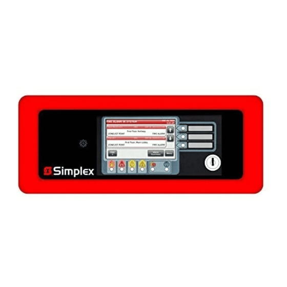
Color touchscreen lcd annunciator
Hide thumbs
Also See for 4007ES Panels:
- User manual ,
- Programmer's manual (168 pages) ,
- User & installation manual (44 pages)
Table of Contents
Advertisement
Quick Links
R
\
Cautions
READ AND SAVE THESE INSTRUCTIONS
and Warnings
must be followed to avoid damage to this product and associated equipment. Product operation and reliability depend upon
proper installation.
DO NOT INSTALL ANY SIMPLEX® PRODUCT THAT APPEARS DAMAGED
product, inspect the contents of the carton for shipping damage. If damage is apparent, immediately file a claim with the car-
rier and notify an authorized Simplex product supplier.
ELECTRICAL HAZARD
should be performed by a representative or authorized agent of your local Simplex product supplier.
FCC RULES AND REGULATIONS – PART 15
pursuant to Part 15 of the FCC Rules. These limits are designed to provide reasonable protection against harmful interference when the equipment is
operated in a commercial environment. This equipment generates, uses, and can radiate radio frequency energy and, if not installed and used in accor-
dance with the instruction manual, may cause harmful interference to radio communications. Operation of this equipment in a residential area is likely to
cause harmful interference in which case the user will be required to correct the interference at his own expense.
Introduction
The Color Touchscreen LCD Annunciator for 4007ES panels* provides remote annunciation of
the Fire Alarm Control Panel (FACP) status. Visual status is provided by the touchscreen and by
the LEDs. Audible annunciation is provided through a piezo sounder. Access to Annunciator
switch functions can be enabled or locked using the keyswitch. A maximum of six color
touchscreen annunciators can be installed on a 4007ES panel.
* 4007ES panels include the 4007ES hybrid panels and the 4007ES panels with IDNAC
notification. From this point on, they will be referred to as 4007ES.
Compatibility
The 4007ES panel needs to be at revision 3.02.07 or higher to support the Color Touchscreen
LCD Annunciator.
The following annunciators, boxes, and brackets are compatible with 4007ES panels:
Part Number
4606-9202
4606-9205
2975-9461
2975-9462
2975-9463
2975-9464
In this
Reference Documents ................................ 1 Wire Length Tables ..................................... 5
publication
Module Overview ........................................ 2 Communication Wiring Length Tables ........ 6
General Mounting Information .................... 3 Address Setting ........................................... 6
General Wiring Guidelines .......................... 3 Mounting Instructions .................................. 8
Specific Wiring Guidelines .......................... 3 Verification Procedure ................................. 8
Wiring .......................................................... 4 Remote Annunciator Specifications ............ 9
Reference
Refer to the following documents for more information on how to program and use the remote
annunciator.
Documents
Document Number
579-1165
579-1167
© 2015 Tyco Fire Protection Products. All rights reserved. Specifications and other information shown were current as of publication and
are subject to change without notice.
TYCO, SIMPLEX, and the product names listed in this material are marks and/or registered marks. Unauthorized use is strictly prohibited.
Document: Installation Manual
Part:
Color Touchscreen LCD Annunciator
Product:
4007ES Panels
-
Follow the instructions in this installation manual. These instructions
- Disconnect electrical field power when making any internal adjustments or repairs. All repairs
- This equipment has been tested and found to comply with the limits for a Class A digital device
Description
Color Touchscreen LCD Annunciator, Red
Color Touchscreen LCD Annunciator, Platinum
Color Touchscreen LCD Annunciator, Surface Mount Box, Red
Color Touchscreen LCD Annunciator, Surface Mount Box, Platinum
Color Touchscreen LCD Annunciator, Retrofit, Semi-flush bracket, Red
Color Touchscreen LCD Annunciator, Retrofit, Semi-flush bracket, Platinum
Title
4007ES Operator's manual
4007ES Programmer's manual
- Upon unpacking your Simplex
579-1172
Rev. A
Advertisement
Table of Contents

Related Manuals for Simplex 4007ES Panels


Summary of Contents for Simplex 4007ES Panels
- Page 1 © 2015 Tyco Fire Protection Products. All rights reserved. Specifications and other information shown were current as of publication and are subject to change without notice. Rev. A TYCO, SIMPLEX, and the product names listed in this material are marks and/or registered marks. Unauthorized use is strictly prohibited.
- Page 2 Color Touchscreen LCD Annunciator Installation Instructions, Continued Module Refer to Figure 1 for the remote annunciator front view and to Figure 2 for the back layout. Overview Bi-Color User Defined LEDs Slide-in Labels Piezo Touchscreen Keyswitch Fire LED Power LED Alarm Silenced LED Priority 2 LED Trouble LED...
- Page 3 1. Simplex Model 2081-9044 overvoltage protectors (200 mA or less): - There are no restrictions on wire routing, however, the maximum wire length is 2500 feet. 2. Simplex Model 2081-9027 (200 mA maximum) or Model 2081-9028 (5-amp maximum) isolated loop circuits protectors: - For underground wiring, select the appropriate isolated loop circuit protector.
- Page 4 Color Touchscreen LCD Annunciator Installation Instructions, Continued Wiring Note: To prevent Electrostatic Discharge (ESD), use a wrist strap assembly that connects to ground. Ensure power is OFF before installing or servicing the annunciator. To properly install the remote annunciator: 1. Terminate the annunciator’s RUI communication and power lines (Figure 3). OUT IN - COMM + COMM...
-
Page 5: Wire Length Tables
Color Touchscreen LCD Annunciator Installation Instructions, Continued Wire Length Table 2 and Table 3 show the maximum wire lengths possible for the power wiring. Table 4 and Tables Table 5 shows the maximum wire lengths for the communication wiring. • When using multiple annunciators and runs, the total of all runs must not exceed 10,000 ft. -
Page 6: Communication Wiring Length Tables
Color Touchscreen LCD Annunciator Installation Instructions, Continued Communication Table 4. With 2081-9044 Overvoltage Protectors Wiring Length 12 AWG (3.309 mm²) 14 AWG (2.801 mm²) 16 AWG (1.309 mm²) 18 AWG (0.823 mm²) Tables 2,500 ft. 2,500 ft. 2,450 ft. 1,650 ft. (762 m) (762 m) (746.76 m) -
Page 7: Address Setting
Color Touchscreen LCD Annunciator Installation Instructions, Continued Address Setting Table 6. Address Chart Address SW 2-2 SW 2-3 SW 2-4 SW 2-5 SW 2-6 SW 2-7 SW 2-8 Address SW 2-2 SW 2-3 SW 2-4 SW 2-5 SW 2-6 SW 2-7 SW 2-8... -
Page 8: Verification Procedure
Color Touchscreen LCD Annunciator Installation Instructions, Continued Mounting 1. Using the four provided screws, mount the annunciator in its back box (see Figure 6 for semi- Instructions flush mounting and Figure 7 for surface mounting). 2. Label the separate user-defined labels with the appropriate designation. 3. -
Page 9: Remote Annunciator Specifications
Color Touchscreen LCD Annunciator Installation Instructions, Continued Remote Table 7. Remote Annunciator Specifications Annunciator Operating Conditions: Specifications Operating Temperature Range 32 F - 120 F (0 C-49 Operating Humidity Range Up to 93% relative humidity at 100 F (38 C), non-condensing. Power Supply 24 VDC Nominal/18 VDC minimum at power input terminals of annunciator to allow for wiring losses. - Page 10 579-1172 Rev. A...
Need help?
Do you have a question about the 4007ES Panels and is the answer not in the manual?
Questions and answers