Advertisement
Quick Links
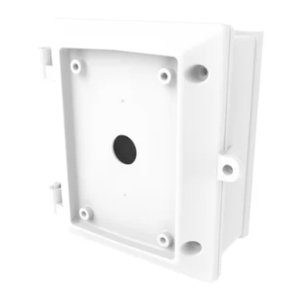
Quick Guide: Installation of V1001-JB with V1001-PL/V1001-CM/V1001-WM
1 – Fixed plate
1 – Cable gland
(pre-installed)
2 – Hex head wrench
1 – Rubber grommet
4 – M8 washer
4 – M8 20mm hex head
screw
4 – M8 20mm round
head screw
Package Contents
Installation Hardware
Step 2
Remove the junction box cover. Secure the pole mount to the pole or the
corner mount to the installation surface. Insert M8 20mm round head
screws on back of the junction box and latch them onto fixed plate.
Vicon part number 8009-8343-40-00
Vicon and its logo are registered trademarks of Vicon Industries Inc. All rights reserved.
Product specifications subject to change without notice.
Step 1
Use the screws included in the accessory package for the junction box to secure the fixed
plate on the pole or corner mount or the wall mounting surface (for wall mount).
Step 3
Tighten the captive 4x M8 35mm hex head
screws in the junction box.
Advertisement

Related Manuals for Vicon V1001-PL


Summary of Contents for Vicon V1001-PL
- Page 1 Vicon part number 8009-8343-40-00 Vicon and its logo are registered trademarks of Vicon Industries Inc. All rights reserved. Product specifications subject to change without notice.
- Page 2 Step 4 Step 5 Step 6 Route cables into the junction Route the cables through the wall mount. Route cables through one of the cable box and terminate cables. Secure the wall mount to the junction holes on black rubber grommet. If cable box cover using four stainless steel diameter is more than 7 mm, cut a line from anchors and M8 20mm hex head screws.
Need help?
Do you have a question about the V1001-PL and is the answer not in the manual?
Questions and answers