Advertisement
Quick Links
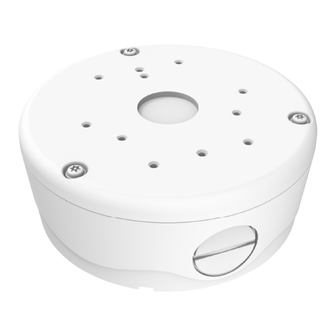
Wall & Surface Mount with Junction Box Kit
V2000B-BOX
For V2000B Bullet & V2360W Panoramic
Cameras
Quick Guide
1.
Product Overview
Ø5.8 (147)
Unit: in. (mm)
Ø5.8 (147)
F
1-1: P
D
IGURE
HYSICAL
IMENSION
Screw & Waterproof Rubber Sealing Instruction
Since the junction box supports multiple devices, it is recommended
to review the following diagram carefully, which depicts different
screw types and waterproof rubber bushing for each device, prior to
installation.
M4X14mm screw
M4X5mm screw
F
IGURE
1-2: S
CREW
T
YPES
I
LLUSTRATION
For V2000B bullet camera
For V2360W
panoramic camera
(Recommended
cable diameter no
less than 5mm)
F
1-3: W
R
B
I
IGURE
ATERPROOF
UBBER
USHING
LLUSTRATION
2.
Installation and Mounting
Package Content
Check if all items listed below are included in the packing box.
⚫ One adaptor plate
⚫ Two waterproof bushings
⚫ One holding bracket plate
⚫ One junction box
⚫ One torx wrench
⚫ One mounting template
⚫ One printed quick guide
⚫ Six TP4 tapping screws
⚫ Six screw anchors
⚫ Three M2.6X5mm screws
⚫ Four M4X5mm screws (for V2360W Panoramic)
⚫ Six M4X14mm screws (for V2000B Bullet)
Required Tools
The following tools might help during the installation:
⚫ A drill
⚫ A hammer
⚫ A Phillips head screwdriver
⚫ Wire cutters
Installation & Mounting Procedure
1.
Drill 6 holes on wall or surface based on the mounting
template. Diameter φ3/8" (9.5mm), depth 1/1/2" (40mm).
2.
Hammer the 6 screw anchors into the drilled holes.
3.
Fix the junction box onto the wall/surface by fastening the 6 TP4
tapping screws with the 6 screw anchors.
F
IGURE
2-1: F
IX
J
UNCTION
B
OX
3.
Mounting Procedure
For IR Bullet Camera
1.
Pass the camera cable through the adaptor plate, and then
secure the camera to the adaptor plate by fastening the 6
M4X14mm screws.
F
IGURE
3-1: S
ECURE
C
AMERA WITH
A
DAPTOR
P
LATE
2.
From the rear, cover the cable with the waterproof rubber
bushing and fasten them to the holding bracket plate using 3
M2.6X5mm screws onto the proper hole.
Waterproof Rubber Bushing
Waterproof Rubber Sealing
Holding Bracket Plate
F
3-2: C
T
P
IGURE
ABLE
HREAD
REPARATION
3.
Place the cable inside the junction box to connect with required
cables coming from either the bottom or side conduit hole of
the camera, depending on type of application, and attach the
junction box with the adaptor plate by fastening the
3 T20 screws with T20 torx wrench.
Be sure that unused ¾ NPT hole
is sealed with the supplied cap.
F
IGURE
3-3: A
SSEMBLE
\
JUNCTION BOX WITH ADAPTOR PLATE
4.
Finally, install the mounting kit with camera onto a wall or
surface.
F
IGURE
3-4: M
OUNTING COMPLETE
Advertisement

Related Manuals for Vicon V2000B-BOX


Summary of Contents for Vicon V2000B-BOX
- Page 1 Mounting Procedure For V2000B bullet camera Wall & Surface Mount with Junction Box Kit V2000B-BOX Place the cable inside the junction box to connect with required For IR Bullet Camera cables coming from either the bottom or side conduit hole of...
- Page 2 3-6: S IGURE ECURE DAPTOR LATE ON UNCTION Copyright ©2020 Vicon Industries Inc. All rights reserved Secure the bracket on adapter plate by fastening the 4 M4X5mm screws, and then push the cable into junction box. 3-7: S IGURE ECURE THE...
Need help?
Do you have a question about the V2000B-BOX and is the answer not in the manual?
Questions and answers