Table of Contents
Advertisement
Quick Links
INSTRUCTIONS FOR
INSTALLATION AND OPERATION
MODEL V1600WM
The information in this instruction manual covers the
installation of Model V16OOWM
door Wall Mount. This unit should only be installed by
a qualified technician using approved materials in ac-
cordance with national, state and local codes. Read these
instructions completely before attempting installation.
All Vicon equipment is tested and inspected before
leaving the factory. It is the carrier's responsibility to
deliver the equipment in the same condition as it left the
factory.
2.1.1 INSPECTION FOR VISIBLE DAMAGE
Immediately inspect the cartons upon delivery. Make a
note of any visible damage on all copies of the carrier's
freight bill.
Make sure the carrier's agent (the person making the
delivery) signs the note on all copies of the bill. If the agent
does not have claim forms, contact the carrier's office.
Product specifications subject to change without notice.
TOLL FREE: l-800-645-91 16 . UK: 44/(O) 1489/566300
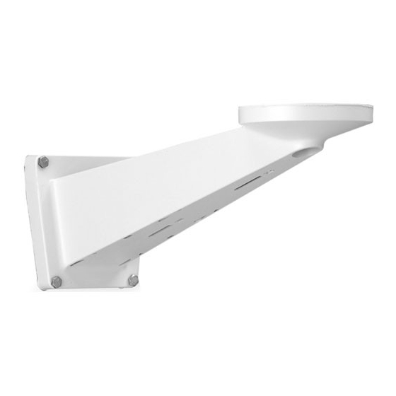
MEDIUM-DUTY OUTDOOR WALL MOUNT
Medium-Duty Out-
2. INSTALLATION
2.1 Unpacking and Inspection
The V16OOWM Medium-Duty Outdoor Wall Mount is
designed to support camera stations weighing up to a
total of 40 pounds (18 kg), including pan-and-tilt or
scanner, camera/lens system, and housing. It is con-
semigloss enamel finish. This wall mount accepts an
optional adjustable head, Model V1600AH, and a vari-
ety of pan-and-tilt drives and scanners.
2.1.2 INSPECTION FOR CONCEALED
DAMAGE
As soon as possible after delivery, unpack the unit and
inspect it for concealed damage. Do not discard the carton
or packing materials. If the unit is damaged, contact the
carrier immediately and request forms for filing a damage
claim. Make arrangements for a representative of the
carrier to inspect the damaged equipment.
If the equipment must be returned for repair, follow the
Shipping Instructions at the end of this manual.
(2288)
INFOFAX: I -800-287-l 207
l
Vicon part number 8006-8457-03-00
FAX: 516-951 -CCTV (2288)
l
Advertisement
Table of Contents

Related Manuals for Vicon V1600WM


Summary of Contents for Vicon V1600WM
- Page 1 2. INSTALLATION 2.1 Unpacking and Inspection 2.1.2 INSPECTION FOR CONCEALED All Vicon equipment is tested and inspected before DAMAGE leaving the factory. It is the carrier’s responsibility to deliver the equipment in the same condition as it left the As soon as possible after delivery, unpack the unit and factory.
- Page 2 The stainless steel threaded end into the bottom of the V1600WM, upwards through the hole in the center of the mount. required to install the V1600AH on the V1600WM.
- Page 3 4.75 IN. 12.1 CM 16.3 IN. (41.4 CM) (0.79 CM) 2.6 IN. CABLE PORl 6.4 CM Figure 1 MOUNTING PLATE B A S E MOUNT Figure 2 Installation of the V1600AH Adjustable Head x457-997...
- Page 4 United Kingdom 4. Mark the R.A. number on the outside of the carton on the shipping label. Vicon and its logo are registered trademarks of Vicon Industries Inc. Copyright 0 1997 Vicon Industries Inc. All rights reserved. x457-997...
Need help?
Do you have a question about the V1600WM and is the answer not in the manual?
Questions and answers