
Subscribe to Our Youtube Channel
Related Manuals for El.Mo HERCOLA


Summary of Contents for El.Mo HERCOLA
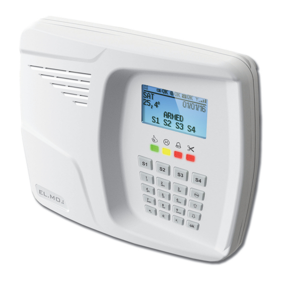
- Page 1 HERCOLA Wireless intrusion detection control unit with integrated GSM module 090060975 Compatible with the e-Connect platform...
- Page 2 (explosion and fire). EU DECLARATION OF CONFORMITY Hereby, EL.MO. S.p.A. declares that the HERCOLA radio equipment is in compliance with Directive 2014/53/EU. The full text of the EU declaration of conformity is available at the following internet address: elmospa.com – registration is quick and easy.
-
Page 3: Generals
HERCOLA can manage up to 32 radio zones and integrates a GSM module. It features a simplified configuration menu for local operations: the complete configuration can be set via software, either in direct or remote connec- tion, including through the e-Connect platform using the integrated GSM/GPRS module or the optional MDWIFIH module. - Page 4 HERCOLA - TECHNICAL MANUAL - 090060975 - 1000 event log (historic file). - Internal clock. - Weekly programmer. - Arming scenarios configuration and Max Security management. - Built-in chronothermostat with boiler failure detection and SMS-based remote control. - Connector for remote I66 proximity key readers.
-
Page 5: Electrical Features
Connector for electronic outputs. Parts supplied: the HERCOLA control unit is supplied with switching module already mounted and cabled, fixing screws and dowels for wall mounting, termination resistors for zones balancing (2 x 2.2K Ohm, 6 x 1.5K Ohm, 8 x 1.2K Ohm, 2 x 1K Ohm, 2 x 680 Ohm), user manual, quick guide, B0.812G backup battery provided in its... -
Page 6: Mechanical Features
HERCOLA - TECHNICAL MANUAL - 090060975 2.3 Mechanical features View of control unit dimensions: 2.4 General scheme international@elmospa.com elmospa.com... -
Page 7: Control Unit Installation
3.1 Control unit positioning We suggest that you place the HERCOLA control unit in a posi- tion as central as possible with respect to the devices to be con- trolled, in order to benefit from a higher radio signal level. -
Page 8: Control Unit Opening
HERCOLA - TECHNICAL MANUAL - 090060975 3.3 Control unit opening Push the locking tabs located on the lower side; lift the cover from the bottom up- wards, pivoting on the clips located on upper side. 3.4 Control unit closing Lean the front cover on the upper-side clips, then rotate it downwards until the two lower tabs click in position. -
Page 9: Wall Mounting Operations
090060975 - TECHNICAL MANUAL - HERCOLA 3.6 Wall mounting operations 1. The control unit can be wall-mounted. 2. Follow the measurements indicated in the picture below. Use the built-in spirit level for accurate horizontal alignment. Channels for the passage; of Clips for GSM antenna cables and cable feed holes. - Page 10 HERCOLA - TECHNICAL MANUAL - 090060975 10. If you want to install the optional MDWIFI module, pust it into its own connector according to the following figures: 11. locate the connector for the back up battery on the back. Connect the battery cable to the non-reversible connector and then place the backup battery in the dedicated position.
- Page 11 090060975 - TECHNICAL MANUAL - HERCOLA 13. pivot up the board, making sure that the MDWIFIH module (if installed) does not hit the inside of the back cover. 14. Lock the board under the flexible clips (indicated by the “...
-
Page 12: Electrical Connections
HERCOLA - TECHNICAL MANUAL - 090060975 4. ELECTRICAL CONNECTIONS 4.1 HERCOLA main board overview international@elmospa.com elmospa.com... -
Page 13: View Of Inner Side Of The Hercola Board
090060975 - TECHNICAL MANUAL - HERCOLA 4.2 View of inner side of the HERCOLA board 4.3 Wired zones wiring diagram for HERCOLA Note: if you configure triple-balanced operating mode for zones, use only good quality ca- bles. international@elmospa.com elmospa.com... -
Page 14: Fast Zones Wiring Diagram
HERCOLA - TECHNICAL MANUAL - 090060975 4.4 Fast zones wiring diagram 4.5 “Key” zones Every zone can be programmed as “Key Zone”. This option has to be enabled when the unit is interfaced with pulsed control devices equipped with terminal outputs only and not compatible with the unit (e.g. a radio receiver of a surveillance centre). -
Page 15: Sirens Wiring Diagram
090060975 - TECHNICAL MANUAL - HERCOLA 4.6 Sirens wiring diagram 4.7 Electronic outputs wiring diagram Note: enable outputs in advance in the “System options - Power saving - Enable Onboard Outputs” menu. Then, associate the specific event to the output you wish to use. -
Page 16: Wiring Diagram For Boiler Control
HERCOLA - TECHNICAL MANUAL - 090060975 4.8 Wiring diagram for boiler control Wiring diagram of the programmable relay output with chronothermostat function. Note: if the relay is used for chronothermostat function, it will not work according to positive logic mode... -
Page 17: I66 Readers Wiring Diagram
090060975 - TECHNICAL MANUAL - HERCOLA 4.10 I66 readers wiring diagram 4.10.1 Not compliant with EN50131 standard. Note: to connect I66 or I7 readers use the cable with 10-pole connector supplied with the unit. 4.10.2 Wiring diagram of I66 readers according to EN50131 standard... -
Page 18: Installation Of Sim Card To Gsm Module
“REGIST. MODULES” and “NETWORK PARAM.” keypad modules, then using Brow- serOne v. 3.5.3 or higher with the HERCOLA module v. 8.2.0 or higher. Lastly, the received e-Connect access code has to be typed in the “INTERNET ACCOUNT” keypad menu. The successful connection will be marked with a icon on the display. -
Page 19: System Reset
5. SYSTEM RESET 5.1 Default Reset Procedure The HERCOLA control unit is programmed with factory basic settings called Default settings. This setup enables proceeding with basic unit setup. Should it become necessary to delete new settings, return to the Default settings by following the procedure listed below: 5.1.1 If the unit is powered up for the first time... -
Page 20: Operating Mode With Default Setup
HERCOLA - TECHNICAL MANUAL - 090060975 5.2 Operating mode with default setup Zones to be wired to terminal board: IN1 and IN2. Tamper zone, balanced with 1500resistor. Zones configuration: NO for low-consumption mode. Zones connection: No zone connected. Active area: Zones configuration: All zones assigned to area 1 sectors. -
Page 21: Firmware Update
090060975 - TECHNICAL MANUAL - HERCOLA 6. FIRMWARE UPDATE As EL.MO. intrusion detection control unit, HERCOLA also features an extremely easy procedure for firmware update: the only necessary tools are a PC connected to the unit via USB cable and the management software. - Page 22 HERCOLA - TECHNICAL MANUAL - 090060975 5. Window listing available modules: 6. Select OK to select the module and display configuration windows. 7. Select Firmware Update menu: international@elmospa.com elmospa.com...
- Page 23 090060975 - TECHNICAL MANUAL - HERCOLA 8. The following window will display the sequence of operations for firmware selection: Press this key to sync with the online EL.MO. ar- chive. Select the firmware language. Press “Ok” to start the download.
- Page 24 HERCOLA - TECHNICAL MANUAL - 090060975 9. Open the unit housing, provide mains and battery supply, then connect the PC to the unit using USB-MINIUSB cable. 10. After pressing Next key in the previous windows, the kind of connection will be displayed together with possible warnings.
- Page 25 090060975 - TECHNICAL MANUAL - HERCOLA 12. By pressing Next again, the setup programme will give visual indications on how to move the jumpers on the unit board to imple- ment the update. 13. The following window shows how to close S6 jumper and press RESET button. To continue updating firmware, select Next.
-
Page 26: If The Control Unit Has Already Been Configured
HERCOLA - TECHNICAL MANUAL - 090060975 6.1.17 If the control unit has already been configured Preliminary steps: - Use BrowserOne to read the control unit configuration after selecting the appropriate software mod- ule (use one of the remote connection options provided by BrowserOne, or the e-Connect service platform, according to the module boards previously installed in the control unit). -
Page 27: Table Of Contents
........... . 12 4.2.View of inner side of the HERCOLA board . - Page 28 Wireless intrusion detection control unit with integrated GSM module mod. HERCOLA - TECHNICAL MANUAL July 2017 edition - v. 2.0 090060975 The information and product specification herein are not binding and may be changed without prior notice. EL.MO. SpA Via Pontarola, 70 - 35011 Campodarsego (PD) - Italy...
Need help?
Do you have a question about the HERCOLA and is the answer not in the manual?
Questions and answers