Table of Contents
Advertisement
Quick Links
Technical manual
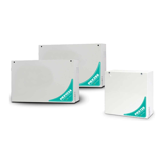
PROXIMA seRIes
Multi-functional hybrid intrusion
detection system control units
1
DesCRIPTION
PROXIMA is a series of multi-functional hybrid control units
that support both wired and wireless devices.
The PROXIMA control units support the connection of all
EL.MO. serial devices (keypads, proximity (key) readers,
power supply units, fog systems, concentrators and individ-
ual detectors) thanks to the ULTRABUS interface.
They are compatible with the first generation radio technol-
ogy through the use of RIVERRF concentrators and with the
NG-TRX radio technology after connecting a GATEWAY2K
over serial line.
Optional modules may be connected to expand its functions:
• MDGSME: it makes it possible to connect the control unit
to a GSM/GPRS network.
• MD4GE: makes it possible to connect the control unit to
a LTE network.
• MDPSTN: it makes it possible to connect the control unit
to an analogue telephone line.
• MDVOICE64: voice module; it makes it possible to record
up to 64 customised voice messages.
• MDRS232: allows interfacing to external devices via RS-
232 serial line.
The PROXIMA control units can be managed via keypad
menus and BrowserOne software.
You can also connect to e-Connect.
The PROXIMA control units are sold in a plastic housing pro-
tected against opening and removal from the wall.
The PROXIMA control units are certified IMQ - Security
Systems.
Refer to the instruction manual.
2
HARDWARe FeATURes
• On-board power source up to 5 A (of which 4 A available
at loads)
• Integrated 10/100 Mbps Ethernet module
• 1 USB device port + 1 USB host port
• 1 MicroSD card slot (up to 128 GB)
• 2 expansion slots for module housing
• 1 connector for speech synthesis module
• 1 key connector
• 1 generic expansion connector
• 2 output connectors for ETRREL
Removable terminals:
• 16 on-board inputs INGRESSI LINEE, (which can be ex-
panded to 32 using the split function), 12 fast inputs
• 2 independent outputs for sensor supply (ALIM. SENS. 1, 2)
• 2 independent RS-485 serial outputs ULTRABUS
(485-1, 485-2)
• 2 programmable 3 A relays (RELE' PROG 1, 2)
• 1 programmable output for controlling a power relay (P+)
• 1 Tamper input (TAMPER)
• SIR +, 14V for siren control and power supply (SIR+, 14V)
1 1 1
Advertisement
Table of Contents

Related Manuals for El.Mo PROXIMA Series


Summary of Contents for El.Mo PROXIMA Series
- Page 1 PROXIMA is a series of multi-functional hybrid control units that support both wired and wireless devices. The PROXIMA control units support the connection of all EL.MO. serial devices (keypads, proximity (key) readers, HARDWARe FeATURes power supply units, fog systems, concentrators and individ- ual detectors) thanks to the ULTRABUS interface.
-
Page 2: Pcb
MDGSME module slot 11 Terminal block 1 Expansion connector 12 Reset button Key connector 13 Backup battery (for clock maintenance) Speech synthesis connector 14 Terminal block 2 MDPSTN module slot 15 LAN connector ETRREL 1 electronic output expansion connector 16 USB connector ETRREL 2 electronic output expansion connector 17 USB mini-B connector MicroSD card slot module... -
Page 3: Technical Data
TeCHNICAL DATA Model PRX128 PRX256 PRX1024 General features No. of on-board wired zones 16 (32 with split function) Max. no. of supported zones 1024 Number of supported outputs (max) 1024 Max. no. of users 1024 Maximum number of controls 32 (of which a maximum of 32 advanced keyboards) Max no. - Page 4 Model PRX128 PRX256 PRX1024 No power source 12.8 No power source reset 13.5 Power consumption at 12V Control unit only (on or off) Relay ON GSM module enabled in voice mode GSM module enabled in GPRS mode GSM module, maximum power consumption Idle PSTN module PSTN module operating in digital...
-
Page 5: Before Installation
BeFORe INsTALLATION BrowserOne settings Enable all EN 50131 options in the unit on page System Options > General of BrowserOne. General warnings are at the end of this manual. Set the following "General options": • “Lock Dialler at Disarming Event” always OFF; •... -
Page 6: Classification Of Notifications
fault" events and associate them to fault contact in order Overvoltage protection is guaranteed by the power supply to have them processed as fault. unit (125%). • For each fault event, a notification must be triggered both 5.2.1 Classification of notifications when the system is armed and when it is disarmed. -
Page 7: Current Distribution For Imq - Security Systems
• SP5: LAN integrated on-board in SIA DC-09 e-Connect • An easily accessible disconnecting device must be protocol (periodic transmission 90 s); provided. • DP4: MDGSME or MDGSME90 or MD4GE and LAN inte- 5.3 Usage with NG-TRX devices grated on-board in SIA DC-09 e-Connect protocol (peri- odic transmission 90 s). - Page 8 • Fixing the container PRX128: side opening (rear view) 216 mm – feed 230 V mains cable through hole A 305 mm – feed system cables through holes B Note: the entry of the cables can also be done from the top PRX128: tilt opening (rear view) after drilling the container in the prepared areas.
-
Page 9: Prx256 - Prx1024
Tamper protection connection – open control unit door • Fixing the container PRX256 - PRX1024: tilt opening (rear view) 340 mm (*) tamper contacts of the devices – weld and insulate the two cables (one coming from the anti-opening switch, the other from the anti-tear switch) in point X in the figure –... - Page 10 after drilling the container in the prepared areas. metal plate • Wirings For precise engagement, use a screwdriver if necessary. – install any optional modules on the control unit board as indicated in chapter 7 p. 13 – fix the metal plate to the bottom of the container in the –...
-
Page 11: Rack Mounting
6.2.1 Rack mounting 6.3.2 MDGsMe and MD4Ge The container of PRX256 and PRX1024 supports rack Follow the instructions in the respective manuals. mounting. Installing the module When installed in a rack, the container can only be tilted. 19" brackets included in the optional PRXRACK kit are required. -
Page 12: Mdpstn
Nut (tighten with 8 mm spanner) – fasten the antenna by tightening the nut Note: See the MDPSTN technical manual. – cut the protection grommet along the indicated dashed lines – insert the grommet on the antenna 6.3.3 MDPsTN – insert the spacers (supplied) into the holes in the dedicat- ed area on the control unit board (D) If necessary, use pliers. -
Page 13: Wirings
WIRINGs Wired zone connection Connect all the required wired devices to inputs 1 to 16 on the control unit terminal block. Below are some examples of balancing and configuration of the main types of zones. A graphic editor is available in BrowserOne for each zone to freely configure the balances. -
Page 14: Extended Split Zones
Control unit Detector 1 Detector 2 Control unit = 1500 Ω Detector 1 = 2200 Ω Detector 2 = 1000 Ω – connect the two devices in parallel as shown in the figure = 1200 Ω = 680 Ω In BrowserOne: – go to page Zones > General –... -
Page 15: Key Zones
Control unit Generic control device with impulsive contact Tamper Contact (NA) Tamper Contact (NC) Device contact (NO) Control unit = 1500 Ω Roll-up shutter sensor Inertial contact – make the connections as shown in the figure (the con- Alarm contact nections shown also include the necessary protection Tamper contact against tampering) Two 1500 Ω... -
Page 16: Siren Connection
siren connection 7.2.2 Indoor sirens 7.2.1 Outdoor sirens NA NC C SIR+ SIR. TAMPER ALIM. 13.8V TAMPER RIF. ALIM. SIR.AA 13.8V Control unit Siren Tamper switches Control unit = 1500 Ω Siren Tamper switches – connect the indoor wired sirens as shown Manual contact for maintenance –... -
Page 17: Serial Line Devices
ALIM. SENS. 1000 Control unit Previous device over serial line Next device over serial line Control unit Keypad – connect each device to the serial line using terminals A I66 proximity (key) reader and B (in addition to the power source terminals) –... - Page 18 simple serial line AL M. SENS. External power source Control unit Serial line device 1 Serial line device 2 Also in this case, join together the negative references of central unit placed at a midpoint of the line the control unit and the remote box. central unit placed at one end of the line Each serial device (including the control unit) may be posi- tioned at any position of the bus.
-
Page 19: Addressing Of Concentrators
– go to page Zones > Cable Devices Branched serial line – select in the grid one of the lines relating to the bank of inputs to be reserved for the concentrator – from the drop-down menu Zone Type, select "Wired Concentrator"... - Page 20 Number of Dip on ON Number of Dip on ON Number of Dip on ON Number of Dip on ON addresses addresses addresses addresses 217 - 224 - - 3 - - 6 7 - 729 - 736 - - 3 - - 6 - - 25 - 28 1 - - 4 5 6 - - 153 - 156...
-
Page 21: Starting The Device
sTARTING THe DeVICe Number of Dip on ON Number of Dip on ON addresses addresses Once all the wiring has been completed and carefully 35 - 36 - 2 3 4 - 6 7 - 163 - 164 - 2 3 4 - 6 - - checked, power the control unit for the first time. -
Page 22: Browserone Software
– press OK to access a menu item, or STOP to exit – press and hold down the RESET button (see chapter For a full guide to the use of the keypad menus see the pro- 3 p. 2 ) gramming manual. –... -
Page 23: Firmware Update
9.2 Firmware update particular malfunctions – click on Next The control unit firmware may be updated to add new – select the voice module update mode (any messages re- functions. corded will not be cancelled) The update can occur in two situations: –... -
Page 24: Wireless Device Battery Change
User confirmation version 1.0.8. If it has been set that the update must be confirmed by the Note: In order to perform remote update, it is necessary to user, the user will have to: be enabled. – go to the keypad –... -
Page 25: Table Of Contents
Table of contents DESCRIPTION......P. 1 MAIN SAFETY RULES..... P. 28 HARDWARE FEATURES . -
Page 28: Eu Declaration Of Conformity
The information and product features herein are not binding and may be changed without prior notice. EL.MO. Spa - Via Pontarola, 70 - 35011 Campodarsego (PD) - Italy Ph. +39 049.9203333 - Fax +39 049.9200306 - Help Desk +39 049.9200426 - www.elmospa.com - international@elmospa.com...
Need help?
Do you have a question about the PROXIMA Series and is the answer not in the manual?
Questions and answers