
Related Manuals for Maxcess FIFE DP-20 PLUS


Summary of Contents for Maxcess FIFE DP-20 PLUS
- Page 1 FIFE GUIDING SOLUTIONS FIFE DP-20 PLUS Operating Instructions Web Guide Controller with operating unit Edition 10/2022 MI 1098 1...
- Page 2 When requesting service or spare parts, please have ready the following reference number. Bitte halten Sie bei Service- oder Ersatzteilanfragen die folgende Referenznummer bereit. Pour toute demande d’intervention ou de pièces détachées merci de nous communiquer la référence suivante. Si prega citare il seguente riferimento in caso di richiesta di assistenza tecnica o parti di ricambio.
-
Page 3: Table Of Contents
Display in the setup area ..........6-4 www.maxcess.com... - Page 4 3x.5.2 ASC Control ........... 9-52 MI 1098 1 DP-20 PLUS www.maxcess.com...
- Page 5 Addresses ............14-1 APPENDIX A - BASIC SETTINGS 15-1 APPENDIX B - MENUSTRUCTURE 16-1 www.maxcess.com DP-20 PLUS MI 1098 1...
-
Page 6: Introduction
For proper and safe use, the operating instructions must be read all persons and used by who have the responsibility of installing, commissioning, operating and maintaining the web guide controller. Keep for future reference. MI 1098 1 DP-20 PLUS www.maxcess.com... -
Page 7: Safety Instructions
The signal word CAUTION refers to a possible danger which could lead to slight to moderate injury. The signal word ATTENTION refers to a possible danger which could lead to material damage www.maxcess.com DP-20 PLUS MI 1098 1... -
Page 8: Symbols
Keep for future use. Additional markings – Bulleted list ∙ Instructions 1. Instructions which must be processed in the specified order 2. End of the instructions Reference or cross-reference Note: Reference to important information. MI 1098 1 DP-20 PLUS www.maxcess.com... -
Page 9: Personnel Requirements
These risks must be recorded in a risk assessment by the machine/system builder and taken into consideration in the operating instructions. www.maxcess.com DP-20 PLUS MI 1098 1... -
Page 10: Notes For Operating Personnel
∙ Danger of injury by crushing Do not place your hands on or near moving parts (rollers, web), during operation ∙ If the web guide controller is damaged while in use, it must be taken out of operation. MI 1098 1 DP-20 PLUS www.maxcess.com... -
Page 11: Maintenance
SAFETY INSTRUCTIONS 2 - 5 Maintenance ∙ Maintenance work must only be performed on the web guide controller when the power is turned off, and the machine has been stopped and secured against restart. www.maxcess.com DP-20 PLUS MI 1098 1... -
Page 12: Product Description
DP-20 PLUS are not permitted. Any other use of the DP-20 PLUS must be previously discussed with and approved by Fife-Tidland GmbH. Note: The DP-20 PLUS web guide controller must not be opened, any warranty claim expires. MI 1098 1 DP-20 PLUS www.maxcess.com... -
Page 13: Improper Usage
DP-30 and is to be installed compatible with regard to its mounting. Accessory Various sensors, drives or additional devices make it possible to adapt the DP-20 PLUS to an extremely wide variety of applications. www.maxcess.com DP-20 PLUS MI 1098 1... -
Page 14: Operating Principle
The guide rollers are then aligned parallel to the rollers of the customer system. Manual There is no guiding of the web course. The drive can be controlled manually with the ’+’ and ’-’ keys. MI 1098 1 DP-20 PLUS www.maxcess.com... -
Page 15: Installation
The electronic components may be damaged – Not in places where there is a risk of explosions. – Protect from falling objects The device can be damaged or an unintended switching process could be initiated. www.maxcess.com DP-20 PLUS MI 1098 1... -
Page 16: Dimensions Of The Dp-20 Plus
4 - 2 INSTALLATION Dimensions of the DP-20 PLUS Dimensions are given in mm. • • Rheinland UL/CSA 61010-1 IEC 61010-1 Slide bar Fastening screw Figure 4.1: Dimensions of the DP-20 PLUS MI 1098 1 DP-20 PLUS www.maxcess.com... -
Page 17: Mechanical Fastening
2. Connect all required cables to the DP-20 PLUS. 3. Place DP-20 PLUS into the cutout in the control panel. 4. Re-install Slide Bars and fastening screws. 5. Tighten fastening screws until the DP-20 PLUS is secure in the control panel. www.maxcess.com DP-20 PLUS MI 1098 1... -
Page 18: Wall Mount (Optional)
4. Tighten fastening screws until the DP-20 PLUS is secure in the bracket. 5. Mount the bracket firmly on a wall with the DP-20 PLUS. Figure 4.3: Front view of a DP-20 PLUS with a standard mounting frame MI 1098 1 DP-20 PLUS www.maxcess.com... - Page 19 INSTALLATION 4 - 5 • • Rheinland UL/CSA 61010-1 IEC 61010-1 Figure 4.4: Rear view of a DP-20 PLUS with a standard mounting frame Figure 4.5: Dimensions of the standard mounting frame www.maxcess.com DP-20 PLUS MI 1098 1...
-
Page 20: Replacement Dp-30 With Dp-20 Plus (Optional)
Figure 4.6: Front view of a DP-20 PLUS with a DP-30 compatible mounting frame • • Rheinland UL/CSA 61010-1 IEC 61010-1 Figure 4.7: Rear view of a DP-20 PLUS with a DP-30 compatible mounting frame MI 1098 1 DP-20 PLUS www.maxcess.com... - Page 21 INSTALLATION 4 - 7 Figure 4.8: DP-30 compatible mounting frame dimensions www.maxcess.com DP-20 PLUS MI 1098 1...
-
Page 22: Electrical Connection
0 to be realised in accordance with EN 60204-1. Relevant measures must be taken if the electromechanical drive is connected via an external output stage or if a hydraulic actuator is used. MI 1098 1 DP-20 PLUS www.maxcess.com... -
Page 23: Connecting The Sensors/Drives
It is NOT possible to set the sensor voltage for each sensor port separately. One of the connected sensors that is not suitable for 15V could be destroyed or its service life reduced. www.maxcess.com DP-20 PLUS MI 1098 1... - Page 24 Optional accessory device RGPC-40 Two RGPC-40 or combinatorial input by means of VTB-40(E) Sensor right edge Line sensor Sensor left edge Electrical power connection For technical details and additional information, please refer Technical Data MI 1098 1 DP-20 PLUS www.maxcess.com...
-
Page 25: Commissioning
There is danger from crushing and from cutting on the web material itself and/or from the movement of the web. During commissioning, do not touch or come close to moving parts (rollers, web). Do not touch the edges of the material web. www.maxcess.com DP-20 PLUS MI 1098 1... - Page 26 DP-20 PLUS. 10. Create backup It is recommended to save the settings of the DP-20 PLUS in a backup copy. 3x.3.2 Backup settings, page 9-37 MI 1098 1 DP-20 PLUS www.maxcess.com...
-
Page 27: Operation
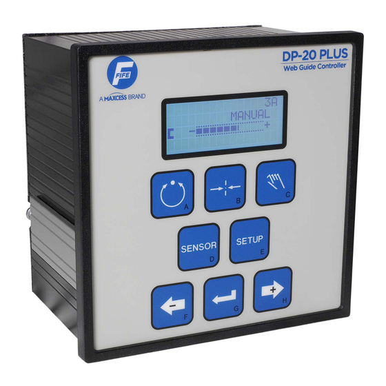
Do not touch the edges of the material web. User interface figure 6.1 The DP-20 PLUS control panel depicted in features 8 keys and an LCD display. Figure 6.1: Front side of the DP-20 PLUS controller with LCD display and keyboard www.maxcess.com DP-20 PLUS MI 1098 1... -
Page 28: User Area
You can use the Setup key to exit the user area and switch to the setup area. These settings can only be made with the DP-20 PLUS keys. MI 1098 1 DP-20 PLUS www.maxcess.com... -
Page 29: Keys And Their Functions
RGPC - Left Switch to a lower menu level Enter --- * or confirm entries Servo-center and Manual: Move drive Right arrow Change values or settings Automatic: RGPC - Right * --- No function www.maxcess.com DP-20 PLUS MI 1098 1... -
Page 30: Display In The User Area
3. Designation of the currently selected menu item in setup 4. Display of the settings for the currently selected menu item Figure 6.4: Display in the setup in setup area 5. Symbol of the active sensor/sensors, Symbols see above MI 1098 1 DP-20 PLUS www.maxcess.com... -
Page 31: Password Protection
The settings in these menus cannot be edited until the valid password has been entered. Ö× X3C.1.2.1 SETUP (MAN) GUIDE POINT The "X" is only displayed if a password has been assigned. -ØØØäØØØ+ 0.0% Figure 6.6: www.maxcess.com DP-20 PLUS MI 1098 1... -
Page 32: Menu Structure
2 - Servo-center 3 - Manual Sensor mode: A - Sensor edge left B - Sensor edge right C - Center guiding D - Line center E - Line edge F - Servo-center transducer MI 1098 1 DP-20 PLUS www.maxcess.com... - Page 33 This position in the menu identification changes depending on the sensor mode present in the custo- mer’s installation. Center guiding with the sensor mode “C” is used as an example in the displays in these sections. www.maxcess.com DP-20 PLUS MI 1098 1...
-
Page 34: Menus - Automatic Operating Mode
The gain and offset parameters can be viewed and their values can be modified. Note: All changes take effect immediately after they have been entered, even before saving. MI 1098 1 DP-20 PLUS www.maxcess.com... -
Page 35: 1X.1 Gain
SETUP (AUTO) GAIN áØØØØØØØØØ ∙ Enable the menu for editing Input Ö× 1C.1.1 SETUP(AUTO) GAIN áØØØØØØØØØ ∙ Increase (H key) or reduce (F key) the gain with the arrow keys ∙ Save or cancel entries www.maxcess.com DP-20 PLUS MI 1098 1... -
Page 36: 1X.2 Guide Point
0.0% ∙ move the guide point with the arrow keys ∙ Reset the offset of the guide point to 0.0% by pressing both arrow keys at the same time. ∙ Save or cancel entries MI 1098 1 DP-20 PLUS www.maxcess.com... -
Page 37: 1X.3 Measurement
¢£ SENSOR (X2) presettings made in the factory or from the calibration of the -ááááØØØØ servo center transducer. The connected motor is displayed, Ö× 3C.1.8.3 Drives, page 12-5 MEASUREMENT ¢£ SENSOR (X2) -ááááØØØØ www.maxcess.com DP-20 PLUS MI 1098 1... - Page 38 The status of the digital output ( page 12-4 Parallel input matrix, ) and the digital input ( page 12-4 ) is displayed. ∙ Exit the menu using the last menu item in any menu item with the C key MI 1098 1 DP-20 PLUS www.maxcess.com...
-
Page 39: 1X.4 About
DEFAULT. The state machine (SM) number of the DP-20 PLUS is displayed. If the DP-20 PLUS has not been specially programmed, this is indicated in the display by the word NONE. www.maxcess.com DP-20 PLUS MI 1098 1... - Page 40 7 - 7 MENUS - AUTOMATIC OPERATING MODE ∙ Exit the menu using the last menu item in any menu item with the C key MI 1098 1 DP-20 PLUS www.maxcess.com...
-
Page 41: Menus - Servo-Center Operating Mode
If the DP-20 PLUS is password protected, the values of parameters that are shown in gray in the menu structure page 16-1 ( ) will not be changed until after the password is entered. www.maxcess.com DP-20 PLUS MI 1098 1... -
Page 42: Gain
ßØØØØØØØØØ ∙ Enable the menu for editing Input Ö× 2C.1.1 SETUP (SC) ¢£ GAIN ßØØØØØØØØØ ∙ Increase (H key) or reduce (F key) the gain with the arrow keys ∙ Save or cancel entries MI 1098 1 DP-20 PLUS www.maxcess.com... -
Page 43: Guide Point
0.0% ∙ move the guide point with the arrow keys ∙ Reset the offset of the guiding point to 0.0% by pressing both arrow keys at the same time ∙ Save or cancel entries www.maxcess.com DP-20 PLUS MI 1098 1... -
Page 44: 2X.3 Measurement
¢£ SENSOR (X2) presettings made in the factory or from the calibration of the -ááááØØØØ servo center transducer. The connected motor is displayed, Ö× 3C.1.8.3 Drives, page 12-5 MEASUREMENT ¢£ SENSOR (X2) -ááááØØØØ MI 1098 1 DP-20 PLUS www.maxcess.com... - Page 45 The status of the digital output ( page 12-4 Parallel input matrix, ) and the digital input ( page 12-4 ) is displayed. ∙ Exit the menu using the last menu item in any menu item with the C key www.maxcess.com DP-20 PLUS MI 1098 1...
-
Page 46: 2X.4 About
DEFAULT. The state machine (SM) number of the DP-20 PLUS is displayed. If the DP-20 PLUS has not been specially programmed, this is indicated in the display by the word NONE. MI 1098 1 DP-20 PLUS www.maxcess.com... - Page 47 MENUS - SERVO-CENTER OPERATING MODE 8 - 7 ∙ Exit the menu using the last menu item in any menu item with the C key www.maxcess.com DP-20 PLUS MI 1098 1...
-
Page 48: Menus - Manual Operating Mode
If the DP-20 PLUS is password protected, the values of parameters that are shown in gray in the menu structure page 16-1 ( ) will only be changed after entering the password. MI 1098 1 DP-20 PLUS www.maxcess.com... -
Page 49: 3X.1.1 Gain
∙ Enable the menu for editing Input Ö× 3C.1.1.1 SETUP (MAN) GAIN áØØØØØØØØØ ∙ Increase (H key) or reduce (F key) the gain with the arrow keys ∙ Save or cancel entries www.maxcess.com DP-20 PLUS MI 1098 1... -
Page 50: 3X.1.2 Guide Point
0.0% ∙ move the guide point with the arrow keys ∙ Reset the offset of the guide point to 0.0% by pressing both arrow keys at the same time ∙ Save or cancel entries MI 1098 1 DP-20 PLUS www.maxcess.com... -
Page 51: 3X.1.3 Guide Polarity
The polarity value is always displayed for the sensor type that is currently selected. ∙ Enable the menu for editing Input Ö× 3C.1.3.1 SETUP (MAN) GUIDE POLARITY ∙ Reverse the polarity (+ or -) with the arrow keys ∙ Save or cancel entries www.maxcess.com DP-20 PLUS MI 1098 1... -
Page 52: 3X.1.4 Calibration For Edge Sensors
Key sequence from the initial menu to the menu Ö× 3C.1.4 SETUP (MAN) CALIBRATION ∙ Enable the menu for editing Note: For center guiding, the following sequence must be performed for both the left and the right edge sensors. MI 1098 1 DP-20 PLUS www.maxcess.com... - Page 53 Note: The material web can be moved into the sensor’s field of vision with the plus and minus keys. ∙ Press the Enter key The reference value will be determined. www.maxcess.com DP-20 PLUS MI 1098 1...
- Page 54 If there is not enough contrast for control, “FAILED” appears in Ö 3A.1.4.6 the display. FAILED ßØØØØØØØØØ ∙ Cancel entries Calibration of the sensor must be repeated until the process can be successfully completed. MI 1098 1 DP-20 PLUS www.maxcess.com...
-
Page 55: 3X.1.4 Calibration For Line Sensors
Using the line sensors Depending on how the line sensors are used, the calibration differs for: – Tracking a line center ý – Tracking a material or printing edge §. www.maxcess.com DP-20 PLUS MI 1098 1... -
Page 56: Tracking A Line Center
-ßØØØØØØØØØ+ is located within the spot of light on the left border. 1 - Web 2 - Light spot ∙ Press the Enter key Wait a few seconds. The reference value will be determined MI 1098 1 DP-20 PLUS www.maxcess.com... - Page 57 If there is not enough contrast for control, “FAILED” appears in ü 3D.1.4.6 the display. FAILED ßØØØØØØØØØ ∙ Cancel entries Calibration of the sensor must be repeated until the process can be successfully completed. www.maxcess.com DP-20 PLUS MI 1098 1...
-
Page 58: Tracking A Material Or Printing Edge
To do this, the line sensor should be positioned so that the spot UNCOVER SENSOR -ßØØØØØØØØØ+ of light of the line sensor is completely on the background. 1 - Web 2 - Light spot MI 1098 1 DP-20 PLUS www.maxcess.com... - Page 59 If there is not enough contrast for control, “FAILED” appears in § 3E.1.4.6 the display. FAILED ßØØØØØØØØØ ∙ Cancel entries Calibration of the sensor must be repeated until the process can be successfully completed. www.maxcess.com DP-20 PLUS MI 1098 1...
-
Page 60: Tracking A Broken Line Centre
The ASC thresholds must be set to -90 % and +100% , page 9-54. If required, the negative value can be changed. ∙ The ASC source must be on the line edge, page 9-56 MI 1098 1 DP-20 PLUS www.maxcess.com... -
Page 61: 3X.1.4 Calibration Of The Servo-Center Transducer
∙ Enable the menu for editing Input Note: The servo-center transducer is identified by Sensor in the menus for calibration. ∙ Use the arrow keys to select: Servo-center transducer ¢£ (X2) ∙ Confirm entry www.maxcess.com DP-20 PLUS MI 1098 1... - Page 62 Manual operating mode. If there is not enough contrast, “FAILED” appears in the display ¢£ 3F.1.4.6 FAILED -ØØØØØØØØØØ+ ∙ Cancel entries Calibration of the sensor must be repeated until the process can be successfully completed. MI 1098 1 DP-20 PLUS www.maxcess.com...
-
Page 63: 3X.1.5 Auto Setup
Menu To select the 3x.1.5 menu: SENSOR SETUP 3x.1.5 Key sequence from the initial menu to the menu Ö× 3C.1.5 SETUP (MAN) AUTO SETUP ∙ Select the sensor type, if necessary SENSOR www.maxcess.com DP-20 PLUS MI 1098 1... - Page 64 FAILED ∙ Cancel entries Automatic calibration must be repeated until the process can be successfully completed. It is also possible to adjust the individual parameters of the guiding system directly using the menu items. MI 1098 1 DP-20 PLUS www.maxcess.com...
-
Page 65: Gain
∙ Enable the menu for editing Input Ö× 3C.1.6.1 SETUP (MAN) ¢£ GAIN ßØØØØØØØØØ 5.0% ∙ Increase (H key) or reduce (F key) the gain with the arrow keys ∙ Save or cancel entries www.maxcess.com DP-20 PLUS MI 1098 1... -
Page 66: Polarity
3C.1.7 SETUP (MAN) ¢£ POLARITY ∙ Enable the menu for editing Input Ö× 3C.1.7.1 SETUP (MAN) ¢£ POLARITY ∙ Reverse the polarity (+ or -) with the arrow keys ∙ Save or cancel entries MI 1098 1 DP-20 PLUS www.maxcess.com... - Page 67 The current signal of the servo center transducer is displayed. Ö× 3C.1.8.3 MEASUREMENT ¢£ SENSOR (X2) -ááááØØØØ The connected motor is displayed, Ö× 3C.1.8.3 Drives, page 12-5 MEASUREMENT ¢£ SENSOR (X2) -ááááØØØØ www.maxcess.com DP-20 PLUS MI 1098 1...
- Page 68 The status of the digital output ( page 12-4 Parallel input matrix, ) and the digital input ( page 12-4 ) is displayed. ∙ Exit the menu using the last menu item in any menu item with the C key. MI 1098 1 DP-20 PLUS www.maxcess.com...
-
Page 69: 3X.2.1 Deadband
The current deadband value for the sensor type that is selected is always displayed. ∙ Enable the menu for editing Input Ö× 3C.2.1.1 SETUP (MAN) DEADBAND -ØØØØØØØ+ 0.0% ∙ Adjust the deadband with the arrow keys www.maxcess.com DP-20 PLUS MI 1098 1... - Page 70 A maximum of 80% of the sensor’s vision area can be defined as deadband. ∙ Reset the deadband to 0.0% by pressing both arrow keys at the same time ∙ Save or cancel entries MI 1098 1 DP-20 PLUS www.maxcess.com...
-
Page 71: 3X.2.2 Set Mode Enable
∙ Adjust the desired menu enabling with the arrow keys - Operating mode enabled - Operating mode disabled Menu AUTO (Automatic) (Servo- (Manual) center) 3x.2.2.1 3x.2.2.2 3x.2.2.3 3x.2.2.4 Basic setting ∙ Save or cancel entries www.maxcess.com DP-20 PLUS MI 1098 1... -
Page 72: 3X.2.3 Sensor Enable With Edge Sensors
Enable the menu for editing Input Ö× 3C.2.3.1 SETUP (MAN) | Ö | × | Ö× | |YES |YES |YES | ∙ You can use the arrow keys to enable the desired sensor or sensors MI 1098 1 DP-20 PLUS www.maxcess.com... - Page 73 MENUS - MANUAL OPERATING MODE 9 - 26 Yes - Sensor mode enabled No - Sensor mode disabled Menu Ö × Ö× 3x.2.3.1 3x.2.3.2 3x.2.3.3 3x.2.3.4 3x.2.3.5 3x.2.3.6 3x.2.3.7 Basic setting ∙ Save or cancel entries www.maxcess.com DP-20 PLUS MI 1098 1...
-
Page 74: 3X.2.3 Sensor Enable With Line Sensors
∙ Adjust the desired sensor enabling with the arrow keys Yes - Sensor mode enabled No - Sensor mode disabled Menu ü § 3x.2.3.1 3x.2.3.2 3x.2.3.3 * Basic setting ∙ Save or cancel entries MI 1098 1 DP-20 PLUS www.maxcess.com... -
Page 75: 3X.2.4 Set Jog Enable
- Drive can be moved with the F and H keys, - Drive cannot be moved with the F and H keys Menu AUTO (Automatic) (Servo-center) (Manual) 3x.2.4.1 3x.2.4.2 3x.2.4.3 3x.2.4.4 3x.2.4.5 3x.2.4.6 3x.2.4.7 3x.2.4.8 * Basic setting www.maxcess.com DP-20 PLUS MI 1098 1... - Page 76 9 - 29 MENUS - MANUAL OPERATING MODE ∙ Select the desired setting with the arrow keys ∙ Save or cancel entries MI 1098 1 DP-20 PLUS www.maxcess.com...
-
Page 77: 3X.2.5 Set Jog Polarity
Enable the menu for editing Input Ö× 3C.2.5.1 SETUP (MAN) SET JOG POLARITY ∙ Reverse the motion of direction of the drive (+ or -) with the arrow keys ∙ Save or cancel entries www.maxcess.com DP-20 PLUS MI 1098 1... -
Page 78: 3X.2.6 Set Jog Speed
∙ Adjust the speed of the drive with the arrow keys ∙ Set the speed of the drive to 50.0% by pressing both arrow keys at the same time ∙ Save or cancel entries MI 1098 1 DP-20 PLUS www.maxcess.com... -
Page 79: 3X.2.7 Set Sensor Type
Enable the menu for editing Input Ö× 3C.2.7.1 SETUP (MAN) SET SENSOR TYPE EDGE SENSOR Ö× ∙ Use the arrow keys to select between Edge sensor Ö× and Line sensor ü§ ∙ Save or cancel entries www.maxcess.com DP-20 PLUS MI 1098 1... -
Page 80: 3X.2.8 Sensor Voltage
Menu To select the 3x.2.8 menu: SETUP 3x.2.8 Key sequence from the initial menu to the menu The currently set sensor voltage can be read. ∙ Confirm selection. MI 1098 1 DP-20 PLUS www.maxcess.com... - Page 81 3x.3.3 Password, page 9-38 ∙ Enable the menu for editing Input ∙ Use the arrow keys to toggle between 12V and 15V . ∙ Save or cancel entries. www.maxcess.com DP-20 PLUS MI 1098 1...
-
Page 82: 3X.3.1 Restore Settings
Use the arrow keys to select between YES and NO Note: Selecting “YES” and then confirming with the Enter key (G key) causes the settings of the guiding system to be overwritten with data from the backup! MI 1098 1 DP-20 PLUS www.maxcess.com... - Page 83 If you select “NO” and then confirm with the Enter key (G key), no settings of the guiding system will be overwritten with backup data. ∙ Confirm or cancel entries Note: If you cancel, no settings of the guiding system will be overwritten with backup data. www.maxcess.com DP-20 PLUS MI 1098 1...
-
Page 84: 3X.3.2 Backup Settings
If you select “YES” and then confirm with the Enter key (G key), the last backup will be overwritten. If you select “NO” and then confirm with the Enter key (G key), the data of the last backup will remain intact. ∙ Confirm or cancel entries MI 1098 1 DP-20 PLUS www.maxcess.com... -
Page 85: 3X.3.3 Password
2. Delete password: A password set in the system is deleted. All menus can then be used without entering a password. 3. Change password: A password previously set in the system is changed. www.maxcess.com DP-20 PLUS MI 1098 1... -
Page 86: Enter Password
Confirm entries The system confirms that the password has been correctly set. Ö× 3C.3.3.4 After a few seconds, the system exits the menu automatically SETUP (MAN) PASSWORD STORED and switches to the Manual operating mode. MI 1098 1 DP-20 PLUS www.maxcess.com... -
Page 87: Delete Password
CHANGE | DISABLE ∙ Confirm entries Deletion of the password is confirmed. After a few seconds, the Ö× X3C.3.3.5 system exits the menu automatically and switches to the Manual SETUP (MAN) operating mode. (NO PASSWORD) www.maxcess.com DP-20 PLUS MI 1098 1... -
Page 88: Change Password
SETUP (MAN) REENTER PASSWORD ∙ Confirm entries The password change is confirmed. After a few seconds, the Ö× X3C.3.3.4 system exits the menu automatically and switches to the Manual SETUP (MAN) PASSWORD STORED operating mode. MI 1098 1 DP-20 PLUS www.maxcess.com... -
Page 89: 3X.3.4 Set Output A Delay
A: 0.00s ∙ Set the desired delay time (in seconds) with the arrow keys ∙ Reset the delay time to 0.00s by pressing both arrow keys at the same time ∙ Confirm or cancel entries www.maxcess.com DP-20 PLUS MI 1098 1... -
Page 90: 3X.3.5 Set Output B Delay
B: 0.00s ∙ Set the desired delay time (in seconds) with the arrow keys ∙ Reset the delay time to 0.00s by pressing both arrow keys at the same time ∙ Confirm or cancel entries MI 1098 1 DP-20 PLUS www.maxcess.com... -
Page 91: 3X.3.6 Loss Of Null
Set the desired limit value with the arrow keys (minimum value 0%, maximum value 80%) ∙ Reset the limit value to 20% by pressing both arrow keys at the same time ∙ Confirm or cancel entries www.maxcess.com DP-20 PLUS MI 1098 1... -
Page 92: 3X.3.7 Digital I/O
Enable the menu for editing Input Ö× 3C.3.7.1 SETUP (MAN) DIGITAL I/O (X3) ENABLED ∙ Use the arrow keys to select between ENABLED (X3 active) and DISABLED (X3 inactive) ∙ Confirm or cancel entries MI 1098 1 DP-20 PLUS www.maxcess.com... -
Page 93: 3X.3.8 Test Signals
This function must only be used by customer service employees of Fife-Tidland GmbH, because the actuator element uses internally triggered control signals to perform motion sequences that could damage the material web or the system. www.maxcess.com DP-20 PLUS MI 1098 1... - Page 94 SENSOR CURRENT Ö SENSOR (X5) -ØØæØØØ+ 0.1mA ∙ Select the desired sensor with the arrow keys The current output signal of the sensor is displayed in the fourth line of the display. ∙ Exit MI 1098 1 DP-20 PLUS www.maxcess.com...
- Page 95 SETUP (MAN) OUT A OUT B ∙ OUT A: Switch between OFF and ON with the left arrow key ∙ OUT B: Switch between OFF and ON with the left arrow key ∙ Exit www.maxcess.com DP-20 PLUS MI 1098 1...
- Page 96 GUIDE TEST MODE ∙ Enable the menu for editing Input Ö× 3C.3.8.3.1 SETUP (MAN) Ö× MODE1 -âââàØØØØ+ 0.50s ∙ Use the Sensor key to switch between: SENSOR Mode 1, Mode 2 and Mode 3 ∙ Exit MI 1098 1 DP-20 PLUS www.maxcess.com...
-
Page 97: 3X.4 Language
3C.4.2 SETUP (MAN) SELECT LANGUAGE ENGLISH ∙ Use the arrow keys to select between Menu Language English 3x.4.1 3x.4.2 German 3x.4.3 French 3x4.4 Italian 3x.4.5 Spanish * Basic setting ∙ Confirm or cancel entries www.maxcess.com DP-20 PLUS MI 1098 1... -
Page 98: 3X.5.1 Lcd Contrast
∙ Reduce (F key) or increase (H key) the contrast using the arrow keys ∙ Reset the contrast to 50% by pressing both arrow keys at the same time ∙ Save or cancel entries MI 1098 1 DP-20 PLUS www.maxcess.com... -
Page 99: 3X.5.2 Asc Control
ASC ACTIVE Menu To select the 3x.5.2 menu: SETUP 3x.5.2 Key sequence from the initial menu to the menu The current status of the ASC locking will be displayed. ∙ Enable the menu for editing www.maxcess.com DP-20 PLUS MI 1098 1... - Page 100 9 - 53 MENUS - MANUAL OPERATING MODE Input The current ASC status flashes. ∙ Use the arrow keys to turn the ASC locking on or off ∙ Save or cancel entries. MI 1098 1 DP-20 PLUS www.maxcess.com...
-
Page 101: 3X.5.3 Set Asc Limits
∙ Use the arrow keys to raise (key H) or lower (key F) the desired threshold. ∙ Press both arrow keys at the same time to set the ASC threshold at -90%. ∙ Save or cancel entries www.maxcess.com DP-20 PLUS MI 1098 1... - Page 102 ∙ Use the arrow keys to raise (key H) or lower (key F) the desired threshold ∙ Press both arrow keys at the same time to set the ASC threshold at +90% ∙ Save or cancel entries MI 1098 1 DP-20 PLUS www.maxcess.com...
-
Page 103: 3X.5.4 Set Asc Source
In the case of line sensors: Choice between 2 sensor signal sources possible - line center - material edge or printing edge ∙ Use the arrow keys to select the appropriate sensor ∙ Save or cancel entries www.maxcess.com DP-20 PLUS MI 1098 1... -
Page 104: 3X.5.5 Output Polarity
To select the 3x.5.5 menu SETUP 3x.5.5 Key sequence from the initial menu to the menu The current values set for the polarity of digital outputs A and B is displayed. ∙ Enable the menu for editing MI 1098 1 DP-20 PLUS www.maxcess.com... - Page 105 The current settings for digital outputs A and B begin to flash. ∙ Select the setting for digital output A using the left arrow key ∙ Select the setting for digital output B using the right arrow ∙ Save or cancel entries www.maxcess.com DP-20 PLUS MI 1098 1...
-
Page 106: 3X.5.6 Set Rgpc Speed
Increase (H key) or decrease (F key) the value using the arrow keys ∙ Set the offset of the value to 0.0s by pressing both arrow keys at the same time ∙ Save or cancel entries MI 1098 1 DP-20 PLUS www.maxcess.com... -
Page 107: 3X.5.7 X3 Link
This function is only to be used by service staff of Fife-Tidland GmbH. The menu can be exited by pressing the C key or by switching off the power supply to the DP-20 PLUS . www.maxcess.com DP-20 PLUS MI 1098 1... -
Page 108: 3X.6 About
DEFAULT. The state machine (SM) number of the DP-20 PLUS is displayed. If the DP-20 PLUS has not been specially programmed, this is indicated in the display by the word NONE. MI 1098 1 DP-20 PLUS www.maxcess.com... - Page 109 MENUS - MANUAL OPERATING MODE 9 - 62 ∙ Exit the menu using the last menu item in any menu item with the C key www.maxcess.com DP-20 PLUS MI 1098 1...
-
Page 110: Maintenance
Depending on the amount of ambient dirt and dust, the display should be wiped off regularly with a soft cloth. Note: No solvents or aggressive cleaning agents should be used to clean the display. MI 1098 1 DP-20 PLUS www.maxcess.com... -
Page 111: Troubleshooting
Servo- transducer is set center operating mode. incorrectly. Sensor voltage Change sensor Sensors do not 3x.2.8. Sensor incorrectly set or voltage or respond and run hot voltage Sensor broken replace sensor www.maxcess.com DP-20 PLUS MI 1098 1... -
Page 112: Error Messages
The device is automatically reset. If the fault persists, the device must be repaired. If errors occur with the message POWER DOWN that are not included in this table, the devices must also be turned off and repaired. MI 1098 1 DP-20 PLUS www.maxcess.com... - Page 113 Illegal mode EEPROM write Watchdog RESET External DAC Memory alloc. EEPROM busy If errors occur with the message PRESS çèé that are not included in the table, proceed exactly as described for the 2nd group. www.maxcess.com DP-20 PLUS MI 1098 1...
-
Page 114: Technical Data
50Hz - 60Hz Maximum power consumption 180VA Standards The DP-20 PLUS Web Guide Controller has been constructed according to the standards and regulations of the European Union. A declaration of conformity is available on file. MI 1098 1 DP-20 PLUS www.maxcess.com... -
Page 115: Inputs And Outputs
High level: 3.6 - 24V; Maximum power consumption 6mA to ground 2 open-collector-outputs switched to ground Maximum 30V (NPN open collector) 55mA at 1.6V; over-current- and short-circuit proof Switchable Logic Polarity +12V / +15V for input reference available at port X3 www.maxcess.com DP-20 PLUS MI 1098 1... -
Page 116: H3Xxx Sensors
One of the connected sensors that is not suitable for 15V could be destroyed or its service life reduced. The following sensors require a voltage of 15V: Sensor type Sensor type H3109 H3188 H3333 H3144 H3218 H3662 H3194 H3303 H3111 MI 1098 1 DP-20 PLUS www.maxcess.com... -
Page 117: Parallel Input Matrix
Parallel port (X3) , page 12-2 Parallel output matrix Outputs Status LOSS OF NULL (Automatic) Drive servo-centered (servo-centering) Parallel outputs are active Low 1 =Active - =Either Parallel port (X3) , page 12-2 www.maxcess.com DP-20 PLUS MI 1098 1... -
Page 118: Cable Lengths
± 10mA MPA 287K 10mA 287K Pittman Von Weise #V03798AA62 Motor/ PITTMAN MTR 442K #14206C255 442K Actuator Motor adjusted not a motor from Fife CUSTOM MTR 825K 825K motor No motor/valve detected NO MOTOR MI 1098 1 DP-20 PLUS www.maxcess.com... -
Page 119: Accessory (Optional)
External input device for simpler calibration of edge sensors RCAL-26 External input device for simpler sensor calibration of the line sensor SE-26A VTB-40 PIOX Box Mounting frames – Standard mounting frame for DP-20 PLUS – wide mounting frame for DP-30 replacement www.maxcess.com DP-20 PLUS MI 1098 1... -
Page 120: Decommissioning
4. The DP-20 PLUS can be stored according to the specified ambient conditions, Transport and storage, page 4-1 The modules of the DP-20 PLUS controller must be disposed of according to national requirements. MI 1098 1 DP-20 PLUS www.maxcess.com... -
Page 121: Service
48683 Ahaus Germany Germany Tel.: +49 - 6195 - 7002 - 0 E-Mail: service@maxcess.eu Web: www.maxcess.com Fife, a Maxcess Brand 222 West Memorial Road Oklahoma City, OK 73114, USA Tel.: +1 - 405 - 755 - 1600 E-Mail: service@maxcessintl.com Web: www.maxcess.com... -
Page 122: Appendix A - Basic Settings
The table on shows the basic settings in effect when the DP-30 is shipped from the factory. page15-3 The table on are available for customers to document their own system-specific settings of the DP-20 PLUS controller. MI 1098 1 DP-20 PLUS www.maxcess.com... - Page 123 Ö 3B.5.2 ASC Control 3B.5.3 ASC Limits -90.0 % + 90.0% 3B.5.4 ASC Source × 3C.5.2 ASC Control 3C.5.3 ASC Limits -90.0% +90.0% 3C.5.4 ASC Source Ö× 3x.5.5 OUTPUT Polarity 3x.5.6 RGPC Speed 0,07s www.maxcess.com DP-20 PLUS MI 1098 1...
- Page 124 LCD Contrast 3A.5.2 ASC Control 3A.53 ASC Limits 3A.5.4 ASC Source 3B.5.2 ASC Control 3B.5.3 ASC Limits 3B.5.4 ASC Source 3C.5.2 ASC Control 3C.5.3 ASC Limits 3C.5.4 ASC Source 3x.5.5 OUTPUT Polarity 3x.5.6 RGPC Speed MI 1098 1 DP-20 PLUS www.maxcess.com...
-
Page 125: Appendix B - Menustructure
Exit Motor (X5) (X4) type meter current (X3) menus (X2) 1x.3.6 1x.3.1 1x.3.2 1x.3.4 1x.3.5 1x.3.7 1x.3.8 1x.3.3 2x.3.6 2x.3.1 2x.3.2 2x.3.4 2x.3.5 2x.3.7 2x.3.8 2x.3.3 3x.1.8.6 3x.1.8.1 3x.1.8.2 3x.1.8.4 3x.1.8.5 3x.1.8.7 3x.1.8.8 3x.1.8.3 www.maxcess.com DP-20 PLUS MI 1098 1... - Page 126 16 - 2 APPENDIX B - MENUSTRUCTURE MI 1098 1 DP-20 PLUS www.maxcess.com...
Need help?
Do you have a question about the FIFE DP-20 PLUS and is the answer not in the manual?
Questions and answers