
Related Manuals for Maxcess GMA-BL-1-1


Summary of Contents for Maxcess GMA-BL-1-1
- Page 1 FIFE GUIDING SOLUTIONS Fife GMA-BL Actuator Controller Installation and Service Manual MI 1-916 1 B...
-
Page 3: Table Of Contents
CONTENTS INTRODUCTION ..................1-1 About these operating instructions ................1-1 CE marking ......................1-1 Product overview ..................... 1-2 Controller mounting and actuator coupling options ..........1-4 SAFETY INSTRUCTIONS ................2-1 Instructions for use ....................2-1 Safety symbols ......................2-1 Symbols used......................2-2 Basic safety information ................... - Page 4 www.maxcessintl.com GMA-BL MI 1-916 1 B...
-
Page 5: Introduction
All of the information herein is the exclusive proprietary property of Maxcess International, and is disclosed with the understanding that it will be retained in confidence and will neither be duplicated nor copied in whole or in part nor be used for any purpose other than for which disclosed. -
Page 6: Product Overview
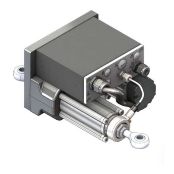
1–2 INTRODUCTION Product overview The GMA-BL Actuator Controller consists of a linear actuator and motor control electronics attached to the actuator. The actuator moves loads in a translational fashion. The rotational movement of the brushless DC motor is reduced by a synchronous belt pulley and gears and then transmitted to a ball screw which transforms the rotational movement into linear movement. - Page 7 1–3 INTRODUCTION Product Overview (continued) An example center guiding application is shown in Figure 1. The sensors (2) sense the edges of the web material (5) and determine the actual position of the web. The GMA-BL Actuator Controller (1) receives this information and guides the pivot carrier (6) of the offset pivot guide (3) by means of the linear actuator so the web material is always in the desired target position.
-
Page 8: Controller Mounting And Actuator Coupling Options
1–4 INTRODUCTION Controller mounting and actuator coupling options Figure 2. Z12 - Rod end coupling connection Top mount style 1 Top mount style 2 Side mount Remote mount Figure 3. A-Clevis coupling connection Top mount style 1 Top mount style 2 Side mount Remote mount Figure 4. - Page 9 1–5 INTRODUCTION Controller mounting and actuator coupling options (continued) Figure 5. KLB - Flange coupling connection Top mount style 1 Top mount style 2 Side mount Remote mount Figure 6. J - Rectangular coupling connections Top mount style 1 Top mount style 2 Side mount Remote mount www.maxcessintl.com...
-
Page 10: Safety Instructions
2–1 SAFETY INSTRUCTIONS Instructions for To ensure safe and problem free installation of the GMA-BL Actuator Controller, the actuator controller must be properly transported and stored, professionally installed, and placed in operation. Proper operation and maintenance will ensure a long service life of the device. -
Page 11: Symbols Used
2–2 SAFETY INSTRUCTIONS Symbols used The following safety identification symbols are used in these operating instructions. WARNING/CAUTION – General danger or important note Reference to general hazards that may result in bodily injuries or damage to device or material. WARNING/CAUTION – Danger due to crushing Reference to danger of injury caused by crushing. -
Page 12: Basic Safety Information
2–3 SAFETY INSTRUCTIONS Basic safety information Proper use The GMA-BL Actuator Controller may be used to provide controlling and guiding functions for Steering and offset pivot guide control ∙ Positioning and slave guidance ∙ Other applications include the control and positioning of Unwind/rewind rolls ∙... - Page 13 2–4 SAFETY INSTRUCTIONS Basic safety information (Continued) Installation and commissioning Any GMA-BL Actuator Controller which is damaged must not be installed or put into service. Only perform installation, maintenance or repair tasks on the GMA-BL Actuator Controller when the machine has been stopped and is secured from being turned on.
- Page 14 2–5 SAFETY INSTRUCTIONS Basic safety information (Continued) Operation WARNING – Danger of injury from crushing. The GMA-BL Actuator Controller contains moving parts which could cause injury due to crushing. Do not touch anything on or in the vicinity of the moving parts. Appropriate protective guards must be installed by the user according to his use of this product.
-
Page 15: Installation
3–1 INSTALLATION Mechanical and electrical installation Use Table 1 to determine the installation drawing you will need for your coupling and mounting style. Table 1. Outline dimension drawings Controller mounting Top mount Actuator coupling Side mount Remote mount Style 1 and Style 2 Z12 Rod End 216650 216655... - Page 16 3–2 INSTALLATION Mechanical and electrical installation (continued) The inductive servo center transducer (ISCT) orientation can be changed on the Z12 Rod End and A Clevis models by loosening two set screws and rotating the ring holding the transducer. The set screws should be tightened to 0.5 Nm (4.4 lb-in).
-
Page 17: Installing The Operator Interface
3–3 INSTALLATION Installing the operator interface Wall mount model Units are in millimeters [inches]. 111 [4.370] M4 x 0.7 (4X) 87.7 [3.453] Operator interface Operator interface shroud Wall Figure 8. Operator interface wall mount kit installation www.maxcessintl.com GMA-BL MI 1-916 1 B... -
Page 18: Panel Mount
3–4 INSTALLATION Installing the operator interface Panel mount model Units are in millimeters [inches]. 124 [4.882] R4 [0.157] MAX (4X) Operator interface Panel Mounting bracket Panel jack screws Installation cutout Figure 9. Operator interface panel mount kit installation www.maxcessintl.com GMA-BL MI 1-916 1 B... -
Page 19: Wiring
3–5 INSTALLATION Wiring Operating voltage range and current rating are listed in Section 6-1, Specifications and shown on the label on the controller housing. All wiring must comply with the essential requirements of the appropriate standard(s) and is the responsibility of the installer. Wiring to the web guiding system must be insulated copper wire with a temperature rating of at least 80⁰C. -
Page 20: Digital Input Matrix Default Configuration
3–6 INSTALLATION Table 2. Digital input matrix default configuration 0 = LOW Note: To ensure that a command is properly executed, all pertinent 1 = HIGH inputs for each command must be switched high or low within - = IGNORE 20 ms of each other and maintained for at least 30 ms. -
Page 21: Digital Output Matrix Default Configuration
3–7 INSTALLATION Table 3. Digital output matrix default configuration 1 = ACTIVE - = IGNORE OUTPUTS* STATUS LOSS OF NULL (AUTOMATIC MODE) CENTERED (SERVO-CENTER MODE) MOTOR BLOCKED POWER OK * Digitial outputs are active low www.maxcessintl.com GMA-BL MI 1-916 1 B... -
Page 22: Maintenance
4–1 MAINTENANCE Maintenance WARNING – Death or injury can result from unexpected movement. Protect against unexpected movement by removing electrical power from the GMA-BL Actuator Controller and the machine into which the GMA-BL Actuator Controller is installed. WARNING – Danger of injury from crushing. Maintenance and repair tasks on the GMA-BL Actuator Controller must be performed only when the machine has been stopped and has been secured from being turned on again. -
Page 23: Replacing The Inductive Servo Center Transducer (Isct)
4–2 MAINTENANCE Replacing the inductive servo center transducer (ISCT) Z12 Rod End and A Clevis models The order number for the ISCT sensor is 573117-021. 1. Install the ISCT sensor into the Z12 or A model. (See Figure 10.) 2. Screw the ISCT sensor into the ISCT holder all the way until it contacts with the actuator rod. -
Page 24: Replacement Parts
4–3 MAINTENANCE Replacement parts Figure 12. Layout of the GMA-BL linear actuator assembly Ball screw Eccentric bolt Thrust tube Timing belt sprocket Driving rod Brushless motor Rod guide ring Timing belt sprocket Ball bearing Synchronous belt Bumper Synchronous belt Spacer tube Rod guide ring Timing belt sprocket Seal... - Page 25 4–4 MAINTENANCE Replacement parts (continued) Table 4. Replacement part list (GR = Gear ratio) Item GR = 1 GR = 2 GR = 3 GR = 4 GR = 5 GR = 6 GR = 8 1, 3, 4 Dependent on stroke, seek advice from service department M159575 M133800 M161621...
-
Page 26: Model Number Key
5–1 MODEL NUMBER KEY Model number key GMA-BL-a-b-ccc-d-e-ISCT-f a = Motor Type 1 = Size 1, 0.28 Nm (39 oz-in), 2100 RPM 2 = Size 2, 0.36 Nm (51 oz-in), 1800 RPM b = Gear Ratio 1 = 1.00 5 = 5.14 2 = 2.25 6 = 6.00 3 = 3.00... -
Page 27: Specifications
6–1 SPECIFICATIONS English units Table 6. GMA-BL Thrust and speed selection table, English units Model Specification Gear Ratio 2.25 5.14 7.71 2.25 5.14 7.71 Max Motor Speed 2100 2100 2100 2100 2100 2100 2100 1800 1800 1800 1800 1800 1800 1800 (rpm) Max Motor Torque... -
Page 28: Metric Units
6–2 SPECIFICATIONS Metric units Table 7. GMA-BL Thrust and speed selection table, Metric units Model Specification Gear Ratio 2.25 5.14 7.71 2.25 5.14 7.71 Max Motor Speed 2100 2100 2100 2100 2100 2100 2100 1800 1800 1800 1800 1800 1800 1800 (rpm) Max Motor Torque... -
Page 29: General
6–3 SPECIFICATIONS General Input voltage range – 24 VDC nominal 18-30 VDC min/max Proper earth grounding is required. Note that the negative supply and housing ground are interconnected. The power supply must have an SELV output, such as Puls CS10.241-S1, or equivalent. -
Page 30: Inputs And Outputs
6–4 SPECIFICATIONS Inputs and outputs Sensor input (2) – Max Input ±20 mA Individually programmable – 0 to 10 mA (Preferred) digital port – Six Digital Inputs, active high Low level: 0 to 0.9 V High level: 3.6 to 24 V –... -
Page 31: Service
To request service or to get replacement parts, contact one of the following addresses: Fife Corporation 222 West Memorial Rd. Oklahoma City, OK, 73114, USA Phone: 1.405.755.1600 Fax: 1.405.755.8425 Web: www.maxcessintl.com Fife-Tidland GmbH Max-Planck-Strasse 8 65779 Kelkheim Deutschland Telefon: +49.6195.7002.0 Fax: +49.6195.7002.933 Web: www.maxcess.eu www.maxcessintl.com GMA-BL MI 1-916 1 B... - Page 32 Tel +86.756.881.9398 Fax +1.405.755.8425 Fax +49.6195.7002.933 Fax +86.756.881.9393 sales@maxcessintl.com sales@maxcess.eu info@maxcessintl.com.cn www.maxcessintl.com www.maxcess.eu www.maxcessintl.com.cn INDIA JAPAN KOREA, TAIWAN, AND SE ASIA Tel +91.22.27602633 Tel +81.43.421.1622 Tel +65.9620.3883 Fax +91.22.27602634 Fax +81.43.421.2895 Fax +65.6235.4818 india@maxcessintl.com japan@maxcessintl.com asia@maxcessintl.com www.maxcess.in www.maxcess.jp © 2013 Maxcess...
Need help?
Do you have a question about the GMA-BL-1-1 and is the answer not in the manual?
Questions and answers