
Related Manuals for Maxcess MAGPOWR CYGNUS-S3 Series


Summary of Contents for Maxcess MAGPOWR CYGNUS-S3 Series
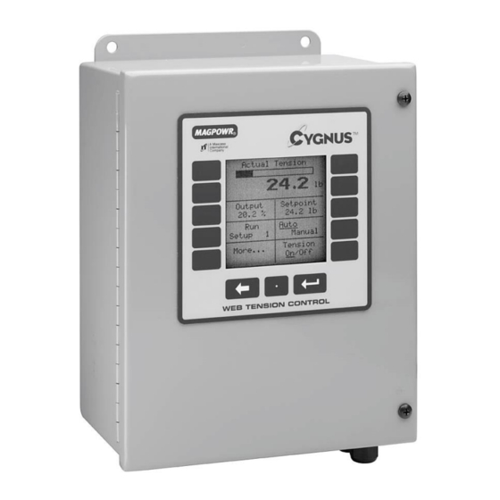
- Page 1 MAGPOWR TENSION CONTROL CYGNUS-S3 Special Readout and Control Instruction Manual CYGNUS-ES3 CYGNUS-DINS3 Digital Tension Readout and Control MI 850A316 1 B...
-
Page 3: Table Of Contents
CONTENTS INTRODUCTION Copyright ......................5 INSTALLATION CYGNUS® basic set-up ..................7 Fuses ....................... 8 ELECTRICAL CONNECTIONS INSTALLATION OF MODEL PS-90 AND PS-24 POWER AMPLIFIERS KEYPAD NAVIGATION SYSTEM SET-UP Hardware configuration ................. 11 6.1.1 Run/stop ................... 11 6.1.2 E-stop ....................11 Software configuration .................. - Page 4 CONTENTS 8.11 Setups ....................... 34 8.11.1 Changing from one set-up to another ..........34 8.11.2 Copy setups ..................34 8.12 Security lock out ..................35 TROUBLESHOOTING Out of round roll comp OFF................39 Out of round roll comp ACTIVE ..............39 Auto-tune diagnostics ..................
-
Page 5: Introduction
Copyright All of the information herein is the exclusive proprietary property of Maxcess International, and is disclosed with the understanding that it will be retained in confidence and will neither be duplicated nor copied in whole or in part nor be used for any purpose other than for which disclosed. -
Page 6: Installation
INTRODUCTION 2.0 Installation Model CYGNUS-E is intended for mounting on any flat vertical surface capable of supporting it. See Figure 9 for dimensions. The CYGNUS-E meets the environmental and mechanical requirements of EN50178. CYGNUS-E exceeds the environmental degree of protection requirement with an IP65 rating. If the IP65 rating is required in the final installation, sealing type cable grips should be used for cable entry. -
Page 7: Cygnus® Basic Set-Up
INSTALLATION CYGNUS® basic set-up This section provides a summary of the basic set-up and calibration of the CYGNUS control. Additional features and options of the CYGNUS control are described later in this manual. NOTE: The CYGNUS-DINS3 is a special version of CYGNUS intended to be used for readout only. The isolated output of TB1 main output terminal has been converted to output a signal proportional to measured tension, and does not provide a corrective signal. -
Page 8: Fuses
INSTALLATION Fuses The only maintenance that may be required on CYGNUS is fuse replacement. Replacement of any fuse requires opening the enclosure, which circumvents the enclosure IP rating. WARNING: DISCONNECT MAINS BEFORE OPENING ENCLOSURE To replace a fuse: On Model CYGNUS-DIN: On Model CYGNUS-E: 1. -
Page 9: Electrical Connections
INSTALLATION 3.0 Electrical connections Figure 3 shows the connections that are required for the basic CYGNUS system. They are: 115 or 230 vac power One or two MAGPOWR load cells Tension reference output to readout device RUN/STOP using the CYGNUS internal logic supply (For readout only – Jumper TB3-1&2) OUTPUT to clutch or brake amplifier, current-to-pressure transducer, motor controller, etc. -
Page 10: Keypad Navigation
KEYPAD NAVIGATION 5.0 Keypad navigation Ten Tactile Feedback “smart” keys that change Home Screen (Digital) functions as you navigate through different screens. Function of each key corresponds to the displayed item next to it. Enter key is used to enter selected numeric data. Back space key clears the last entry. -
Page 11: System Set-Up
SYSTEM SETUP 6.0 System set-up Hardware configuration 6.1.1 Run/stop For tension readout only – jumper terminal TB3.1 to TB3.2. Connect TB3.1 to TB3.2 to initiate the stopping function. During STOP TIME the CYGNUS continues to control tension as a closed loop system but INERTIA COMP and STOP MULTIPLIER are also activated. -
Page 12: I/O Configuration
SYSTEM SETUP 6.2.2 I/O configuration (Home Screen) Select logic type Logic can be active either high or low Select desired input Toggle activates keypad, level requires logic input The CYGNUS has two control outputs. One is Select optional isolated one is sensor type(s) non-isolated. -
Page 13: Remote Tension Set Point/Set-Up Select (Optional)
SYSTEM SETUP 6.2.3 Remote tension set point/set-up select (optional) This option allows both the desired tension and the setup number to be set by an external input. The desired tension input can be either a 0 to 10 VDC analog signal or a remote potentiometer. The analog setup number select input and can be either a 0 to 10 VDC signal or a remote potentiometer. -
Page 14: Load Cell Calibration (Required)
SYSTEM SETUP Load cell calibration (required) 6.3.1 Precision calibration This is the most accurate method of calibration. Use for all applications in which tension accuracy is critical. (Home Screen) Confirm system type Refer to Figure 1 Enter maximum tension. This will scale the analog meter and bar graph. -
Page 15: Weightless Calibration
SYSTEM SETUP 6.3.2 Weightless calibration This is a quick method of calibrating load cells without the need of hanging weights to simulate tension. For tension critical applications use the Precision Calibration method. (NOTE: Repeatability and sensor performance will not be affected) (Home Screen) Confirm system type... -
Page 16: Optional Input Device Calibration
SYSTEM SETUP Optional input device calibration (NOT APPLICABLE FOR READOUT ONLY OPERATION) 6.4.1 Web velocity calibration (Machine must be running) Web velocity input is an option. You only need to calibrate web velocity if you are using a velocity sensor. Configure I/O must be configured to accept the appropriate signal before proceeding. -
Page 17: Rpm Calibration
SYSTEM SETUP 6.4.2 Rpm calibration (Machine must be running) If using an optional RPM sensor you must calibrate the output of the sensor so the CYGNUS can recognize actual RPM. (Home Screen) Press “Home” after calibration is complete Enter current Rewind RPM Actual RPM will be displayed... -
Page 18: Diameter Calibration
SYSTEM SETUP 6.4.3 Diameter calibration (If using Velocity/RPM inputs, you must calibrate them first. See Sections 6.4.1 and 6.4.2) (Home Screen) Displayed if single point is used Enter current diameter. Enter calibration setpoint Displays actual diameter Press to calibrate After calibration. Displays actual sensor signal. -
Page 19: Output Calibration (Optional)
SYSTEM SETUP Output calibration (optional) (Home Screen) Select output to be calibrated and follow screen prompts. www.maxcessintl.com CYGNUS MI 850A316 1 B Page 19 of 66... -
Page 20: Tuning
TUNING 7.0 Tuning (NOT APPLICABLE FOR READOUT ONLY OPERATION) There are three ways to tune your system. The method used depends on your personal preference and end requirements. All tuning must be done with the machine running. In general, the tuning procedures consists of two steps. -
Page 21: Optimize Manual Tuning
TUNING Optimize manual tuning Manual tuning allows the operator to adjust tuning parameters by using one button to stabilize the system and another button to destabilize the system. “Optimizing” allows for precise tuning by first making the system unstable, then re-stabilizing it. NOTE: System must be running to Manually Tune. (Home Screen) Select design method “PI”... -
Page 22: Auto Tuning
TUNING Auto tuning By pressing a single button, the CYGNUS has the unique ability to automatically determine the stable/optimized tuning parameters for most systems. NOTE: Systems with large transients may require manual tuning as outlined in Section 7.2. System must be running in Manual Mode to Auto Tune. (Home Screen) You can choose different design methods without “Auto Tuning”... -
Page 23: Direct Parameter Access Tuning (Optional)
TUNING Direct parameter access tuning (optional) Tuning parameters can easily be directly accessed for re-entry of data. (Home Screen) Enter “I” value Enter “D” value Enter “P” value Enter error limit Direct access to tuning parameters is intended for easy input of previously recorded values generated by Auto Tuning or Manual Optimization. -
Page 24: Optional Functions
OPTIONAL FUNCTIONS 8.0 Optional functions Changing units of measure or language (Home Screen) Select language Select units NOTE: Conversion of existing units is automatically made. No re-calibration is required. Select units www.maxcessintl.com CYGNUS MI 850A316 1 B Page 24 of 66... -
Page 25: Taper Tension (Optional)
OPTIONAL FUNCTIONS Taper tension (optional) (NOT APPLICABLE FOR READOUT ONLY OPERATION) Taper Tension is the reduction of tension as the diameter increases on a rewind. Taper Tension is desired on rewinds to prevent crushed cores and telescoping rolls caused by excess tension build up. Taper can be achieved by either estimating diameter, using the optional diameter input, or calculating diameter based on roll RPM and Velocity inputs (see Section 6.4 to calibrate these devices) (Home Screen) -
Page 26: Inertia / Acceleration Compensation (Optional)
OPTIONAL FUNCTIONS Inertia / acceleration compensation (optional) (NOT APPLICABLE FOR READOUT ONLY OPERATION) This option is used for heavy rolls where the inertia negatively affects stopping and starting and acceleration/deceleration. With this feature the CYGNUS can compensate for the inertia and maintain better control. NOTE: This feature only works with linear ramping of velocity. -
Page 27: Hold Level Control (Optional)
OPTIONAL FUNCTIONS Hold level control (optional) (NOT APPLICABLE FOR READOUT ONLY OPERATION) Hold Level is used to keep tension in the web after a machine is run through a controlled stop and is at rest. This level is adjustable from 0 to 100% of maximum output and should be set just high enough to prevent roll rotation while stopped, but not higher than necessary, since this value may have a momentary effect on tension at start. -
Page 28: Gain Scheduling (Optional)
OPTIONAL FUNCTIONS Gain scheduling (optional) (NOT APPLICABLE FOR READOUT ONLY OPERATION) NOTE: This function requires diameter input and is typically used with large roll builds. It allows one set dynamic tuning parameters at core and a different set at full roll. As the roll changes, diameter the control interpolates all of the parameters to maintain optimized tuning through the entire roll. -
Page 29: Out Of Round Roll Compensation (Optional)
OPTIONAL FUNCTIONS Out of round roll compensation (optional) (NOT APPLICABLE FOR READOUT ONLY OPERATION) CYGNUS has the unique ability to compensate for the Velocity/Tension transients caused by out of round rolls. This feature requires a roll RPM sensor input into TB4.2 and TB4.3. The RPM sensor must be a pulse type which outputs 1 pulse per revolution of the out-of-round roll. -
Page 30: Alarms (Optional)
OPTIONAL FUNCTIONS Alarms (optional) The Alarm Output is used to detect low or high tension and provide indication to an outside device. It is typically used for “Web Break Detection”. (Home Screen) Select Maximum output current Set whether Alarm is used of alarm signal. -
Page 31: Splice Features (Optional)
OPTIONAL FUNCTIONS Splice features (optional) (NOT APPLICABLE FOR READOUT ONLY OPERATION) The CYGNUS contains helpful splice tools that control output during a splice and can reduce the tension transients typically experienced during a splice. Typically input the inverse of the build ratio. -
Page 32: Inverse Diameter Output (Optional)
OPTIONAL FUNCTIONS Inverse diameter output (optional) (NOT APPLICABLE FOR READOUT ONLY OPERATION) The inverse diameter output function is used to slow the motor/drive input RPM to a clutch as a rewind roll builds. This minimizes the slip watts required to be dissipated by the clutch and extends clutch life. This connection is labeled 1/D and is connected between TB4.3 and TB4.4 CYGNUS has two control outputs. -
Page 33: Communication (Optional)
OPTIONAL FUNCTIONS 8.10 Communication (optional) The CYGNUS connects to an Ethernet, DeviceNet or Profibus-DP bus through an optional HMS fieldbus system gateway. The gateway formats the data for the specific field bus. See Figures 2 & 3 for HMS gateway card installation. -
Page 34: Setups
OPTIONAL FUNCTIONS 8.11 Setups The CYGNUS stores up to (10) individual setups for machines that run multiple materials. Individual setups can include different tuning parameters, hold levels and tension set points. Each is independent of the other setup but can be copied if many parameters are similar. 8.11.1 Changing from one set-up to another Select setup (Home Screen) -
Page 35: Security Lock Out
OPTIONAL FUNCTIONS 8.12 Security lock out This function allows you to lock all tuning, calibration and configuration parameters to prevent unauthorized tampering. Operators will still have access to tension set point, tension on/off, auto/manual, manual output and set- up changes. (NOTE: When selecting a security code be sure to record it in the space provided below). (Home Screen) Record Security Code Here: 1. -
Page 36: Troubleshooting
TROUBLESHOOTING 9.0 Troubleshooting Problem Possible Cause Solution or Diagnostic Activating Gain Scheduling caused Gain Scheduling configured See Section 8.5 instability, and deactivating did not incorrectly. cure. Auto tune message: “…if Oscillations in the tension in See Section 7.3 oscillations do not stop within 15 Manual mode are too large cycles.”... - Page 37 TROUBLESHOOTING Problem Possible Cause Solution or Diagnostic Process not running, but When the process is not running the Cygnus is in Auto mode. tension control system is open loop. If the tension is even slightly below Setpoint, the Cygnus will turn full on attempting to correct the tension.
- Page 38 TROUBLESHOOTING Problem Possible Cause Solution or Diagnostic Tension unstable To Quick Stabilize Navigate to Home>>More..>>Program>> Quick Stabilize>> “Press until stable” to immediately try to stabilize. To diagnose Navigate to Home>>More..>>Program>> Quick Stabilize>> Diagnose And follow the directions. Out of Round Roll active and See Section 9.2 may need adjustment www.maxcessintl.com...
-
Page 39: Out Of Round Roll Comp Off
TROUBLESHOOTING Out of round roll comp OFF Message: “Out of Round Roll Compensation has been turned off.” Out of Round Roll Compensation is immediately turned off with the first keystroke of Quick Stabilize. (This does not include minimization of Error Limit.) Continue with Paragraph 9.2. Out of round roll comp ACTIVE Navigate to: Home>>More..>>Program>>Calibrate>>Calibrate Dynamics>>Out of round comp. -
Page 40: Load Cell Diagnostics
TROUBLESHOOTING Load cell diagnostics The CYGNUS features diagnostic tools for load cells. The values displayed in the “Diagnose Load Cell” screens may aid in diagnostics. Refer to Table 1 for possible faults. (Home Screen) Refer to Table 1 for faults www.maxcessintl.com CYGNUS MI 850A316 1 B... -
Page 41: Table 1. Load Cell Diagnostics
TROUBLESHOOTING Table 1. Load cell diagnostics 21 mv Load Cells All voltages without a code that are not in the Normal Range are unspecified faults. Normal Range is 0.00 VDC +/- 0.25 VDC TB6-2 (S+) -5.000 -1.667 -1.000 0.000 1.000 1.667 2.500 5.000... -
Page 42: Gain Scheduling Diagnostics
TROUBLESHOOTING Gain scheduling diagnostics 9.5.1 System is unstable Problem: The system becomes unstable as soon as Gain Scheduling is activated and stays unstable even if Gain Scheduling is then deactivated. Explanation: When Gain Scheduling is activated the PID values are all overwritten by values determined from the Gain Scheduling parameters. -
Page 43: Gain Scheduling Theory
TROUBLESHOOTING Gain scheduling theory Note that a properly calibrated diameter sensor is needed for gain scheduling. When Gain Scheduling is active, stability and tuning are affected by: Overall Gain, Error Limit, Present Diameter, Proportional Gain at Core, Integrator Time at Core, Derivative Time at Core, Core Diameter Proportional Gain at Full Roll,... -
Page 44: Auto Tune And Gain Scheduling
TROUBLESHOOTING Auto tune and gain scheduling Auto tuning with Gain Scheduling usually consists of the following steps: 1. With Run Auto tune at core (or full roll) to generate the Auto Tune Parameters. 2. (Home>>Program>>Calibrate>>Calibrate Dynamics>>Auto Tune Menu) 3. With Gain Scheduling disabled design a control (PID, PI, or I only) using these Auto Tune Parameters. 4. -
Page 45: Screen Definitions, Alphabetical
SCREEN DEFINITIONS 10.0 Screen definitions, alphabetical The descriptions of individual screen functions is provided to aid the understanding of the control operation. Calibration and tuning procedures included in this manual must be used for proper operation. The information contained in this section is not sufficient to allow proper set-up. Screen Function Definition Accel time ___sec... - Page 46 SCREEN DEFINITIONS Screen Function Definition Calibrate setpoint ___RPM Enter a value corresponding to the present speed of the roll being measured by the RPM sensor Calibrate tension meter output Select to calibrate the 0 to 1 mADC auxiliary tension meter output (Not normally required) Calibration single pt/two pt Toggle between single or two point diameter sensor calibration.
- Page 47 SCREEN DEFINITIONS Screen Function Definition Diameter sensor type Toggle to activate diameter sensing capabilities. Select "Voltage" if your diameter sensor provides a 0 to 10 VDC output. Select "Estimated" to allow the CYGNUS to estimate the present diameter based upon the parameters you provide - see also CALIBRATE INERTIA/ ACCEL COMP.
- Page 48 SCREEN DEFINITIONS Screen Function Definition Error lim ___% Enter a value for the error limit between 10% and 100%. The error limit aids the tuning process by setting a boundary for the actual tension error that CYGNUS will recognize during control corrections. Smaller values for the error limit will lengthen the amount of time necessary for CYGNUS to correct large tension transients.
- Page 49 SCREEN DEFINITIONS Screen Function Definition Hold level changes with: tension Toggle to change the HOLD LEVEL output by a scaled amount identical to changes made in the TENSION SETPOINT. This feature accommodates changing hold level requirements for different tension setpoints Hold mult ___ Enter a value to manipulate the control output in HOLD mode when the HOLD LEVEL CHANGES WITH...
- Page 50 SCREEN DEFINITIONS Screen Function Definition Larger roll calibration Select to enter diameter sensor calibration for the larger diameter of a two point calibration Length & velocity units Toggle preferred units for display of diameters, lengths, and speeds Load Cell rating Enter a value corresponding to the total load rating of all load cells present at the sensing roll Load cell type (Magpowr, 500mv, 10v)
- Page 51 SCREEN DEFINITIONS Screen Function Definition Out of round enable Toggle to activate the out of round feature that will compensate for eccentric rolls in an UNWIND application. This feature requires an external RPM sensor Out of round gain ___ Enter a value for the PROPORTIONAL GAIN tuning parameter to be used in the control loop while OUT OF ROUND COMPENSATION is active Out of round max RPM...
- Page 52 SCREEN DEFINITIONS Screen Function Definition Press until stable (decrease error lim) Press either 3 or 8 to decrease the ERROR LIMIT incrementally until the web tension becomes stable. Watch the ACTUAL TENSION display above as you adjust the ERROR LIMIT. Program Select to enter programming screens Prop gain ___...
- Page 53 SCREEN DEFINITIONS Screen Function Definition Setup ___ Displays the number corresponding to the current setup. Selecting this will take you to the setup selection screen; see also CHANGE SETUP and COPY SETUP Single point calibration Select to enter single point diameter sensor calibration Smaller roll calibration Select to enter diameter sensor calibration for the smaller diameter of a two point calibration...
- Page 54 SCREEN DEFINITIONS Screen Function Definition System type Select to enter the system type menu. From here you may select either UNWIND, REWIND, or one of the four point-to-point system configurations. See also Figure 3 Taper Select to enter taper options screen. You may enter the taper percent, full roll, and core diameters.
- Page 55 SCREEN DEFINITIONS Screen Function Definition Tension units Toggle preferred tension measurement units. This will be applied to any displays related to tension measurements Threshold ___% Enter a value for the acceleration threshold. This parameter determines a minimum amount of change in web velocity before the ACCELeration COMPensation feature activates.
- Page 56 SCREEN DEFINITIONS Screen Function Definition Voltage on TB6-2 Display of the voltage present corresponding to the load cell signal input. This is useful for evaluating the performance of load cells by comparing actual vs. expected return signal for a given applied force. Sensor Voltage Display of actual voltage present at the sensor input terminal...
-
Page 57: Figure 1. System Types
FIGURES AND TABLES 1. System types Figure SYSTEM TYPES Figure 1 www.maxcessintl.com CYGNUS MI 850A316 1 B Page 57 of 66... -
Page 58: Figure 2. Fieldbus Card Installation
FIGURES AND TABLES Figure 2. Fieldbus card installation Fieldbus Card Installation COMMKIT-EN, Ethernet COMMKIT-DN, DeviceNet COMMKIT-PB, Profibus Figure 2 www.maxcessintl.com CYGNUS MI 850A316 1 B Page 58 of 66... -
Page 59: Figure 3. Cygnus Wiring Diagram
FIGURES AND TABLES Figure 3. CYGNUS wiring diagram OUTPUT 115/230 VAC 0-10V L2 P.E. MAGPOWR LOAD CELL OPEN FOR RUN OPEN FOR (SEE FIGURE 4 E-STOP FOR DETAIL) FENTON, MO 63026 - USA FENTON, MO 63026 - USA CYGNUS WIRING DIAGRAM Figure 3 www.maxcessintl.com CYGNUS... -
Page 60: Figure 4. Load Cell Wiring Detail
FIGURES AND TABLES Figure 4. Load cell wiring detail Two Magpowr One Magpowr Load Cells Load Cell Two Half Bridge One Half Bridge 500mv Load Cells 500mv Load Cell Precision Bridge Completion Resistors (Contact Load Cell Manufacturer for Values) 10 Volt (DC) Tension Signal LOAD CELL WIRING DETAIL Figure 4... -
Page 61: Figure 5. Wiring Diagram For Use Of Digital Inputs
FIGURES AND TABLES Figure 5. Wiring diagram for use of digital inputs www.maxcessintl.com CYGNUS MI 850A316 1 B Page 61 of 66... -
Page 62: Figure 6. Wiring Diagrams, Remote Tension Setpoint
FIGURES AND TABLES Figure 6. Wiring diagrams, remote tension setpoint Figure 7. Wiring diagrams, remote setup select Table 2. Voltage table, remote setup select +10 vdc (External Power Supply) Power Supply Shield Analog TB4-3, TB4-6, Ground Shield Ground TB5-2 or TB5-4 +5 vdc Desired (Tension... -
Page 63: Figure 8. Cygnus-E Wiring Layout
FIGURES AND TABLES Figure 8. CYGNUS-E wiring layout FENTON, MO 63026 - USA PS90/PS24 REFERENCE FIGURE 3 FOR WIRING CYGNUS-E WITH DOOR OPEN TENSION SENSORS AUXILLARY WIRING POWER CYGNUS-E WITH DOOR CLOSED CYGNUS-E WIRING LAYOUT Figure 8 www.maxcessintl.com CYGNUS MI 850A316 1 B Page 63 of 66... -
Page 64: Figure 9. Outline Dimensions, Cygnus-Din And Cygnus-E
FIGURES AND TABLES Figure 9. Outline dimensions, CYGNUS-DIN and CYGNUS-E 5.67 [144mm] 5.35 [136mm] A Maxcess International Company 5.35 [136mm] 5.67 [144mm] 5.28 [134mm] Recommended Panel Cutout .4 [9.8mm] 3.88 [98.6mm] CYGNUS-DIN 7.0 [178mm] 5.28 6.0 [152mm] [134mm] A Maxcess... -
Page 65: Specifications
SPECIFICATIONS 11.0 Specifications 115 or 230 volts rms, 10%, 24 VA Supply Voltage Supply Frequency: 50 or 60 cycles per second, sinusoidal Fuses: F1, F2 1.6 amp, Littelfuse Part No. 21601.6, or Wickmann Part No. 19194-053-FS Enclosure CYGNUS-DIN Front Panel IP65 (IEC529) Enclosure IP20 (IEC529) -
Page 66: Service
AND AFRICA AND SE ASIA Tel +1.405.755.1600 Tel +86.756.881.9398 Tel +91.22.27602633 Tel +81.43.421.1622 Tel +49.6195.7002.0 asia@maxcessintl.com Fax +1.405.755.8425 Fax +86.756.881.9393 Fax +91.22.27602634 Fax +81.43.421.2895 Fax +49.6195.7002.933 www.maxcess.asia sales@maxcessintl.com info@maxcessintl.com.cn india@maxcessintl.com japan@maxcessintl.com sales@maxcess.eu www.maxcessintl.com www.maxcessintl.com.cn www.maxcess.in www.maxcess.jp www.maxcess.eu © 2018 Maxcess...
Need help?
Do you have a question about the MAGPOWR CYGNUS-S3 Series and is the answer not in the manual?
Questions and answers