
Related Manuals for Maxcess MAGPOWR Spyder-Plus


Summary of Contents for Maxcess MAGPOWR Spyder-Plus
-
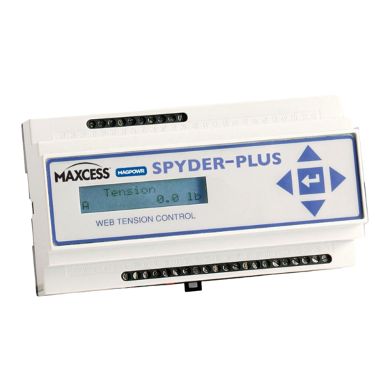
Page 1: Figure 1 Spyder Picture
MAGPOWR TENSION CONTROL MAGPOWR Spyder-Plus Tension Control Instruction Manual Figure 1 Spyder-Plus MI 850A320 1 M... - Page 2 COPYRIGHT All of the information herein is the exclusive proprietary property of Maxcess International, and is disclosed with the understanding that it will be retained in confidence and will neither be duplicated nor copied in whole or in part nor be used for any purpose other than for which disclosed.
- Page 3 9. Basic set-up is complete. Additional features and options are described later in this manual. Always use the RUN/STOP feature to put the Spyder into HOLD mode whenever the machine is stopped to avoid a possible high-tension condition during start-up. www.maxcessintl.com MAGPOWR Spyder-Plus MI 850A320 1 M Page 3 of 60...
- Page 4 RUN/STOP feature to put the Spyder into HOLD mode whenever the machine is stopped to avoid a possible high-tension condition during start-up. For Dancer, Torque use the Hold Level screen to output a value of torque to prevent the dancer arm from moving during Hold. www.maxcessintl.com MAGPOWR Spyder-Plus MI 850A320 1 M Page 4 of 60...
- Page 5 9. Basic set-up is complete. Additional features and options are described later in this manual. Always use the RUN/STOP feature to activate inertia compensation during stopping. See Section 9.6.8. www.maxcessintl.com MAGPOWR Spyder-Plus MI 850A320 1 M Page 5 of 60...
-
Page 6: Table Of Contents
Spyder Web Page 12.4 Update Software via FTP Site 12.5 Spyder Configuration Tool 12.6 Modbus/TCP Communicatioin 12.7 Modbus Parameter List 12.8 Modbus Master Program 13.0 Reset Functions 14.0 Specifications www.maxcessintl.com MAGPOWR Spyder-Plus MI 850A320 1 M Page 6 of 60... -
Page 7: Introduction
Example Edit Value Web Pages 1.0 INTRODUCTION The MAGPOWR Spyder-Plus (hereafter referred to as Spyder) is a microprocessor-based control designed for precise closed loop control of either web tension, dancer position, or open loop tension. The web tension control is capable of controlling web tension in unwind, rewind, or point-to-point applications in any web press. -
Page 8: Installation
58.4 [2.30] 157 [6.18] 35.2 [1.39] 85.8 [3.38] Figure 2 Figure 3 Outline Dimensions Enclosure Top Removal WARNING: DISCONNECT POWER BEFORE OPENING ENCLOSURE www.maxcessintl.com MAGPOWR Spyder-Plus MI 850A320 1 M Page 8 of 60... -
Page 9: Maintenance
DOWN arrow key to scroll through System Type, Output Range, Setpoint Source, Digital Input Active, Numeric Rate, Bar Graph Rate, and Contrast. The UP arrow key usually returns to the previous screen. www.maxcessintl.com MAGPOWR Spyder-Plus MI 850A320 1 M Page 9 of 60... -
Page 10: System Setup
AUTO/MANUAL (Load cell systems and Open Loop Tension systems) Connect Term.12 to Term.11 to switch to Manual mode. During Manual mode, the main output is directly controlled by the Manual setpoint analog input (Term.20). www.maxcessintl.com MAGPOWR Spyder-Plus MI 850A320 1 M Page 10 of 60... -
Page 11: Analog Outputs
The actual Diameter is input as a voltage between Term.38 and Term.39. The input can take a voltage proportional to diameter up to 10 VDC. An input voltage of 0 volts is equal to a diameter of 0. See Section 8.3 for calibrating diameter. www.maxcessintl.com MAGPOWR Spyder-Plus MI 850A320 1 M Page 11 of 60... -
Page 12: 6.0 Tension Control
CORE TENSION (With taper tension) Display only. This is the setpoint at core diameter only. At other diameters the setpoint is less than the core setpoint if Taper Percent > 0. www.maxcessintl.com MAGPOWR Spyder-Plus MI 850A320 1 M Page 12 of 60... -
Page 13: Figure 5 Basic Load Cell System Connections
The lower left character displays the status of the Spyder. See Section 6.2.1.1 for description of the status character. Figure 5. Basic Load Cell System Connections www.maxcessintl.com MAGPOWR Spyder-Plus MI 850A320 1 M Page 13 of 60... -
Page 14: Figure 6 Load Cell System Types
+10 VDC output ranges. See Section 9.4 for recalibrating the output when using the 4-20 mADC range. See Figure 4 for jumper settings. Figure 6 Load Cell System Types www.maxcessintl.com MAGPOWR Spyder-Plus MI 850A320 1 M Page 14 of 60... - Page 15 This parameter controls the filtering for the bar graph actual tension and the actual output displays. Default values work well in most applications. 6.2.2.9 SCREEN CONTRAST Adjusts the screen contrast. See Section 10.1, General Problems, when screen shows no characters. www.maxcessintl.com MAGPOWR Spyder-Plus MI 850A320 1 M Page 15 of 60...
-
Page 16: Load Cell Calibration
By doing so the system is tuned to be as responsive as possible and still remain stable throughout its range of operation. See Section 6.4.2. www.maxcessintl.com MAGPOWR Spyder-Plus MI 850A320 1 M Page 16 of 60... -
Page 17: Quick Stabilize
Navigate to the Tuning menu and press . For point to point systems this yields the screen: The Spyder should be optimized in the order shown. See Section 6.4.3 for a typical tuning screen. www.maxcessintl.com MAGPOWR Spyder-Plus MI 850A320 1 M Page 17 of 60... -
Page 18: Load Cell Connections
Basic setup of the load cell control system is now complete. See Section 9.0 for optional settings. Load Cell Connections Figure 8. Load Cell Connections for One or Two Load Cells www.maxcessintl.com MAGPOWR Spyder-Plus MI 850A320 1 M Page 18 of 60... -
Page 19: Load Cell System Complete Wiring
TENSION SETPOINT CLOSE FOR MANUAL (1K TO 10K) CLOSE FOR TENSION OFF Figure 9. Complete Load Cell System Wiring Load Cell Control Diagram Figure 10. Load Cell Control Diagram www.maxcessintl.com MAGPOWR Spyder-Plus MI 850A320 1 M Page 19 of 60... -
Page 20: 7.0 Dancer Control
24 VDC power input is Earth ground referenced. See Figure 12 and Section 7.3 for connecting the DFP or DFP-2 (Dancer Follower Potentiometers) according to the Dancer system types. Figure 11. Basic Dancer Wiring www.maxcessintl.com MAGPOWR Spyder-Plus MI 850A320 1 M Page 20 of 60... -
Page 21: Software Configuration
0 to 100%. The lower left character displays the status of the Spyder. E = E-Stop H = Hold = Start A = Automatic (Run) S = Stop OFF = Tension OFF 7.2.1.2 SETPOINT POSITION www.maxcessintl.com MAGPOWR Spyder-Plus MI 850A320 1 M Page 21 of 60... - Page 22 This value may be changed either at the keypad, the web page or by Modbus/TCP. Use the “Setpoint Position” screen in the “Operator Loop” to change the software setpoint. www.maxcessintl.com MAGPOWR Spyder-Plus MI 850A320 1 M Page 22 of 60...
-
Page 23: Dancer Input Setup
Both are calibrated in the same way. Press either the or key to begin a calibration. www.maxcessintl.com MAGPOWR Spyder-Plus MI 850A320 1 M Page 23 of 60... - Page 24 DOWN arrow keys are used to change dancer position instead. For this reason, the web must be stopped (Run/Stop = Stop) and restarted (Run/Stop = Run) to leave the tuning screens. A screen is provided to warn the www.maxcessintl.com MAGPOWR Spyder-Plus MI 850A320 1 M Page 24 of 60...
-
Page 25: Tuning
The position setpoint input is not active during tuning. The Spyder automatically steps through several separate stages in an attempt to stabilize the process. The Quick Stab screens are all similar to this one: www.maxcessintl.com MAGPOWR Spyder-Plus MI 850A320 1 M Page 25 of 60... -
Page 26: Optimize Tuning
The Spyder should be optimized at core (PI tuning) only after it has been optimized at full roll. On unwinds “Quick Stab” may be needed to keep the system stable while an initial roll is unwound. See 7.5.2.3 for a typical tuning screen. www.maxcessintl.com MAGPOWR Spyder-Plus MI 850A320 1 M Page 26 of 60... -
Page 27: Dancer, Torque Control Diagram
Ethernet or by the UP and DOWN arrow keys. The dancer does not need to be stopped to exit the Tuning screens. Dancer, Torque Control Diagram Figure 13. Dancer, Torque Control Diagram www.maxcessintl.com MAGPOWR Spyder-Plus MI 850A320 1 M Page 27 of 60... -
Page 28: Dancer, Speed Control Diagram
7.0 DANCER CONTROL Dancer, Speed Control Diagram Figure 14. Dancer, Speed Control Diagram Dancer System Complete Wiring Figure 15. Complete Dancer System Wiring www.maxcessintl.com MAGPOWR Spyder-Plus MI 850A320 1 M Page 28 of 60... -
Page 29: Open Loop Tension Control Based On Diameter
CORE TENSION (With taper tension) Display only. This is the setpoint at core diameter only. At other diameters the setpoint is less than the core setpoint if Taper Percent > 0. www.maxcessintl.com MAGPOWR Spyder-Plus MI 850A320 1 M Page 29 of 60... -
Page 30: Figure 16 Complete Open Loop Tension System Wiring
The lower left character displays the status of the Spyder. See Section 8.2.1.1 for description of the status character. Figure 16. Complete Open Loop Tension System Wiring www.maxcessintl.com MAGPOWR Spyder-Plus MI 850A320 1 M Page 30 of 60... - Page 31 This parameter controls the filtering for the bar graph actual tension and the actual output displays. Default values work well in most applications. 8.2.2.11 SCREEN CONTRAST This screen allows adjustment of the screen contrast. See Section 10.1, General Problems, when screen shows no characters. www.maxcessintl.com MAGPOWR Spyder-Plus MI 850A320 1 M Page 31 of 60...
-
Page 32: Diameter Calibration
Basic setup of the open loop tension system is now complete. See Section 9.0 for optional settings. 8.5 Open Loop Tension Control Diagram Figure 17. Open Loop Tension Control Diagram www.maxcessintl.com MAGPOWR Spyder-Plus MI 850A320 1 M Page 32 of 60... -
Page 33: Optional Functions
Taper Percent, Section 6.2.1.3 must be set to "0" to calibrate taper. Enter the present diameter. This should be the present diameter of the roll. The Spyder must be in Run mode. Press to finish the calibration. www.maxcessintl.com MAGPOWR Spyder-Plus MI 850A320 1 M Page 33 of 60... -
Page 34: Calibrate Inputs Menu (Load Cell And Open Loop Tension Control)
Cells Enabled and Open Loop Tension systems) Use the LEFT and RIGHT arrow keys to adjust the meter output on Term.33 and Term.34 to 1 mADC or 10 VDC. Press when finished. www.maxcessintl.com MAGPOWR Spyder-Plus MI 850A320 1 M Page 34 of 60... -
Page 35: Security Menu
Enter a value based upon the amount of time it takes your machine to ramp down from steady state operation to a complete stop. When this time has expired, Spyder will automatically proceed into HOLD mode. www.maxcessintl.com MAGPOWR Spyder-Plus MI 850A320 1 M Page 35 of 60... - Page 36 The core offset tension is too high at core use a negative value for core offset. If tension is too low at core use a positive value for core offset. The range of this parameter is from -20% to 100%. The default is 0%. www.maxcessintl.com MAGPOWR Spyder-Plus MI 850A320 1 M Page 36 of 60...
-
Page 37: Troubleshooting
Spyder is in Auto mode. tension/position control system is open loop. If the tension/position is even slightly above Setpoint, the Spyder will turn full off attempting to correct the tension/position. www.maxcessintl.com MAGPOWR Spyder-Plus MI 850A320 1 M Page 37 of 60... -
Page 38: Tuning Problems (Load Cell Control)
The system is less stable When the message appears retune P at the core” repeatedly appears at some intermediate roll present diameter rather than at core. diameter than it is at core. www.maxcessintl.com MAGPOWR Spyder-Plus MI 850A320 1 M Page 38 of 60... -
Page 39: Tuning Problems (Dancer Control)
Adjust the position setpoint until the desired dancer position is achieved. Use PID (torque) or PI (speed). These can be selected on the Configure menu following selection of the Control Type. www.maxcessintl.com MAGPOWR Spyder-Plus MI 850A320 1 M Page 39 of 60... -
Page 40: Load Cell Calibration Problems
There may be a short between Term.23 and Term.24. This message also appears if the calibration load was never applied to the sensing roll. www.maxcessintl.com MAGPOWR Spyder-Plus MI 850A320 1 M Page 40 of 60... -
Page 41: Load Cell Diagnostic Voltages
TERM.26 (P-) to TERM.24 (S-) leg open (TERM.25 (P+) and TERM.23 (S+) reversed) or (TERM.26 (P-) and TERM.24 (S-) reversed) (TERM.25 (P+) and TERM.24 (S-) reversed) or (TERM.26 (P-) and TERM.23 (S+) reversed) www.maxcessintl.com MAGPOWR Spyder-Plus MI 850A320 1 M Page 41 of 60... -
Page 42: Alphabetical List Of Screen Definitions
From Taper Setup menu. When is pressed on the Present Dia screen, the operator is asked if taper should be calibrated. If “Yes” is selected the present diameter is entered next. www.maxcessintl.com MAGPOWR Spyder-Plus MI 850A320 1 M Page 42 of 60... - Page 43 Derivative Time From the Parameters menu Set the derivative time. Derivative time is only used for Control Type “Dancer, Torque”. The factory default is 1.25 sec. www.maxcessintl.com MAGPOWR Spyder-Plus MI 850A320 1 M Page 43 of 60...
- Page 44 Two different screens look like this one. They are used to optimize the given parameter by first pressing until the system becomes slightly unstable and then press to stabilize. See Section 6.4.2 or 7.5.2, Tuning. (Tuning) www.maxcessintl.com MAGPOWR Spyder-Plus MI 850A320 1 M Page 44 of 60...
- Page 45 This setting also determines the scale for the analog displays. www.maxcessintl.com MAGPOWR Spyder-Plus MI 850A320 1 M Page 45 of 60...
- Page 46 Displays the estimated diameter if diameter has been calibrated. In Cal Diameter menu for Open loop tension system. Used to calibrate the diameter. Diameter calibration is required. www.maxcessintl.com MAGPOWR Spyder-Plus MI 850A320 1 M Page 46 of 60...
- Page 47 This screen announces that Proportional Gain has been increased to the maximum allowed during tuning (50). Proportional Gain can be set higher than this using the Parameters menu, but that is not recommended. www.maxcessintl.com MAGPOWR Spyder-Plus MI 850A320 1 M Page 47 of 60...
- Page 48 Enter a value based upon the amount of time it takes your machine to ramp up from stopped to steady state operation. If the tension spikes during this time, try increasing this START TIME value. www.maxcessintl.com MAGPOWR Spyder-Plus MI 850A320 1 M Page 48 of 60...
- Page 49 Max Tension Tune I First. Then P second From the Tuning menu for point to point systems. The Spyder should be optimized in the order shown. www.maxcessintl.com MAGPOWR Spyder-Plus MI 850A320 1 M Page 49 of 60...
- Page 50 Dancer system. Use Taper? From the Taper Setup menu for Load Cell control or the Configure menu for Open Loop Tension control. Select "Yes" to enable taper tension. www.maxcessintl.com MAGPOWR Spyder-Plus MI 850A320 1 M Page 50 of 60...
-
Page 51: Communication
Parameter values which are editable will be shown with a standard web page link. Parameters which are not editable will not have a link. Example: http://192.168.1.100 www.maxcessintl.com MAGPOWR Spyder-Plus MI 850A320 1 M Page 51 of 60... -
Page 52: Figure 18 Spyder Status Web Page
To change the value of a parameter, click on the link for the data value. The Spyder will return a page with an input box to allow entering a new value. When the new value has been entered click on the "Submit" button. Examples: Figure 20. Example Edit Value Web Pages www.maxcessintl.com MAGPOWR Spyder-Plus MI 850A320 1 M Page 52 of 60... -
Page 53: Update Software Via Ftp Site
For downloading Spyder software from a local FTP server running on a local PC you can get the SpyderWare installation kit from the Maxcess website. This kit will install an FTP server on a Windows PC which can be used to download software to the Spyder. -
Page 54: Modbus Parameter List
Taper Percent FLOAT Data LC, OPT Read / { 0.0 - 100.0 } % Write 0x43 Is Taper Setup BYTE Read / 0 = No Write 1 = Yes www.maxcessintl.com MAGPOWR Spyder-Plus MI 850A320 1 M Page 54 of 60... - Page 55 FLOAT LC, DT, DS, Read / { 0 - 511 } Write 0x6E Tension Setpoint 0% Calibration Point FLOAT LC, OPT Read / { 0 - 4095 } Write www.maxcessintl.com MAGPOWR Spyder-Plus MI 850A320 1 M Page 55 of 60...
- Page 56 1 = Tension On 0x95 Tension Setpoint FLOAT None Read { 0.0 - 99999.0 } lb. Only 0x97 Actual Tension FLOAT None LC, OPT Read { 0.0 - 99999.0 } lb. Only www.maxcessintl.com MAGPOWR Spyder-Plus MI 850A320 1 M Page 56 of 60...
-
Page 57: Modbus Master Program
IP address of the Spyder, update rate and Spyder Program Number. The Spyder program number is displayed on the Spyder for a few seconds after applying power. www.maxcessintl.com MAGPOWR Spyder-Plus MI 850A320 1 M Page 57 of 60... -
Page 58: Reset Functions
To download new software hold down the "Up" and "Down" arrow keys while turning on power and hold the keys until the display shows "Update Software". See Section 12.4 for software updating. www.maxcessintl.com MAGPOWR Spyder-Plus MI 850A320 1 M Page 58 of 60... -
Page 59: Specifications
-10 to +10 VDC, 1 mADC maximum Tension meter or 0 to 1 mADC or 0 to +10 VDC analog Inverse Diameter output Communications: Ethernet TCP/IP Web server interface FTP Client Modbus/TCP Slave www.maxcessintl.com MAGPOWR Spyder-Plus MI 850A320 1 M Page 59 of 60... - Page 60 AND AFRICA AND SE ASIA Tel +1.405.755.1600 Tel +86.756.881.9398 Tel +91.22.27602633 Tel +81.43.421.1622 Tel +49.6195.7002.0 asia@maxcessintl.com Fax +1.405.755.8425 Fax +86.756.881.9393 Fax +91.22.27602634 Fax +81.43.421.2895 Fax +49.6195.7002.933 www.maxcess.asia sales@maxcessintl.com info@maxcessintl.com.cn india@maxcessintl.com japan@maxcessintl.com sales@maxcess.eu www.maxcessintl.com www.maxcessintl.com.cn www.maxcess.in www.maxcess.jp www.maxcess.eu © 2015 Maxcess...
Need help?
Do you have a question about the MAGPOWR Spyder-Plus and is the answer not in the manual?
Questions and answers