Table of Contents
Advertisement
Quick Links
Fife Corporation
P.O. Box 26508, Oklahoma City, OK 73126, USA
Phone: 405.755.1600 / Fax: 405.755.8425
www.fife.com / E-mail: fife@fife.com
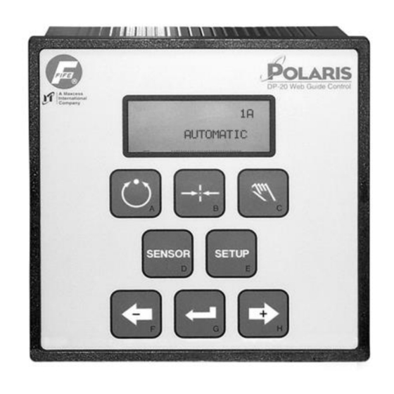
POLARIS DP-20
WEB GUIDE CONTROLLER
Additional User Manual Instructions
Setup For Hardlock And Stroke Limits With DP-20
1A
AUTOMATIC
×
-ãããããÜÜÜÜÜ+
05-14-2004
DP-20 WEB GUIDE CONTROLLER
Figure Sheet 1-875
Advertisement
Table of Contents

Related Manuals for Maxcess FIFE POLARIS DP-20


Summary of Contents for Maxcess FIFE POLARIS DP-20
- Page 1 Fife Corporation P.O. Box 26508, Oklahoma City, OK 73126, USA Phone: 405.755.1600 / Fax: 405.755.8425 www.fife.com / E-mail: fife@fife.com POLARIS DP-20 WEB GUIDE CONTROLLER Additional User Manual Instructions Setup For Hardlock And Stroke Limits With DP-20 AUTOMATIC × -ãããããÜÜÜÜÜ+ 05-14-2004 DP-20 WEB GUIDE CONTROLLER Figure Sheet 1-875...
- Page 2 05-14-2004 DP-20 WEB GUIDE CONTROLLER Figure Sheet 1-875...
- Page 3 DP-20 WEB GUIDE CONTROLLER ADDITIONAL USER MANUAL INSTRUCTIONS COPYRIGHT COPYRIGHT All rights reserved. Any reproduction of this User Manual, in any form, in whole or in part, requires the prior written consent of Fife Corporation. The information given in this User Manual is subject to change without notice. We have compiled this User Manual with the greatest possible care and attention;...
- Page 4 05-14-2004 DP-20 WEB GUIDE CONTROLLER Figure Sheet 1-875...
-
Page 5: Table Of Contents
DP-20 WEB GUIDE CONTROLLER ADDITIONAL USER MANUAL INSTRUCTIONS TABLE OF CONTENTS GENERAL INFORMATION Explaination of Additional Features ................1-1 SYSTEM SETUP Setup Procedures for Servo Center, Hardlock, and Stroke Limits ....... 2-1 3X.1.4, Calibration, Servo-Center Sensor.............. 2-1 3X.1.7, Servo-Center Polarity ................2-2 3X.5.4, Hardlock Control.................. - Page 6 05-14-2004 DP-20 WEB GUIDE CONTROLLER Figure Sheet 1-875...
-
Page 7: General Information
DP-20 WEB GUIDE CONTROLLER ADDITIONAL USER MANUAL INSTRUCTIONS GENERAL INFORMATION NOTE: The information in this document supplements or supersedes that which is listed in the Polaris DP-20 Web Guide Controller User Manual, Figure Sheet 1-862. Explaination of Additional Features GUIDE POSITION FEEDBACK The guide position feedback is provided by the customer supplied 10K potentiometer (with a 1.91K resistor in series). - Page 8 05-14-2004 DP-20 WEB GUIDE CONTROLLER Figure Sheet 1-875...
-
Page 9: System Setup
DP-20 WEB GUIDE CONTROLLER ADDITIONAL USER MANUAL INSTRUCTIONS SYSTEM SETUP Setup Procedures for Servo Center, Hardlock, and Stroke Limits When setting up the system, both Hardlock and Stroke Limits must be turned OFF. To verify that they are turned off, use the “3X.5.4, Hardlock Control” procedure and the “3X.5.5, Stroke Limits”... -
Page 10: 1.7, Servo-Center Polarity
DP-20 WEB GUIDE CONTROLLER ADDITIONAL USER MANUAL INSTRUCTIONS 8. Press the ENTER key. COVER SENSOR will ~ƒ 3F.1.4.3 be displayed on line 2. COVER SENSOR -ãããããããããá+ 95% 9. Use the ARROW keys to move the guide to the ~ƒ 3F.1.4.3 COVER SENSOR opposite mechanical stop. -
Page 11: 5.4, Hardlock Control
DP-20 WEB GUIDE CONTROLLER ADDITIONAL USER MANUAL INSTRUCTIONS 7. Use the ARROW keys to adjust the Servo- × 3A.1.7.1 Center Polarity to the opposite setting, as SETUP (MAN) ~ƒ POLARITY indicated on line 4. 8. Press the ENTER key to store the change. The system will exit the setup menus, and MANUAL ×... -
Page 12: 5.6, Set Stroke Limits
DP-20 WEB GUIDE CONTROLLER ADDITIONAL USER MANUAL INSTRUCTIONS 3X.5.6, Set Stroke Limits This procedure is used to set the Stroke Limits. If the Stroke Limits are set to ON in the Stroke Limits menu, these limits are active in all modes. 1. -
Page 13: 5.5, Stroke Limits
DP-20 WEB GUIDE CONTROLLER ADDITIONAL USER MANUAL INSTRUCTIONS 9. Press the ENTER key to store the new MANUAL STROKE LIMITS, or press the MANUAL key × -ãããããáÜÜÜÜ+ to abort the changes. The system will exit the setup menus, and return to the Operator Level. -
Page 14: Features Of The Lcd Panel
DP-20 WEB GUIDE CONTROLLER ADDITIONAL USER MANUAL INSTRUCTIONS Features of the LCD Panel LINE 4 While at the Operator Level, in Automatic mode, Servo AUTOMATIC Center mode, or Manual mode, if Stroke Limits are set to ON, this × -ãããããáÜÜÜÜ+ line flashes STROKE LIMIT if either one of the programmed stroke STROKE LIMIT limits is reached.
Need help?
Do you have a question about the FIFE POLARIS DP-20 and is the answer not in the manual?
Questions and answers