
Related Manuals for Maxcess H6630EM


Summary of Contents for Maxcess H6630EM
- Page 1 H6630EM Electro-Mechanical Controller User Manual Engineered Guiding Solutions H6630EM...
- Page 3 H6630EM Electro-Mechanical Controller Copyright 2016 Fife Corporation 222 W. Memorial Road Oklahoma City, Ok 73114 USA 1+405-755-1600...
- Page 4 Manual Rev ISION ISTORY Manual Software Date Comments Revision Revision 1.00 0.00 11-20-2014 Initial Release 2.00 0.00 04-13-2016 Brand Edits Note: While reasonable efforts have been taken in the preparation of this manual to assure its accuracy, Fife Corporation does not assume responsibility for errors or omissions; nor is any liability assumed for damages resulting from use of this information.
-
Page 5: Table Of Contents
Table of Contents Table of Contents Section 1 – Introduction ......................... 1 H6630EM Product History ......................1 Overview ..........................1 Specifications ........................... 2 Part Nomenclature ........................3 Digital and Analog IO ....................... 3 Accessory Cables ........................4 Accessory Actuators – H5535 Series ..................4 Section 2 –... - Page 6 Communications Module ......................30 Changing, Verifying, or Setting up an H6630 Controller IP Address ..........30 Ethernet Module LED Indicators ....................31 Troubleshooting the Ethernet Module ....................32 Section 6 – Repair/Replacement ......................33 Controller Drive Unit .......................33 Operator Interface – HMI ......................33 Rev. 2.0 04/16 H6630EM-LIT...
- Page 7 Battery Life/Replacement ......................49 Controller ........................... 49 HMI (Human Machine Interface) ....................49 Appendix B ............................51 Error Codes / Trip Codes ......................51 H25-4674 – H6630 Advanced Parameters Trip Indications ............52 Index ..............................63 H6630EM-LIT Rev. 1.0 11/14...
- Page 8 Table of Contents Rev. 2.0 04/16 H6630EM-LIT...
-
Page 9: Section 1 - Introduction
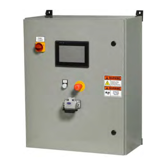
The controller is powered by 460-380Vac, 3 phase, 48/65Hz and requires a 15 amp service. Optional 230-200Vac service is available. The H6630EM controller has a color touchscreen operator interface (described as the HMI or Human Machine Interface). The HMI replaces traditional pushbuttons and includes screens specific for operation, maintenance, setup and diagnostics. -
Page 10: Specifications
Enclosure: NEMA 4, ANSI #61 Gray Protection Class: NEMA 4, IP54 Protection Devices: Fused Disconnect, Stop, and Lock-Out Tag-Out (LOTO) switch Dimensions: 24” wide x 30” high x 12” deep, (610 x 762 x 305 mm) Weight: 110 lbs. (50kg) Rev. 2.0 04/16 H6630EM-LIT... -
Page 11: Part Nomenclature
(2) Standard analog inputs, 10 bit + sign (configurable voltage or current) 2 Analog Outputs • (2) ±10Vdc, 0-20mA, (configurable voltage or current) 10 bit 6 Digital Input/Outputs • (3) Bi-directional Input/Outputs • (3) Dedicated Inputs H6630EM-LIT Rev. 1.0 11/14... -
Page 12: Accessory Cables
Section 1 - Introduction 1-6 Accessory Cables • Absolute Encoder Cable H5535-FDBK-20M feedback cable • Motor Cable (standard) H5535-PWR-20M power cable • Motor Cable for motors with brakes H5535-PWRBRK-20M power cable 1-7 Accessory Actuators – H5535 Series Rev. 2.0 04/16 H6630EM-LIT... -
Page 13: Section 2 - Installation
Section 2 – Installation 2-1 Mounting Mount the new H6630EM control panel in a convenient location for operation of the control screen. Place the controller close enough to terminate the H5535-FDBK-20M (encoder cable) and H5535- PWR-20M (motor cable) or H5535-PWRBRK-20M (motor cable with brake) to reach the control panel. -
Page 14: Control Wiring
Refer to the specific H4803 series drawing supplied with the system or to the appendix in this H6630EM manual. If a customer LRR is not used, do not remove the jumper in the control panel. -
Page 15: Connecting Power Wiring
H6630EM manual. Terminate ensuring each device has good electrical and mechanical connection at the termination point. - Page 16 Section 2 - Installation Rev. 2.0 04/16 H6630EM-LIT...
-
Page 17: Section 3 - Hmi (Human Machine Interface) Screens
Section 3 – HMI (Human Machine Interface) Screens Each H6630EM system is provides with a 7 inch touch screen HMI for local operation and setup. System operation is selectable with three modes of operation i.e. Auto, Manual, and Roll Center/Park modes. - Page 18 Log Out - out within a few minutes, log out will be performed automatically by the system. Enables or disables (toggle) drive from powering the motor. Drive Enable - When disabled, no holding torque is applied. Rev. 2.0 04/16 H6630EM-LIT...
- Page 19 “Enter Actuator Position”. See Position - above. < Offset > Momentary button which increments or decrements the counts of offset. See “Offset Increment” button. Offset Clear - Momentary button which clears any incremented offset. H6630EM-LIT Rev. 1.0 11/14...
-
Page 20: Main Screen Status
Otherwise, they can only be viewed. When any alarms have occurred and have not been acknowledged, the message “Acknowledge Alarms” will flash on the main screen. Rev. 2.0 04/16 H6630EM-LIT... -
Page 21: Maintenance Screen
Neg SW Limit - Note: The “Accept SW Limit” button must be used to save the value. Momentary button which saves the positive and negative Accept SW Limits - software limits to the controller after changes have been made. H6630EM-LIT Rev. 1.0 11/14... - Page 22 Momentary button which saves and displays the entered position of Calibrate - the actuator. Enable/Disable Drive - Same as “Drive Enable” on the main screen. Allows setting of the Motor RPM when the Roll Center/Park mode is Park RPM - used. Rev. 2.0 04/16 H6630EM-LIT...
- Page 23 Adjustable value which allows offset to increment at a desired distance when using the Offset buttons. Placing a Offset Increment - negative sign in front of the value will switch the direction the buttons increment or decrement the guide point. H6630EM-LIT Rev. 1.0 11/14...
-
Page 24: Maintenance Screen Status
Detector Zero Value is the value captured when the “Detector Zero” button is pressed. Detector Error is different between current strip position and Detector Zero Value. Percent Load is a real time display as a % of the current load on the actuator motor. Use this when setting “Load Limit”. Rev. 2.0 04/16 H6630EM-LIT... -
Page 25: Communication Screen
The HMI and drive communicate to each other via Ethernet. Follow the instructions on this screen if you need to make changes to the system IP address. From this screen, users are able to access the password change screen and the Alarm/Trends screen. H6630EM-LIT Rev. 1.0 11/14... -
Page 26: Alarms/Trends Configuration Screen
HMI memory to an external USB connected device, including the current day trend file. Files are transferred in .CSV file format. Transfer Guide Position Trend to USB: Same as “Motor Current Trend Files” above. Rev. 2.0 04/16 H6630EM-LIT... -
Page 27: Trends Screen
Each window represents the last two hours of data. Touching a particular window will expand that trend to full screen. Note: These trends are only active in automatic mode. H6630EM-LIT Rev. 1.0 11/14... - Page 28 Section 3 – HMI (Human Machine Interface) Displays Rev. 2.0 04/16 H6630EM-LIT...
-
Page 29: Section 4 - Operation/Configuration/Calibration
Software Limit Setting may be adjusted to an expanded range temporarily per the next section to allow the unit to reach the center position. H6630EM-LIT Rev. 1.0 11/14... -
Page 30: Actuator Software Limit Setting (Range Of Travel)
Once the strip is placed at the desired position to be guided to, the “Detector Zero” button can be pressed to capture the desired control point. Rev. 2.0 04/16 H6630EM-LIT... -
Page 31: Post Calibration Steps
While in “closed loop” operation, i.e., line in operation, adjust the “Auto Gain” to provide proper control. If the Gain is set too high, the system will be unstable and oscillate. If it is set too CAUTION low, the response will be sluggish for most applications. H6630EM-LIT Rev. 1.0 11/14... - Page 32 Section 4 – Operation/Configuration/Calibration Rev. 2.0 04/16 H6630EM-LIT...
-
Page 33: Section 5 - Troubleshooting
Programming buttons – allows scroll up/down or selecting specified digit of a value. Mode Button – once depressed allows changing of a value at the lower display, press again to exit. Reset (red button) – performs a drive reset and cycles the program. H6630EM-LIT Rev. 1.0 11/14... -
Page 34: Keypad Navigation Example
16.10-13 Drive IP Address 16.14-17 Drive Subnet Mask 16.32 Reinitializes Ethernet communications 16.37 Turns on Ethernet communications. Maintenance Screens The HMI has individual maintenance screens which provide additional or alternate indications of device output readings or comp nent status. Rev. 2.0 04/16 H6630EM-LIT... -
Page 35: Electrical Checks
2. Reduce the value by 25%. Operate and see if the tripping is eliminated. If not, try reducing by another 25%. 3. Perform a “1001” save to retain the value. If the condition is still reoccurring, a motor auto tune may need to be performed (See “Motor Auto Tune”). H6630EM-LIT Rev. 1.0 11/14... -
Page 36: Over Speed Trip - O.spd
Set parameter #17.13, set to “OFF” and do a “1001” save. c. Set parameter #00.40 to 2 (this selects a low speed test which rotates the motor two rotations). d. Pull the connector with terminal points 21 through 31 from the front of the drive. Rev. 2.0 04/16 H6630EM-LIT... -
Page 37: Encoder Visual Trip Indications
The actuator motors and positioner motors all have absolute encoders. All programs are set up with the necessary encoder configuration parameters which perform an auto configuration upon power up. If encoder issues are apparent, check encoder cabling and terminations. Power down the unit and re-energize to reset. H6630EM-LIT Rev. 1.0 11/14... -
Page 38: Communications Module
IP address W 16.10 IP address X 16.11 16.12 IP address Y 16.13 IP address Z 16.14 Subnet mask W 16.15 Subnet mask X Subnet mask Y 16.16 Subnet mask Z 16.17 Figure 7 Controller Ethernet Module Rev. 2.0 04/16 H6630EM-LIT... -
Page 39: Ethernet Module Led Indicators
Remember to do a “1001” save, if changing the Ethernet address of the controller. Refer to the “Keypad Navigation” example to do a “1001” save. Refer to Section 3-3 for an example of the “Communications” screen. H6630EM-LIT Rev. 1.0 11/14... -
Page 40: Troubleshooting The Ethernet Module
Power OFF the drive and remove the module. Visually inspect the connection to the controller, clean if required, and reseat. If the fault reappears, try a replacement module. Rev. 2.0 04/16 H6630EM-LIT... -
Page 41: Section 6 - Repair/Replacement
Fife Corporation on a USB flash drive, along with the Winflash software and files. IS-1293 “Instructions for using H6630 Download Tool to download program files to the H6630EM controller using Ethernet”; can be found in Appendix A of this manual. 6-2 Operator Interface – HMI In the event that the HMI must be replaced due to failure, refer to Installation Instructions (IS- 1287). - Page 42 Section 6 – Repair/Replacement Rev. 2.0 04/16 H6630EM-LIT...
-
Page 43: Typical Connections For Incoming Power
Appendix A Appendix A Typical Connections for Incoming power See specific wiring schematic for application, supplied with equipment when received. H6630EM-LIT Rev. 1.0 11/14... -
Page 44: Typical Connections For Network Communications
Appendix A Typical Connections for Network Communications See specific wiring schematic for application, supplied with equipment when received. Rev. 2.0 04/16 H6630EM-LIT... -
Page 45: Typical Motor Connections (Power And Feedback Cables)
Appendix A Typical Motor Connections (power and feedback cables) See specific wiring schematic for application, supplied with equipment when received. H6630EM-LIT Rev. 1.0 11/14... -
Page 46: Typical Analog And Digital Inputs/Outputs
Appendix A Typical Analog and Digital Inputs/Outputs See specific wiring schematic for application, supplied with equipment when received. Rev. 2.0 04/16 H6630EM-LIT... -
Page 47: Downloading Programs
Appendix A Downloading Programs Drive Program (IS1293) H6630EM-LIT Rev. 1.0 11/14... - Page 48 Appendix A Rev. 2.0 04/16 H6630EM-LIT...
- Page 49 Appendix A H6630EM-LIT Rev. 1.0 11/14...
- Page 50 Appendix A Rev. 2.0 04/16 H6630EM-LIT...
- Page 51 Appendix A H6630EM-LIT Rev. 1.0 11/14...
- Page 52 Appendix A Rev. 2.0 04/16 H6630EM-LIT...
- Page 53 Appendix A H6630EM-LIT Rev. 1.0 11/14...
- Page 54 Appendix A Rev. 2.0 04/16 H6630EM-LIT...
-
Page 55: Hmi Program (Is1287)
Appendix A HMI Program (IS1287) H6630EM-LIT Rev. 1.0 11/14... - Page 56 Appendix A Rev. 2.0 04/16 H6630EM-LIT...
-
Page 57: Battery Life/Replacement
Appendix A Battery Life/Replacement Controller The H6630EM controller does not have any internal battery to replace, none is required. HMI (Human Machine Interface) While there is a battery within the HMI, its only function is to power the internal clock. - Page 58 Appendix A Rev. 2.0 04/16 H6630EM-LIT...
-
Page 59: Error Codes / Trip Codes
Error Codes / Trip Codes To access error codes, the controller keypad must be installed into the drive. Refer to Section 5 “Controller Keypad” for more information. The following drawing lists the error codes and diagnosis of most occurrences: H6630EM-LIT Rev. 1.0 11/14... -
Page 60: H25-4674 - H6630 Advanced Parameters Trip Indications
Appendix B H25-4674 – H6630 Advanced Parameters Trip Indications Rev. 2.0 04/16 H6630EM-LIT... - Page 61 Appendix B H6630EM-LIT Rev. 1.0 11/14...
- Page 62 Appendix B Rev. 2.0 04/16 H6630EM-LIT...
- Page 63 Appendix B H6630EM-LIT Rev. 1.0 11/14...
- Page 64 Appendix B Rev. 2.0 04/16 H6630EM-LIT...
- Page 65 Appendix B H6630EM-LIT Rev. 1.0 11/14...
- Page 66 Appendix B Rev. 2.0 04/16 H6630EM-LIT...
- Page 67 Appendix B H6630EM-LIT Rev. 1.0 11/14...
- Page 68 Appendix B Rev. 2.0 04/16 H6630EM-LIT...
- Page 69 Appendix B H6630EM-LIT Rev. 1.0 11/14...
- Page 70 Appendix B Rev. 2.0 04/16 H6630EM-LIT...
-
Page 71: Index
Directional Buttons, 15 Control Increment, 19 Polarity Local or Remote, 16 Feedback, 18 Mounting, 9 Wiring, 10 Power Controller Requirements, 6 IP Address, 34 Supplies, 31 Keypad, 29 Roll Center, 26 Park, 15 Mounting Dimensions, 9 H6630EM-LIT Rev. 1.0 11/14... - Page 74 Tel +49.6195.7002.0 Tel +86.756.881.9398 Fax +1.405.755.8425 Fax +49.6195.7002.933 Fax +86.756.881.9393 sales@maxcessintl.com sales@maxcess.eu info@maxcessintl.com.cn www.maxcessintl.com www.maxcess.eu www.maxcessintl.com.cn INDIA JAPAN KOREA, TAIWAN, AND SE ASIA Tel +91.22.27602633 Tel +81.43.421.1622 asia@maxcessintl.com Fax +91.22.27602634 Fax +81.43.421.2895 www.maxcess.asia india@maxcessintl.com japan@maxcessintl.com www.maxcess.in www.maxcess.jp © 2016 Maxcess...
Need help?
Do you have a question about the H6630EM and is the answer not in the manual?
Questions and answers