Table of Contents
Advertisement
Advertisement
Table of Contents

Related Manuals for Henkelman Marlin 46


Summary of Contents for Henkelman Marlin 46
- Page 1 USER MANUAL Vacuum Packing Machine Marlin Falcon Polar Part no. 0895011...
- Page 2 No part of this publication may be reproduced, stored in a retrieval system, or transmitted in any form or by any electronic or mechanical means, or by photocopying, recording, or otherwise without the prior written consent of Henkelman BV. USER MANUAL...
- Page 3 INTRODUCTION Henkelman BV is a supplier of ultra-modern vacuum packing machines. Our machines are designed and manufactured to the highest standards. And that's clear. They combine a sleek built and functional design with ease of use and durability. Installation is just a matter of 'plug &...
-
Page 4: Table Of Contents
TABLE OF CONTENTS LIST OF FIGURES ..........................6 EC DECLARATION OF CONFORMITY (COPY) ................... 7 LIST OF SYMBOLS ..........................8 ICONS ..............................9 TECHNICAL INFORMATION ......................10 DESCRIPTION OF THE MACHINE ....................13 2.1........15 ESCRIPTION OF THE PACKAGING PROCESS MACHINE FUNCTIONS 2.1.1. - Page 5 MAINTENANCE ..........................51 6.1....................... 51 AINTENANCE DIAGRAM 6.2....................... 52 LEANING THE MACHINE 6.3...................... 53 IL CLEANING PROGRAM 6.4.................. 53 DD OIL CHANGE OIL AND OIL FILTER 6.5. ) ........54 EPLACING THE EXHAUST FILTER MAINTENANCE OF VACUUM PUMP 6.6.
-
Page 6: List Of Figures
LIST OF FIGURES 1: O ..................13 IGURE VERVIEW OF THE MAIN COMPONENTS 2: O ) ....19 IGURE VERVIEW OF THE SEAL SYSTEM ABOVE WITH SEAL BAG UNDER WITH SEAL CYLINDER 3: O ) ..............21 IGURE VERVIEW OF THE PUMP FILTER COVER REMOVED 4: O ................ -
Page 7: Ec Declaration Of Conformity (Copy)
EC DECLARATION OF CONFORMITY (COPY) Henkelman BV Titaniumlaan 10 5221 CK, ‘s Hertogenbosch Nederland declare under our sole responsibility that the product; Machine type: Marlin / Falcon / Polar Series fulfils all the relevant provisions of the directives 2006/42/EG Machinery Directive... -
Page 8: List Of Symbols
LIST OF SYMBOLS For all operations in which the safety of the operator and/or technician is at stake and where caution should be exercised, the following symbols are used. Caution! Danger: High Voltage! Tip: Provides a quick overview or offers tips to make it easier to perform certain actions USER MANUAL Marlin / Falcon / Polar Version: MFP-EN-0... -
Page 9: Icons
ICONS Some icons and warnings are included on the machine among others to indicate the possible risks involved to the users. ICON DESCRIPTION LOCATION Nameplate At the rear of the machine At the rear of the machine, on the cover Warning sign "HIGH VOLTAGE"... -
Page 10: Technical Information
1. TECHNICAL INFORMATION Marlin General ˚C Ambient temperature 5 to 30 5 to 30 5 to 30 Noise production < 70 < 70 < 70 dB(A) Maximum daily production h/day Dimensions of the machine Width 1066 Length Height 1025 Weight Maximum product height Gas flush (optional) Connection size... - Page 11 Falcon General 5 tot 30 ˚C Ambient temperature 5 tot 30 5 tot 30 5 tot 30 Noise production < 70 < 70 < 70 < 70 dB(A) Maximum daily production h/day Dimensions of the machine Width 1060 1260 Length 1020 Height 1060...
- Page 12 Polar General ˚C Ambient temperature 5 to 30 5 to 30 5 to 30 5 to 30 5 to 30 5 to 30 5 to 30 5 to 30 Noise production < 70 < 70 < 70 < 70 < 70 <...
-
Page 13: Description Of The Machine
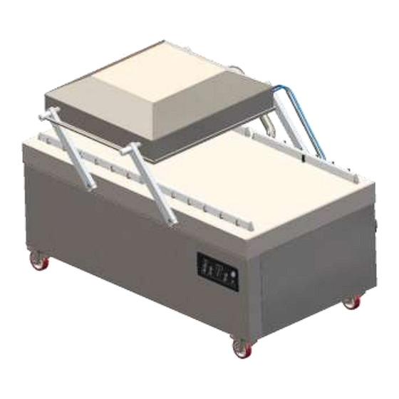
2. DESCRIPTION OF THE MACHINE FUNCTION This chapter provides an overview of the main components and functions If detailed information is available in this guide, you will be redirected to the specific sections The performance of your machine may differ from the figure below The figure below shows the main components of the system: Figure 1: Overview of the main components PART... - Page 14 PART DESCRIPTION SECTION Vacuum chamber The products to be packed will be placed on the worktable with the opening of the vacuum seal bag on the seal position On machines with two vacuum chambers one can take the packed product away and place new products on the free worktable during the vacuum cycle on the other side ...
-
Page 15: Description Of The Packaging Process / Machine Functions
2.1. Description of the packaging process / machine functions FUNCTION This chapter provides an overview of the process and the available machine functions For the functions H2O (H2O+), Gas (Gas+) and Seal 1-2 Cut-off, specific components must be installed in your machine before they can be activated. Please contact your supplier for more details ... - Page 16 STEP PROCESS PHASE OPERATION FUNCTION ICON After extracting the vacuum, a gas is injected into (optional) the chamber and the vacuum bag. This is to create a modified atmosphere to protect the shape or to increase the shelf life of the product. The value of the gas function can, depending on the control type, be set in %, mbar or hPa ...
- Page 17 STEP PROCESS PHASE OPERATION FUNCTION ICON Multi-cycle With multi-cycle it is possible to gradually extract vacuum vacuum and use gas. With this the oxygen content (optional) is reduced as well This function is available in machines with Multi Program Digital Control (MPDC) (see 5.5.1.5) ...
-
Page 18: General Functions
2.1.2. General Functions FUNCTION ICON OPERATION Cleaning the pump The pump cleaning program allows for a proper flushing of the pump. During the program, the pump and the oil will reach the operating temperature, so that the oil and the fluid will be separated and that any contamination is filtered. -
Page 19: The Seal System
2.2. The seal system FUNCTION The seal system closes the opening(s) of the bag(s) to maintain the vacuum and/or gas inside The remaining flap can optionally be cut off by the seal bar Figure 2: Overview of the seal system (above with seal bag, under with seal cylinder) USER MANUAL Marlin / Falcon / Polar... - Page 20 PART DESCRIPTION SECTION Seal bar The seal bar consists of the following components Seal wires: the sealing wires are heated for a certain period of time so that the open side of the vacuum bag will melt together during the sealing ...
-
Page 21: The Vacuum Pump
2.3. The vacuum pump FUNCTION De vacuum pump creates a vacuum in the chamber 40-300 m Figure 3: Overview of the pump (filter cover removed) PART DESCRIPTION SECTION Vacuum pump Creates the vacuum during the process Exhaust filter Filters the exhaust air and absorbs oil vapors ... -
Page 22: Gas Flushing (Optional)
2.4. Gas flushing (optional) FUNCTION For protection of the product it may be desirable to add a specific gas in the package after the air is removed. The machine can be provided with a gas connection optionally Installation details can be found in chapter 1 ATTENTION! ... -
Page 23: Figure 4: Overview Of The Electrical Installation
Figure 4: Overview of the electrical installation The machine consists of the following components SECTION/ PART DESCRIPTION LOCATION Power cable To connect the power supply to the machine Main switch Powers up the machine Circuit breaker Protection against overload or short circuit ... -
Page 24: Multi Program Digital Control (Mpdc)
SECTION/ PART DESCRIPTION LOCATION USB connection (only The USB connector is located on the side of the with ACS) control box that is located behind the back panel. In order to reach the USB connection, the back panel first has to be removed ... - Page 25 ELEMENT EXPLANATION ”Oil cleaning program” Operate the key to activate the pump cleaning program. This removes moisture from the oil in the vacuum pump. Moisture can be absorbed by the oil when the pump is only running short cycles or when you pack products containing moisture ...
-
Page 26: Advanced Control System (Acs)
2.7. Advanced Control System (ACS) FUNCTION The machine can be operated Programs can be changed See chapter 5 for instructions on operation and programming Figure 6: Control panel Advanced Control System (ACS) ELEMENT EXPLANATION Stop button The 'stop' button can be used during a packing cycle to interrupt the full cycle. -
Page 27: Settings Acs General
Figure 7: Four possible display modes 2.7.1. Settings ACS general FUNCTION To prevent unauthorized change and adjustment of settings, there are different levels of authorization. With an authorization code, you can access the different levels Users have limited access to change the settings of the machine. They can only change the printer settings using the printer icon in the navigation mode ... -
Page 28: Figure 8: Overview Settings
With the basic functions below, you can adjust the machine and/or function settings. WHAT TO DO ACTION RESULT Select another setting Press ‘up’▲ or ‘down’▼ Press ‘enter’ Edit selected setting Use ‘up’▲ or ‘down’▼ Adjust the variable ... -
Page 29: Import / Export Data
2.7.2. Import / Export data FUNCTION Data such as programs and labels can be imported and exported via the USB connection Exporting HACCP data is described in 2.7.3.2 Please contact your dealer if you want to exchange other data with the controller via the USB connection 2.7.3. -
Page 30: Export The Haccp Data Log
ATTENTION! The initials of the users should be entered. If this is not the case, tracing the machine operator is impossible 2.7.3.2. Export the HACCP data log ATTENTION! The memory can hold up to 100 entries. If the memory is full, you will be notified ... -
Page 31: Figure 9: Example Of An Exported Log
User:hm started 28-3-2013 16:42 Program 2=, Vac:360.5 mbar, Seal:0.3 sec, Labelnr.:1, Amount of cycles:2 User:he started 28-3-2013 16:43 Program 1=, Sequential Vac:2.0 mbar Seal:0.4 sec, Labelnr.:1, Amount of cycles:1 User:hm started 28-3-2013 16:44 Program 3=, Vac:2.0 mbar, Seal:2.5 sec, Labelnr.:1, Amount of cycles:2 User: started 28-3-2013 16:45 Program 3=, Vac:2.0 mbar, Seal:2.5 sec, Labelnr.:1, Amount of cycles:1 Figure 9: Example of an exported log... -
Page 32: Safety
3. SAFETY 3.1. General ATTENTION! Never pack products that can be damaged by vacuum Never pack living animals Warranty and/or liability expires if any damage is caused by repairs and/or modifications that are not authorized by the supplier or any of its distributors ... -
Page 33: During Normal Operation
3.2. During normal operation ATTENTION! Before starting, ensure that no work is done on the system and that it is ready to use the machine Unauthorized persons must not operate the machine. Checking this is the task of the machine operator(s) ... -
Page 34: Installation
4. INSTALLATION EXPLANATION Refer to chapter 1: Technical information for the correct specifications 4.1. Transport and placement ATTENTION! The machine must be moved and transported upwards Transportation of the machine with a crane is not possible Transportation of the machine with a forklift is possible as long as the machine is still on the pallet packaging ... -
Page 35: Connecting The Machine
4.2. Connecting the machine ATTENTION! Make sure that the voltage indicated on the machine plate corresponds to the mains voltage Attach the appropriate plug on the cable in accordance with local laws and connection data (see Chapter 1) ... -
Page 36: Operation
5. OPERATION ATTENTION Observe the instructions in chapter 3 for all work to be performed Failure to follow or ignore this may result in serious injury EXPLANATION The machine is equipped with sample programs with preset parameters It is possible to optimize a program for your products by changing the parameters of the program, see Chapter 5.5 5.1. -
Page 37: Production
5.2. Production WHAT TO DO ACTION RESULT Make sure the See chapter 5.1 machine is powered Select the program MPDC control: Press the program key (Figure 5:2) until the desired program appears on the display (Figure 5:1) ACS control: Use the control buttons ‘up’▲... -
Page 38: Stop Program
5.4. Stop program EXPLANATION Programs such as the packing program, or the oil cleaning program can be stopped at any time WHAT TO DO ACTION RESULT Press the “stop button” (Figure 5:8) Stop the program The program will be stopped and the vacuum (Figure 6:1) chamber will be... -
Page 39: Vacuum+ Option (Mpdc)
WHAT TO DO ACTION RESULT Select the program to Use the program ket (Figure 11:2) until be changed the correct program number appears in the display (Figure 11:1) Press the “reprog” key (Figure 11:3) Select the The program display programming mode flashes ... -
Page 40: Gas+ Option (Mpdc)
WHAT TO DO ACTION RESULT The display shows “99” Change the Press "+" or "-" (Figure 11:9/8) to adjust parameter vacuum to the value maximum (99%) The value is saved when you press the cursor key Select the parameter The display shows Press the cursor key once “OFF:”. -
Page 41: Red Meat Option (Mpdc)
WHAT TO DO ACTION RESULT Select the program on Use the program button (Figure 11:2) which you want to set until the correct program number appears liquid control in the display (Figure 11:1) Press the “reprog” key (Figure 11:3) Select the The program display programming mode... - Page 42 Programming the multi cycle steps WHAT TO DO ACTION RESULT Select the program on Use the program key (Figure 11:2) until which you want to set the correct program number appears in the multi cycle the display (Figure 11:1) ...
-
Page 43: External Vacuum Option (Mpdc)
5.5.1.6. External vacuum option (MPDC) EXPLANATION Only available as an option on Marlin Series With this function vacuum can be applied to special food packaging gastronorm containers outside the machine Depending on whether the machine has time or sensor control features, the vacuum value is set in seconds or % ... -
Page 44: Sleeper Time Option (Mpdc)
5.5.1.7. Sleeper time option (MPDC) EXPLANATION After the set time, the pump automatically switches off when the machine is not used during this period The pump will automatically start when a new vacuum cycle is started The Sleeper time feature is set to 10 minutes by default ... -
Page 45: Programming The Acs Control On Your Pc
The imported data can be created using the online software for programming. You will find this software on our website on the 'Support' page: http://www.henkelman.com/en/support/downloads Or contact your supplier. Creating a program or label and import them into the machine: ... - Page 46 Start a new program by: Select a program or label you want to change You can also import existing programs and/or labels that you like to change in: Select a file to import Then select a program or a label and click on the 'GO' button ...
-
Page 47: Options (Acs)
5.5.2.2. Options (ACS) EXPLANATION The options that are built into the machine can be enabled or disabled at the settings menu by the owner (login as owner) (See section 2.7.1) Subsequently the options in the various programs can be programmed 5.5.2.3. -
Page 48: Directive For Function Values
WHAT TO DO ACTION RESULT Disconnect the Hose will be Slide the valve of the adapter in the external vacuum hose disconnected from the direction of the package (open position) from the container container and can be and remove the hose removed 5.6. - Page 49 FUNCTION RANGE CONDITIONS This is the time in which the seal wire and/or cutting wire Seal time 0,1-4,0 sec is heated. The longer the time, the more heat is being 1-2 cutting time transferred to the bag The length of time in which air is introduced to the Soft air 1-20 sec chamber after sealing.
-
Page 50: Figure 15: Water Vapour Line
Figure 15: Water vapour line USER MANUAL Marlin / Falcon / Polar Version: MFP-EN-0 04-12-14... -
Page 51: Maintenance
6. MAINTENANCE ATTENTION! Always disconnect the power supply by switching the main switch to "0" or by unplugging the power cord Always disconnect the external pressure (if applicable) Test the machine after maintenance or repairs, so it is certain that the machine can be safely used ... -
Page 52: Cleaning The Machine
ACTIVITY LUBRICANT SECTION Replacements Replace the sealing wires Replace the silicone rubber of the silicone holders Replace the lid seal Replace the exhaust filter Replace the oil filter Please contact your supplier for a professional service Replace the plastic lid (if applicable) 6.2. -
Page 53: Oil Cleaning Program
6.3. Oil cleaning program EXPLANATION The oil cleaning program will let the vacuum pump run for 15 minutes. During the program, the pump and the oil will reach the operating temperature. The oil absorbs fluid in the pump. The high temperature ensures that the moisture evaporates in the pump and reduces the risk of corrosion ... -
Page 54: Replacing The Exhaust Filter (Maintenance Of Vacuum Pump)
Add oil WHAT TO DO ACTION RESULT Add oil Remove the oil filler plug (Figure 3:5) Add oil until the oil level is between the "max" and "min" level (Figure 3:3) Replace the oil filler plug Replacing oil and oil filter WHAT TO DO ACTION RESULT... -
Page 55: Figure 16: Replacing The Exhaust Filter
40-300 m pump Figure 16: Replacing the exhaust filter WHAT TO DO ACTION RESULT Remove the exhaust Remove the filter cover (Figure 16:4) from filter the vacuum pump (Figure 16:1) Remove the leaf spring (Figure 16:3) Remove the old filter (Figure 16:2) ... -
Page 56: Replacing The Sealing Wire
6.6. Replacing the sealing wire EXPLANATION Depending on your machine specification you can have one of the following (combinations of) seal elements: • Double seal: Two sealing wires • Cut-off seal: One sealing wire and one cutting wire • Wide sealing: One wide sealing wire •... - Page 57 WHAT TO DO ACTION RESULT Remove the seal bar Remove the seal bar from the holders from the lid (Figure 18:4) by disconnecting the (for metal lid) electrical connection plugs (Figure 18:2) (2x) and remove the M6 screws (Figure 17:3) ...
-
Page 58: Replacing The Silicone Rubber On The Silicone Holders
6.7. Replacing the silicone rubber on the silicone holders EXPLANATION In order to obtain a seal of good quality, the rubber should not be damaged and the surface must be flat Damage may be caused by burning the seal wire or mechanical contact ... -
Page 59: Replacing The Lid Gasket
6.8. Replacing the lid gasket EXPLANATION The lid gasket ensures that the vacuum chamber is completely closed off during the machine cycle. This is essential for the achievement of a maximum vacuum level. The lid gasket will wear out due to extreme pressure differences and should be changed regularly ... -
Page 60: Inspecting The Lid Springs
6.9. Inspecting the lid springs EXPLANATION Check the fastenings of the lid springs for wear, corrosion and damage Check the lid springs for wear and damage In the case of irregularities, please contact your supplier USER MANUAL Marlin / Falcon / Polar Version: MFP-EN-0 04-12-14... -
Page 61: Troubleshooting
7. TROUBLESHOOTING The tables below show the possible interference with the corresponding cause and action to be taken. MALFUNCTION ACTIVITY SECTION Control panel does not illuminate Connect the machine to the power supply Check the circuit breaker The control panel is on but there is no Please contact Check / adjust the micro switch of the lid... - Page 62 Error messages for MPDC F1 in display Check / adjust the micro switch of the lid Please contact your supplier Make sure that the pump is running correctly F2 in display Check if the cover is opened and restart the Please contact machine (MPDC with sensor control)
-
Page 63: Warranty Conditions
The warranty is subject to the following limitations. The warranty period for products supplied by Henkelman is 3 years from the date of the purchase document. This warranty is limited to manufacturing and machine errors, and therefore does not cover malfunctions due to a component of the product that has been exposed to any type of wear. -
Page 64: Dispose As Waste
9. DISPOSE AS WASTE Do not dispose oil and components with the household waste. Ensure that at the replacement of parts or oil after the lifecycle, that all materials are collected and destroyed or recycled in a legal and environmentally friendly manner. USER MANUAL Marlin / Falcon / Polar Version: MFP-EN-0... -
Page 65: Appendix
10. APPENDIX 10.1. Log This log should include among other things: ● Annual maintenance ● Big replacements and emergencies ● Modifications ● Tests of the emergency stop buttons and safety devices DATE: EXECUTED BY: DESCRIPTION: (AUTORITY, (NATURE OF THE ACTIVITIES, WHAT IS REPLACED) TECHNICIAN) USER MANUAL Marlin / Falcon / Polar... - Page 66 DATE: EXECUTED BY: DESCRIPTION: (AUTORITY, (NATURE OF THE ACTIVITIES, WHAT IS REPLACED) TECHNICIAN) USER MANUAL Marlin / Falcon / Polar Version: MFP-EN-0 04-12-14...
- Page 67 USER MANUAL Marlin / Falcon / Polar Version: MFP-EN-0 04-12-14...
- Page 68 USER MANUAL Marlin / Falcon / Polar Version: MFP-EN-0 04-12-14...
Need help?
Do you have a question about the Marlin 46 and is the answer not in the manual?
Questions and answers