
Related Manuals for Henkelman Jumbo Series


Summary of Contents for Henkelman Jumbo Series
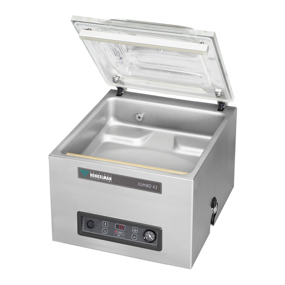
- Page 1 Vacuum Packaging Machine Jumbo User Manual Art No. 0894622 Original Instructions for Use © Henkelman 2017-2018...
- Page 2 Henkelman BV accepts no liability for damage and/or problems arising from the use of spare parts not supplied by Henkelman BV. This user manual has been compiled with all possible care. Henkelman BV assumes no responsibility for any errors in this manual and/or the consequences of an erroneous interpretation of the instructions.
-
Page 3: Table Of Contents
2.3 Warnings During Use......................10 2.4 Warnings for Operating Personnel..................11 3 Introduction..........................12 4 Description of the Machine.......................13 4.1 Jumbo series........................13 4.1.1 Overview of the Main Components................14 4.2 Description of the Packaging Process/Machine Functions..........15 4.2.1 Packaging Process/Machine Functions................15 4.2.2 General Functions......................15 4.3 Sealing System........................ - Page 4 7.8.4 Running the Pump Cleaning Programme..............33 8 Troubleshooting and Error Codes................... 34 9 Terms of Warranty........................36 10 Disposal.............................37 11 Appendices..........................38 11.1 Technical Data........................38 11.1.1 Jumbo series......................38 11.2 Electrical Installation......................40 11.3 Vapour Pressure Curve of Water..................41 11.4 Logbook..........................42 Contents...
-
Page 5: List Of Figures
List of Figures Figure 1: Overview of the Main Components................. 14 Figure 2: Overview of the Sealing System..................16 Figure 3: Control Panel of the 1-PCS.....................19 Figure 4: External Vacuum Adapter Set (1-PCS)................22 Figure 5: Removing the Sealing Bar....................26 Figure 6: Replacing the Sealing Wire..................... -
Page 6: Preamble
Preamble This is the manual for your Henkelman vacuum packaging machine series: Jumbo. This manual is intended for anyone who works with or services the machine. This manual contains information and instructions for installation, operation and maintenance of the machine. We recommend that you carefully read this manual before use and follow the procedures and instructions strictly. -
Page 7: Storing The Manual
The warranty is subject to the following limitations. The warranty period for products supplied by Henkelman BV is 3 years from the date indicated on the purchase document. This warranty is limited to manufacturing and machining defects and therefore does not cover breakdowns involving any part of the product that is exposed to any form of wear and tear. -
Page 8: Terms And Abbreviations
• With the exception of the applicable legal regulations of public order and good faith, we are not liable to pay for any damage of any sort whatsoever to the counterparty or to third parties, directly or indirectly, including lost profits, damage to movable or immovable property or personal injury. -
Page 9: Safety
Safety Your vacuum packaging machine has been carefully designed and expertly built to be operated safely. This is corroborated by the EC Declaration of Conformity. However, there are always dangers and safety risks that cannot be eliminated. These dangers and risks are the result of the use functions of the machine and operation of the machine by the user. -
Page 10: Warnings During Use
• Prevent water from entering the ventilation inlet of the chamber or the exhaust of the pump. This causes irreversible damage to the pump. • The work space around the machine must be safe. The owner of the machine must take the necessary precautions to operate the machine safely. -
Page 11: Warnings For Operating Personnel
Warnings for Operating Personnel • Operating personnel must be 18 years or older. • Only authorised persons are allowed to perform work on or with the machine. • Personnel may only perform work for which it was trained. This applies to both maintenance and normal use. -
Page 12: Introduction
Introduction Henkelman BV is a supplier of ultra-modern vacuum packaging machines. Our machines are developed and manufactured to meet the highest standards. They combine a sleekly built and functional design with optimal ease of use and a long service life. After mounting the plug, it is just a matter of "plug &... -
Page 13: Description Of The Machine
If detailed information is available in this manual, you will be referred to the specific sections. Jumbo series Basic vacuum packaging machines for basic packaging needs. The Jumbo series represent a range of compact table-top models. All Jumbo models are equipped: •... -
Page 14: Overview Of The Main Components
4.1.1 Overview of the Main Components The figure below shows the main components of the Jumbo series. The model shown may differ from your machine. Figure 1: Overview of the Main Components The lid closes the vacuum chamber during the application of the vacuum. A rubber is mounted in the lid to ensure proper closing. -
Page 15: Description Of The Packaging Process/Machine Functions
Description of the Packaging Process/Machine Functions This section provides an overview of the packaging process and available machine functions. 4.2.1 Packaging Process/Machine Functions This section describes the packaging process and the machine functions. See Operation on page 19 for the realization of the specific steps of the procedure. Step Process phase Operation... -
Page 16: Sealing System
Function Pictogram Operation External Vacu- This function allows special food containers to be vacuumed out- side the machine. The options to set the vacuum value are the same as for stand- ard vacuuming (see External Vacuum (optional) on page 22). Sealing System The sealing system closes the opening(s) of the bag to retain the vacuum and/or gas in the bag. -
Page 17: Installation
Installation Consult Technical Data on page 38 for the specifications of the machine. Before installing the machine, carefully read the safety instructions in Safety on page 9. Failure to follow or disregard of the safety instructions may result in serious injury. Transportation and Installation The machine must be moved and transported in an upright position. -
Page 18: Prior To The First Use
• The power cable must be free at all times, and nothing may be placed on it. • Immediately replace the power cable if damaged. Prior to the First Use See Vacuum Pump maintenance on page 28 for more information how to perform these steps. Prior to the first use, the following steps must be performed: Failure to do so may result in unrepairable damage to the machine. -
Page 19: Operation
Operation Depending on the configuration of the vacuum packaging machine it is equipped with one of the following control systems: • 1-Programme Control System (1-PCS) Read the appropriate section how to operate the vacuum packaging machine. • All persons responsible for the operation of this machine must at least fully read and understand the chapters Safety on page 9 and Operation on page 19. -
Page 20: Starting The Machine
Function display The LED light in front of the function lights up if the function is active during the programme cycle or if the function is selected in the programming mode. – / STOP button This is used to interrupt the entire cycle during a packaging cycle. All functions are skipped and the cycle is terminated. -
Page 21: Changing The Programme Settings
Terminate the programme. Press the Press the STOP button. The programme will be terminated and the vacuum chamber is decompressed. 6.1.6 Changing the Programme Settings This section describes the units and limits of the parameters and how parameters can be adjusted. See Operating Elements on page 19 for an overview of the operating elements of the 1-PCS. -
Page 22: Seal
6.1.6.3 Seal This is the time that the sealing wire and/or the cut-off wire are heated. The longer the time, the more heat is transferred to the bag. Use the Cursor key to scroll to the parameter Seal. The LED in front of the selected function will light up. Press the –... -
Page 23: Guideline For Function Values
6.1.7 Guideline for Function Values Values can be set for each function. In order to understand the consequence of the set value, the table below explains the consequences of giving a low or high value for each function. Function Range Conditions Vacuum 30-99 % or... -
Page 24: Maintenance
Maintenance When carrying out maintenance work, always observe the following safety rules. • Only trained technicians are authorised to perform the described maintenance activities. • Always disconnect the power supply by disconnecting the plug. • Test the machine after carrying out maintenance work or repairs to make sure the machine can be used safely. -
Page 25: Cleaning The Machine
Activity * 1-D 1-W 6-M 1-Y 4-Y Check the plastic lid for cracks (if applicable). Inspect the lid springs. Pay additional attention to damage and the fastenings of the lid springs. Lubrication Replace the oil of the vacuum pump. See Technical Data on page 38 for the type of oil. -
Page 26: Figure 5: Removing The Sealing Bar
Figure 5: Removing the Sealing Bar Remove the sealing bar by lifting it from the cylinders. See Figure 5: Removing the Sealing Bar on page 26. Figure 6: Replacing the Sealing Wire Remove the Teflon tape (1) that protects the sealing wire. Remove the screws (2) at the bottom of the sealing bar and remove the sealing wires (3). -
Page 27: Replacing The Silicone Rubber Of The Silicone Holders
Cut a piece of Teflon tape at the length of the sealing bar plus approximately 5 cm. Attach the tape over the sealing wires on the sealing bar evenly and without folds. Cut the tape. Place the sealing bar back in its position. Replacing the Silicone Rubber of the Silicone Holders To ensure a seal of good quality, the silicone rubber may not be damaged and the surface must be smooth. -
Page 28: Inspecting The Lid Springs
Figure 8: Replacing the Lid Gasket Pull the old gasket loose to remove it. Cut a new piece of rubber. Preferably cut the new piece of rubber slightly longer than the old piece. The edges must be cut straight. If the lid gasket is too short or too long, this may cause problems when closing the lid or it may cause leakage. -
Page 29: Pump 4 M /H
7.8.1.1 Pump 4 m Figure 9: Overview of the Pump Vacuum pump - Creates the vacuum for the process. Oil exhaust filter - Filters the air by capturing oil vapours. Oil sight glass - Indicates the maximum and minimum oil levels of the vacuum pump. Oil drain plug - Removing the oil drain plug allows the oil to be drained. -
Page 30: Pump 16 - 21 M
Oil filler plug - Removing the oil filler plug allows the oil to be refilled. 7.8.1.3 Pump 16 - 21 m Figure 11: Overview of the Pump Vacuum pump - Creates the vacuum for the process. Oil exhaust filter - Filters the air by capturing oil vapours. Oil sight glass - Indicates the maximum and minimum oil levels of the vacuum pump. -
Page 31: Replacing The Oil Exhaust Filter
Remove the oil filler plug. Add oil until the oil level is between the minimum and maximum levels of the oil sight glass. Replace the oil filler plug. 7.8.3 Replacing the Oil Exhaust Filter The oil exhaust filter prevents oil vapours from being emitted from the vacuum pump with the exhaust air. -
Page 32: Pump 8 M /H
7.8.3.2 Pump 8 m Figure 13: Replacing the Oil Exhaust Filter Follow the steps below to remove the old oil exhaust filter: Remove the filter cover (3) of the vacuum pump (1) and put it aside. Remove the oil exhaust filter (2) from the vacuum pump. Follow the steps below to install a new oil exhaust filter: Turn the new filter into the vacuum pump. -
Page 33: Running The Pump Cleaning Programme
Follow the steps below to remove the old oil exhaust filter: Remove the filter cover (4) of the vacuum pump (1) and put it aside. Remove the leaf spring (3) and put it aside. Remove the old filter (2). Follow the steps below to install a new oil exhaust filter: Insert the new filter into the vacuum pump. -
Page 34: Troubleshooting And Error Codes
Troubleshooting and Error Codes The tables below show the possible malfunctions and the corresponding causes as well as the steps to be taken. Malfunction Activity More information Control panel does not illumin- • Connect the machine to the Connecting the Machine on ate. - Page 35 Malfunction Activity More information Vacuum bag is not sealed cor- • Check the seal settings of Operation on page 19. rectly. the programme and adjust Replacing the Sealing Wire on them. page 25. • Check/replace the Teflon Replacing the Silicone Rubber tape and the sealing wires.
-
Page 36: Terms Of Warranty
Terms of Warranty • The responsibility of Henkelman BV is limited to replacing defective parts; we shall not acknowledge claims for any other kind of damage or costs. • The warranty automatically expires in case of overdue or poor maintenance. -
Page 37: Disposal
Disposal Do not dispose of oil and components as household waste. When repla- cing oil or components at the end of the service life, ensure that all ma- terials are collected and disposed or reused in a legal and environment- ally sound manner. -
Page 38: Appendices
Appendices 11.1 Technical Data 11.1.1 Jumbo series Jumbo Mini Jumbo Jumbo Plus General Ambient temperature during operation 5 to 30°C 5 to 30°C 5 to 30°C Machine working conditions: relative 10-90% 10-90% 10-90% humidity (non-condensing) Sound emission < 70 dB(A) <... - Page 39 Jumbo 42XL 42XXL General Ambient temperature during 5 to 30°C 5 to 30°C 5 to 30°C 5 to 30°C operation Machine working conditions: 10-90% 10-90% 10-90% 10-90% relative humidity (non-condens- ing) Sound emission < 70 dB(A) < 70 dB(A) < 70 dB(A) <...
-
Page 40: Electrical Installation
11.2 Electrical Installation The electrical installation provides power for the vacuum pump, the seal system and the operation of the machine. See the electrical diagram for the further structure and operation of the electrical installation. Please contact your supplier for the electrical diagram. Only a technical expert may perform work on the electrical installation. -
Page 41: Vapour Pressure Curve Of Water
11.3 Vapour Pressure Curve of Water Figure 16: Vapour Pressure Curve of Water Appendices... -
Page 42: Logbook
11.4 Logbook This logbook must include: • Annual maintenance work • Major replacements and emergencies • Modifications • Tests of the emergency stop buttons and safety devices Date: Performed by: Description: (authority, technician) (nature of the activities, which parts have been replaced) Appendices... - Page 43 Date: Performed by: Description: (authority, technician) (nature of the activities, which parts have been replaced) Appendices...
- Page 44 Henkelman BV Titaniumlaan 10 5221 CK 's-Hertogenbosch +31 (0)73 621 3671 +31 (0)73 622 1318 www.henkelman.com info@henkelman.com...
Need help?
Do you have a question about the Jumbo Series and is the answer not in the manual?
Questions and answers