
Subscribe to Our Youtube Channel
Related Manuals for Henkelman Marlin


Summary of Contents for Henkelman Marlin
- Page 1 Vacuum Packaging Machine Marlin, Falcon, Polar User Manual Art No. 0895011 Original Instructions for Use © Henkelman 2017...
- Page 2 Henkelman BV accepts no liability for damage and/or problems arising from the use of spare parts not supplied by Henkelman BV. This user manual has been compiled with all possible care. Henkelman BV assumes no responsibility for any errors in this manual and/or the consequences of an erroneous interpretation of the instructions.
-
Page 3: Table Of Contents
Contents List of Figures..........................6 1 Preamble............................7 2 Safety.............................8 2.1 List of the Symbols Used in this Manual................8 2.2 Pictograms on the Machine....................8 2.3 General Warnings........................9 2.4 Warnings During Use......................10 2.5 Warnings for Operating Personnel..................10 3 Introduction..........................12 4 Description of the Machine.......................13 4.1 Overview of the Main Components..................13... - Page 4 6.7.1.4 Gas+ (optional)..................... 35 6.7.1.5 Liquid Control (optional)..................35 6.7.1.6 Liquid Control+ (optional)..................35 6.7.1.7 Red Meat (optional)....................36 6.7.1.8 Multi-Cycle Vacuum (optional)................36 6.7.1.9 Seal........................36 6.7.1.10 Soft-Air (optional for the Falcon)................ 37 6.7.1.11 External Vacuum (optional)................37 6.7.1.12 Sleeper Option....................38 6.7.2 Advanced Control System (ACS)................. 38 6.7.2.1 Programming the ACS Control Using the PC............
- Page 5 10 Disposal.............................62 11 Appendices..........................63 11.1 Technical Data........................63 11.1.1 Technical Data Marlin....................63 11.1.2 Technical Data Falcon....................64 11.1.3 Technical Data Polar....................66 11.2 Example Programs......................70 11.3 Logbook..........................72 11.4 EC Declaration of Conformity.................... 74 11.5 Replacing a Printer Roll..................... 75 11.6 Aligning the Printer......................76...
-
Page 6: List Of Figures
List of Figures Figure 1: Overview of the Main Components................. 13 Figure 2: Overview of the Sealing System (Including Sealing Cylinder).........19 Figure 3: Overview of the Sealing System (Including Seal Bag)............ 19 Figure 4: Overview of the Pump..................... 20 Figure 5: Overview of the Electrical Installation................21 Figure 6: Direction of Rotation of the Vacuum Pump.............. -
Page 7: Preamble
Preamble This is the manual for your Henkelman vacuum packaging machine. This manual is intended for anyone who works with or services the machine. This manual contains information and instructions for installation, operation and maintenance of the machine. We recommend that you carefully read this manual before use and follow the procedures and instructions strictly. -
Page 8: Safety
Safety Your vacuum packaging machine has been carefully designed and expertly built to be operated safely. This is corroborated by the EC Declaration of Conformity. However, there are always dangers and safety risks that cannot be eliminated. These dangers and risks are the result of the use functions of the machine and operation of the machine by the user. -
Page 9: General Warnings
Warning sign "Gas Connection" (optional) Forbidden to connect oxygen • Is located on the back of the machine Warning sign "Gas Connection" (optional) Maximum allowed gas pressure of the gas flush system • Is located on the back of the machine Warning sign "Seal Pressure Connector"... -
Page 10: Warnings During Use
• The machine has been designed in such a way that production is safe under normal ambient conditions. • The owner of the machine must ensure that the instructions in this manual are actually complied with. • The available safety devices may not be removed. •... - Page 11 • If an operator notices errors or risks or disagrees with safety measures, he or she should report this to the owner or manager. • Safety shoes are mandatory. • Appropriate work clothing is mandatory. • All personnel must obey the safety regulations to avoid danger to themselves and others.
-
Page 12: Introduction
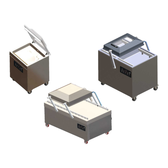
"plug & pack". The clever design ensures compliance with the hygiene standards at all times. The Marlin, Falcon and Polar series are floor models with various options suitable for a variety of applications. These machines have several programs and options for optimal packaging. -
Page 13: Description Of The Machine
Description of the Machine This section provides an overview of the main components and functions. If detailed information is available in this manual, you will be referred to the specific sections. Overview of the Main Components The figure below shows the main components of the system. The model shown may differ from your machine. -
Page 14: Description Of The Packaging Process/Machine Functions
Control panel This serves to operate the available control functions. Depending on your model, your machine will have the 10-program control system or the Advanced Control System (ACS). Seal system Depending on the model, one, two or three sealing bars are mounted in the vacuum chamber. These close the vacuum bag. - Page 15 Step Process phase Operation Vacuum During the cycle, the air is removed from the chamber until the set time or pressure has been reached, depending on the selected model. Applying vacuum until a set value is reached is only possible if your machine is sensor-controlled (optional for 10-program control system).
- Page 16 Step Process phase Operation bursting, thus contaminating the seal, the chamber, and the oil in the pump. See Liquid Control (optional) on page 35. Liquid Control+ Liquid Control+ is only available if your machine is equipped (optional) with the Liquid Control option. The Liquid Control+ function allows you to continue the vacuum process for a certain time after the evaporation point has been reached.
- Page 17 Step Process phase Operation Vacuum+. The intermediate ventilation steps have a fixed value of 40%. After the last step, sealing takes place. Liquid Control: It is also possible to enable Liquid Control. This function will then only be active during the last vacuuming step.
-
Page 18: General Functions
Step Process phase Operation Removing the The operator can remove the packaged product from the product work surface. 4.2.2 General Functions Function Pictogram Operation Cleaning of the The pump cleaning program ensures that the pump is thoroughly oil pump rinsed. During the program, the pump and oil reach the operating temperature, so the oil and moisture are separated and any contamination is filtered. -
Page 19: Sealing System
Sealing System The sealing system closes the opening(s) of the bag to retain the vacuum and/or gas in the bag. The end of the bag can optionally be cut off by the sealing bar. Figure 3: Overview of the Sealing Figure 2: Overview of the Sealing System (Including Seal Bag) System (Including Sealing Cylinder) -
Page 20: Vacuum Pump
Vacuum Pump The vacuum pump creates the vacuum. Figure 4: Overview of the Pump Vacuum pump - Creates the vacuum for the process. Oil exhaust filter - Filters the air by capturing oil vapours. Oil sight glass - Indicates the maximum and minimum oil levels of the vacuum pump. Oil drain plug - Removing the oil drain plug allows the oil to be drained. -
Page 21: Figure 5: Overview Of The Electrical Installation
The machine consists of the following electrical components: Figure 5: Overview of the Electrical Installation Power connection and cable This serves to connect the machine to the power supply. The machine is supplied without an electrical plug. Main switch This switch is used to switch the machine ON and OFF. Circuit breaker Protects against overload or a short circuit. - Page 22 USB connector (only in case of ACS control) The USB connector is located on the side of the control box, which is located behind the rear wall. Reaching the USB connector requires removing the rear wall. After opening the cover of the USB connector, the machine is no longer waterproof (IP65).
-
Page 23: Installation
Installation Consult Technical Data on page 63 for the specifications of the machine. Before installing the machine, carefully read the safety instructions in Safety on page 8. Failure to follow or disregard of the safety instructions may result in serious injury. Transportation and Installation The machine must be moved and transported in an upright position. -
Page 24: Prior To The First Use
Operating the machine with an incorrect direction of rotation results in damage to the pump, in which case no vacuum can be created. After connecting the machine to a different three- phase power supply, the direction of rotation should be checked again. If the direction of rotation is incorrect, two phases in the plug must be interchanged. -
Page 25: Operation
Operation The machine is equipped with sample programs with preset parameters (see Example Programs on page 70). It is possible to optimise a program for your products by modifying the parameters of a program, see Changing the Program Settings on page 33. •... -
Page 26: Operating Elements Of The Advanced Control System (Acs)
Pump cleaning program button This is used to activate the pump cleaning program. Moisture can be absorbed by the oil when the pump is running only short cycles or when you are packaging moisture-containing products. This program removes moisture from the oil of the vacuum pump. See Running the Pump Cleaning Program on page 52 for instructions. -
Page 27: Changing The Acs Settings
On/Off button Serves to turn the control on or off. Display The display has four possible modes: See Figure 9: Possible Display Modes on page 27 and Figure 10: Possible Display Modes on page 27. • Start-up mode: displays the current date and time when starting the machine. It also displays the installed software version. -
Page 28: Figure 11: Overview Of The Menus
be opened. When logged in, the function settings can also be changed. To do so, return to the navigation mode by pressing ◄. The machine remembers the last authorisation code used, even when the machine has been turned off. Therefore, it may be necessary to manually change the authorisation setting when you are done. - Page 29 Settings 1.3 Date & 1.5 Screen 1.7 Program 1.8 Data log 1.1 Printer 1.2 Units 1.6 Options Time Language saver names Sleeper Screen Pressure Data log ID Printer Date format English saver option Program unit On/Off On/Off On/Off (only on floor Temperature Time format...
-
Page 30: Importing/Exporting Data
6.2.2 Importing/Exporting Data Data such as programs and labels can be imported and exported via the USB connection. 6.2.3 Data Log ID The control system is provided with the option to store the production information. The data log is stored in lined entries. Each entry consists of: •... -
Page 31: Exporting Data Log
6.2.3.2 Exporting Data Log The memory can store up to 100 entries. If the memory is full, you will receive a message. The data log will first need to be exported before you can continue your work. You can export the data at any time. -
Page 32: Starting The Machine
Label Number The label that was printed for this package. Number of Cycles The number of cycles run from the start time. Starting the Machine Plug in the machine. Turn the main switch to the ON position (see Electrical Installation on page 20) to turn on the machine. -
Page 33: Terminating A Program
Terminating a Program Programs such as the packaging program or the pump cleaning program can be terminated at any time. Terminate the program. 10-program control system Press the – / STOP button. Press the STOP button. The program will be terminated and the vacuum chamber is decompressed. Changing the Program Settings 6.7.1 10-Program Control System... -
Page 34: Vacuum+ (Optional)
6.7.1.2 Vacuum+ (optional) If air is trapped in the product, it may be desirable to extend the vacuuming time after the maximum vacuum has been reached. This to allow entrapped air to escape from the product. The Vacuum+ time is set in seconds. If a Vacuum+ time has been set, a dot will appear in the bottom right of the parameter display. -
Page 35: Gas+ (Optional)
6.7.1.4 Gas+ (optional) The Gas+ option only applies if the machine is equipped with the gas option. For some products it may be desirable to insert additional gas into the packaging to create a "balloon packaging". This allows for a better protection of a fragile product. The recommended value for Gas+ is 0.7 seconds. If the Gas+ option is enabled, a dot will appear in the bottom right of the program display. -
Page 36: Red Meat (Optional)
Press the – / STOP button and the + / VACUUM STOP button to adjust the value of Liquid Control+. When setting a value, a dot will appear in the bottom right of the parameter display. Press the REPROG button to activate the new parameter. The function display will stop flashing. -
Page 37: Soft-Air (Optional For The Falcon)
Depending on whether the machine is time or sensor-controlled, the vacuum value is set in seconds or %. External Vacuum is only available on the Marlin series. With the External Vacuum program, you can program as with any other program. See Changing the Program Settings on page 33. -
Page 38: Sleeper Option
Program the External Vacuum program according to the steps specified in 10-Program Control System on page 33. Connect the external vacuum hose to the machine by placing the adapter over the suction inlet (1) in the vacuum chamber. Connect the external vacuum hose to the packaging. Connect the adapter (3) of the external vacuum hose to the valve of the packaging. -
Page 39: Programming The Acs Control Using The Pc
You can import labels and programs from a USB stick by inserting the stick into the USB port of your machine. You can create the data to be imported using the online software that is available on the Support section of our website: http://www.henkelman.com/en/vacuum-packaging/advanced- control-system. -
Page 40: Functions
Click on the link of the LX Software. Click on Select a program or label you want to change to start a new program. You can also click on Select a file to import to import existing programs and/or labels from the machine. -
Page 41: Gas (Optional)
Set the value of the Vacuum to the maximum (99.8%) as described in Vacuum on page 40. Enable Vacuum+. Use the cursor keys ▲ and ▼ to go to the value for the Vacuum+ and press Enter. Set the desired value using the cursor keys ▲ and ▼ and press Enter. Press the cursor key ◄... -
Page 42: Liquid Control (Optional)
6.7.2.7 Liquid Control (optional) The Liquid Control option can be enabled or disabled for each program. If the product reaches the boiling point before the set vacuum is reached, the machine will proceed to the next step of the cycle. To set the Liquid Control option, follow the steps below: Press the cursor keys ◄... -
Page 43: Sequential Vacuum (Optional)
Press the cursor keys ◄ and ► and select the program Red Meat. Press Enter to open the menu. If Red Meat is not enabled, enable it. Press Enter and use cursor key ▲ and ▼ to turn ON Red Meat. -
Page 44: Tenderising (Optional)
Use the cursor keys ▲ and ▼ to go to the value for the Vacuum of the last step and press Enter. Use the cursor keys ▲ and ▼ to go to the number of steps and press Enter. Use the cursor keys ▲ and ▼ to set the number of steps and press Enter. Press the cursor key ◄... -
Page 45: Soft-Air (Optional For The Falcon)
The External Vacuum function allows special food containers to be vacuumed outside the machine. The packaging is vacuumed until a vacuum of 99.8% is reached. External Vacuum is only available on the Marlin series. Check in advance whether the relevant food container can withstand and hold a vacuum. -
Page 46: Sleeper Option
Press the cursor keys and select the program External Vacuum to start vacuuming. The packaging is vacuumed until the maximum vacuum is reached. Slide the sliding valve of the adapter towards the packaging (open position) and remove the external vacuum hose from the packaging. 6.7.2.16 Sleeper Option If the Sleeper option is enabled, the pump will automatically shut off after the set time has elapsed... - Page 47 Function Range Conditions Gas+ 0.1 – 1 second For some products it may be desirable to insert additional gas into the packaging to create a "balloon packaging". This allows for a better protection of a fragile product. The recommended value for Gas+ is 0.7 seconds.
- Page 48 Function Range Conditions Tenderising 30 – 99.8% Only in case of ACS control. This is the value at which the tenderising takes place. The duration of the Time: 0 – 30 tenderising process can also be set. minutes Seal time 0.1 –...
-
Page 49: Printer (Acs Only)
Figure 16: Vapour Pressure Curve of Water Printer (ACS only) A printer can be connected to the machine to print package labels. From software version 90, the mounted sensor is automatically detected. A message is displayed if you close the lid and no sensor is detected. 6.9.1 Connecting a Printer To connect a printer to the machine, follow the steps below:... - Page 50 Customer name Label number Name Info Use by / Storage life Storage temperature Print customer name Y/N Print info Y/N Print achieved vacuum Y/N 10. Print expiry date Y/N 11. Print user Y/N 12. Print storage temperature Y/N Once the printer is selected and the required information for the label is entered, the printer can be activated on each separate program.
-
Page 51: Maintenance
Maintenance When carrying out maintenance work, always observe the following safety rules. • Only trained technicians are authorised to perform the described maintenance activities. • Always disconnect the power supply by turning the main switch to "0" or disconnecting the plug. •... -
Page 52: Cleaning The Machine
Activity * 1-D 1-W 6-M 1-Y 4-Y Replace the oil exhaust filter. Replace the oil filter. Contact your dealer for professional servicing. Replace the plastic lid (if applicable). * 1-D = Daily, 1-W = Weekly, 6-M = Every 6 months, 1-Y = Annually, 4-Y = Every 4 years Cleaning the Machine Never clean the machine using a high pressure cleaner. -
Page 53: Replacing The Oil Exhaust Filter
If the machine remains unused for a prolonged period of time, the oil must be removed from the pump. This is necessary because moisture and dirt in the oil may affect the pump, causing the pump to jam at the next use. The oil in the vacuum pump may be hot. -
Page 54: Pump 40-300 M
7.5.1 Pump 40-300 m Figure 17: Replacing the Oil Exhaust Filter (Pump 40-300 m Follow the steps below to remove the old oil exhaust filter: Remove the filter cover (4) of the vacuum pump (1) and put it aside. Remove the leaf spring (3) and put it aside. Remove the old filter (2). -
Page 55: Figure 18: Removing The Sealing Bar (Plastic Lid)
Replace the sealing wires if the wire and/or the Teflon tape are damaged, or as specified in Maintenance Schedule on page 51. On machines with a plastic lid, the sealing bars are mounted on cylinders (Figure 18: Removing the Sealing Bar (Plastic Lid) on page 55). On machines with a metal lid, the sealing bars are mounted in the lid (Figure 19: Removing the Sealing Bar (Metal Lid) on page 55). -
Page 56: Replacing The Silicone Rubber Of The Silicone Holders
Replace the Teflon tape on the sealing bar. Pull the Teflon tape from the top of the sealing bar (4). Clean the sealing bar with a dust-free cloth. Apply a new piece of Teflon tape of the same length on the sealing bar. Replace the sealing wires. -
Page 57: Replacing The Lid Gasket
Install the new piece of silicone rubber by pressing it into the recess of the silicone holder. Ensure that the silicone rubber is fully and uniformly placed in the recess. It is also important that the surface of the silicone rubber is smooth after it is in place, and that it shows no signs of stress. - Page 58 In the case of irregularities, please contact your service dealer. Maintenance...
-
Page 59: Troubleshooting
Troubleshooting The tables below show the possible malfunctions and the corresponding causes as well as the steps to be taken. Malfunction Activity More information Control panel does not • Connect the machine to the Electrical Installation on page illuminate. power supply. •... - Page 60 Malfunction Activity More information • Check the inside of the vacuum for contamination and clean it. The lid does not open • Check the gas spring/ Contact your supplier. automatically. springs of the lid. Error messages for the 10-program control system Malfunction Activity More information...
-
Page 61: Terms Of Warranty
The warranty is subject to the following limitations. The warranty period for products supplied by Henkelman BV is 3 years from the date indicated on the purchase document. This warranty is limited to manufacturing and machining defects and therefore does not cover breakdowns involving any part of the product that is exposed to any form of wear and tear. -
Page 62: Disposal
Disposal Do not dispose of oil and components as household waste. When replacing oil or components at the end of the service life, ensure that all materials are collected and disposed or reused in a legal and environmentally sound manner. Disposal... -
Page 63: Appendices
Appendices 11.1 Technical Data 11.1.1 Technical Data Marlin Marlin General Ambient temperature during operation 5 to 30°C 5 to 30°C Sound emission < 70 dB(A) < 70 dB(A) Maximum daily production 8 hrs/day 8 hrs/day Dimensions of the machine Width... -
Page 64: Technical Data Falcon
11.1.2 Technical Data Falcon Falcon 2-60 2-70 General Ambient temperature during 5 to 30°C 5 to 30°C 5 to 30°C 5 to 30°C operation Sound emission < 70 dB(A) < 70 dB(A) < 70 dB(A) < 70 dB(A) Maximum daily production 8 hrs/day 8 hrs/day 8 hrs/day... - Page 65 Falcon 2-60 2-70 Ambient temperature synthetic -10 to 40°C** -10 to 40°C** -10 to 40°C** -10 to 40°C** *See machine plate. **For different temperatures, please contact your dealer. Appendices...
-
Page 66: Technical Data Polar
11.1.3 Technical Data Polar Polar 2-40 General Ambient temperature during 5 to 30°C 5 to 30°C 5 to 30°C 5 to 30°C operation Sound emission < 70 dB(A) < 70 dB(A) < 70 dB(A) < 70 dB(A) Maximum daily production 8 hrs/day 8 hrs/day 8 hrs/day... - Page 67 Polar 2-40 Ambient temperature synthetic -10 to 40°C** -10 to 40°C** -10 to 40°C** -10 to 40°C** *See machine plate. **For different temperatures, please contact your dealer. Appendices...
- Page 68 Polar 2-50 2-75 2-85 2-95 General Ambient temperature during 5 to 30°C 5 to 30°C 5 to 30°C 5 to 30°C operation Sound emission < 70 dB(A) < 70 dB(A) < 70 dB(A) < 70 dB(A) Maximum daily production 8 hrs/day 8 hrs/day 8 hrs/day 8 hrs/day...
- Page 69 *See machine plate. **For different temperatures, please contact your dealer. Appendices...
-
Page 70: Example Programs
11.2 Example Programs Example programs of the 10-program control system Prog Vacuum Vacuum+ Seal Soft-air Type of product 2.2 s Solid products Liquids/liquid- 2.2 s containing products 2.2 s Fragile/sharp products Product that may 2.2 s contain entrapped air Set as sensor-controlled Prog no. - Page 71 Set as time-controlled Prog no. Vacuum 25 s 20 s 15 s 10 s 30 s 25 s 20 s 20 s 15 s 30 s 10 s 15 s 15 s Seal 2.2 s 2.2 s 2.2 s 2.2 s 2.5 s 2.5 s 2.5 s...
-
Page 72: Logbook
11.3 Logbook This logbook must include: • Annual maintenance work • Major replacements and emergencies • Modifications • Tests of the emergency stop buttons and safety devices Date: Performed by: Description: (authority, technician) (nature of the activities, which parts have been replaced) Appendices... - Page 73 Date: Performed by: Description: (authority, technician) (nature of the activities, which parts have been replaced) Appendices...
-
Page 74: Ec Declaration Of Conformity
Titaniumlaan 10 5221 CK, "s-Hertogenbosch The Netherlands declare under our sole responsibility that the product; • Machine type: Marlin/Falcon/Polar series complies with all relevant provisions of the Directives; • 2006/42/EC: Machinery Directive • 2014/30/EG: EMC Directive • 2014/35/EC: Low Voltage Directive The undersigned is authorised to compile the technical file. -
Page 75: Replacing A Printer Roll
11.5 Replacing a Printer Roll Follow the steps below to place the label roll in the printer. Despite the inner diameter of the label roll being bigger than the holder, the roll can be used without any issues. Figure 23: Replacing the Printer Roll Appendices... -
Page 76: Aligning The Printer
11.6 Aligning the Printer Switch on the printer and make sure the indication light is green. Press the Pause and Cancel button simultaneously for 2 seconds. Figure 24: Aligning the Printer The printer will print several labels and determine the correct position. Press the Feed and Cancel button simultaneously for 2 seconds. - Page 80 Henkelman BV Titaniumlaan 10 5221 CK "s-Hertogenbosch +31 (0)73 621 3671 +31 (0)73 622 1318 www.henkelman.com info@henkelman.com...
Need help?
Do you have a question about the Marlin and is the answer not in the manual?
Questions and answers