
Related Manuals for Henkelman Jumbo


Summary of Contents for Henkelman Jumbo
- Page 1 Vacuum Packaging Machine Jumbo User Manual Art No. 0894605 Original Instructions for Use © Henkelman 2016...
- Page 2 Henkelman BV accepts no liability for damage and/or problems arising from the use of spare parts not supplied by Henkelman BV. This user manual has been compiled with all possible care. Henkelman BV assumes no responsibility for any errors in this manual and/or the consequences of an erroneous interpretation of the instructions.
-
Page 3: Table Of Contents
Contents List of Figures..........................5 1 Preamble............................6 2 Safety.............................7 2.1 List of the Symbols Used in this Manual................7 2.2 Pictograms on the Machine....................7 2.3 General Warnings........................8 2.4 Warnings During Use......................9 2.5 Warnings for Operating Personnel..................9 3 Introduction..........................10 4 Description of the Machine.......................11 4.1 Overview of the Main Components..................11... - Page 4 7.8 Replacing the Lid Gasket.....................30 7.9 Inspecting the Lid Springs....................30 8 Troubleshooting......................... 31 9 Terms of Warranty........................33 9.1 Liability..........................33 10 Disposal.............................34 11 Appendices..........................35 11.1 Technical Data........................35 11.1.1 Technical Data Jumbo....................35 11.2 Logbook..........................37 11.3 EC Declaration of Conformity.................... 39 Contents...
-
Page 5: List Of Figures
List of Figures Figure 1: Overview of the Main Components................. 11 Figure 2: Overview of the Sealing System..................13 Figure 3: Overview of the Pump (Pump 3-4 m3)................14 Figure 4: Overview of the Pump (Pump 8 m3)................14 Figure 5: Overview of the Pump (Pump 16 m3)................15 Figure 6: Overview of the Electrical Installation................16 Figure 7: Control Panel of the 1-Program Control................ -
Page 6: Preamble
Preamble This is the manual for your Henkelman vacuum packaging machine. This manual is intended for anyone who works with or services the machine. This manual contains information and instructions for installation, operation and maintenance of the machine. We recommend that you carefully read this manual before use and follow the procedures and instructions strictly. -
Page 7: Safety
Safety Your vacuum packaging machine has been carefully designed and expertly built to be operated safely. This is corroborated by the EC Declaration of Conformity. However, there are always dangers and safety risks that cannot be eliminated. These dangers and risks are the result of the use functions of the machine and operation of the machine by the user. -
Page 8: General Warnings
Machine plate • Is located on the back of the machine Regularly check whether the pictograms and markings are still clearly recognisable and legible. Replace them if this is not the case. General Warnings • All persons responsible for the operation of this machine must at least fully read and understand the chapters Safety on page 7 and Operation on page 18. -
Page 9: Warnings During Use
• The machine may not be used during cleaning, inspection, repair or maintenance and must be disconnected from the power supply by disconnecting the plug. • Never perform welding work on the machine without first disconnecting the cable connection to the electrical components. •... -
Page 10: Introduction
Introduction Henkelman BV is a supplier of ultra-modern vacuum packaging machines. Our machines are developed and manufactured to meet the highest standards. They combine a sleekly built and functional design with optimal ease of use and a long service life. After mounting the plug, it is just a matter of "plug &... -
Page 11: Description Of The Machine
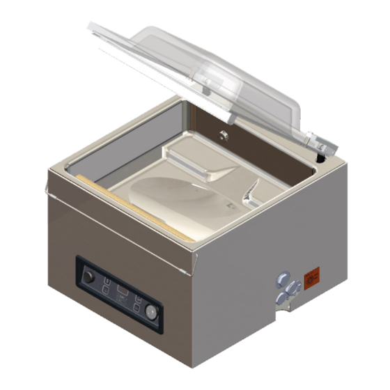
Description of the Machine This section provides an overview of the main components and functions. If detailed information is available in this manual, you will be referred to the specific sections. Overview of the Main Components The figure below shows the main components of the system. The model shown may differ from your machine. -
Page 12: Description Of The Packaging Process/Machine Functions
Vacuum pump The vacuum pump creates the vacuum. Power connection and cable This serves to connect the machine to the power supply. Description of the Packaging Process/Machine Functions This section provides an overview of the packaging process and available machine functions. See Changing the Program Settings on page 20 for information about setting the parameters to the correct values. -
Page 13: General Functions
4.2.2 General Functions Function Pictogram Operation Cleaning of the The pump cleaning program ensures that the pump is thoroughly oil pump rinsed. During the program, the pump and oil reach the operating temperature, so the oil and moisture are separated and any contamination is filtered. -
Page 14: Vacuum Pump
Consult Replacing the Sealing Wire on page 27 for more detailed information about maintenance. Silicone holder Opposite the sealing bar is a silicone holder which provides counterpressure on the cylinders (Replacing the Silicone Rubber of the Silicone Holders on page 29). Sealing mechanism The sealing bars are pressed onto the vacuum bag by cylinders. -
Page 15: Electrical Installation
Figure 5: Overview of the Pump (Pump 16 m Vacuum pump - Creates the vacuum for the process. Oil exhaust filter - Filters the air by capturing oil vapours. Oil sight glass - Indicates the maximum and minimum oil levels of the vacuum pump. Oil drain plug - Removing the oil drain plug allows the oil to be drained. -
Page 16: Figure 6: Overview Of The Electrical Installation
The machine consists of the following electrical components: Figure 6: Overview of the Electrical Installation Power connection and cable This serves to connect the machine to the power supply. Control panel This serves to operate the control functions. Your machine has the following control option: •... -
Page 17: Installation
Installation Consult Technical Data on page 35 for the specifications of the machine. Before installing the machine, carefully read the safety instructions in Safety on page 7. Failure to follow or disregard of the safety instructions may result in serious injury. Transportation and Installation The machine must be moved and transported in an upright position. -
Page 18: Operation
Operation It is possible to optimise a program for your products by modifying the parameters of a program, see Changing the Program Settings on page 20. • All persons responsible for the operation of this machine must at least fully read and understand the chapters Safety on page 7 and Operation on page 18. -
Page 19: Starting The Machine
Function display The LED light in front of the function lights up if the function is active during the program cycle or if the function is selected in the programming mode. – / STOP button This is used to interrupt the entire cycle during a packaging cycle. All functions are skipped and the cycle is terminated. -
Page 20: Terminating A Program
Terminating a Program Programs such as the packaging program or the pump cleaning program can be terminated at any time. Terminate the program. Press the – / STOP button. The program will be terminated and the vacuum chamber is decompressed. Changing the Program Settings 6.6.1 1-Program Control System... -
Page 21: Guideline For Function Values
Check in advance whether the relevant food container can withstand and hold a vacuum. To select the External Vacuum option, follow the steps below. Select the External Vacuum program. Press the Pump Cleaning Program button. The display will show "C". Press the Cursor key. -
Page 22: Figure 9: Vapour Pressure Curve Of Water
Function Range Conditions The average seal time is 1.8-2.5 seconds. Cleaning of the 15 minutes Fixed value. pump The vacuum in the chamber must be at least 30% at the moment of sealing (0.7 bar on the meter). If the pressure is reduced, the boiling point of liquids will be decreased; see Figure 9: Vapour Pressure Curve of Water on page 22. -
Page 23: Maintenance
Maintenance When carrying out maintenance work, always observe the following safety rules. • Only trained technicians are authorised to perform the described maintenance activities. • Always disconnect the power supply by disconnecting the plug. • Test the machine after carrying out maintenance work or repairs to make sure the machine can be used safely. -
Page 24: Cleaning The Machine
Activity * 1-D 1-W 6-M 1-Y 4-Y Replace the plastic lid. * 1-D = Daily, 1-W = Weekly, 6-M = Every 6 months, 1-Y = Annually, 4-Y = Every 4 years Cleaning the Machine Never clean the machine using a high pressure cleaner. Do not use any aggressive or toxic cleaning agents. -
Page 25: Replacing The Oil Exhaust Filter
Place a drip pan under the oil drain plug. Remove the oil drain plug. The oil will drain from the pump. Replace the oil drain plug. Follow the steps below to add oil to the pump. You can follow these steps after all oil has been removed, but also to refill oil. -
Page 26: Pump 8 M
Make sure the O-ring is properly placed on the filter inlet. 7.5.2 Pump 8 m Figure 11: Replacing the Oil Exhaust Filter (Pump 8 m Follow the steps below to remove the old oil exhaust filter: Remove the filter cover (3) of the vacuum pump (1) and put it aside. Remove the oil exhaust filter (2) from the vacuum pump. -
Page 27: Pump 16 M
7.5.3 Pump 16 m Figure 12: Replacing the Oil Exhaust Filter (Pump 16 m Follow the steps below to remove the old oil exhaust filter: Remove the filter cover (4) of the vacuum pump (1) and put it aside. Remove the leaf spring (3) and put it aside. Remove the old filter (2). -
Page 28: Figure 13: Removing The Sealing Bar
Figure 13: Removing the Sealing Bar Remove the sealing bar by lifting it from the cylinders. See Figure 13: Removing the Sealing Bar on page 28. Figure 14: Replacing the Sealing Wire Remove the Teflon tape (1) that protects the sealing wire. Remove the screws (2) at the bottom of the sealing bar and remove the sealing wires (3). -
Page 29: Replacing The Silicone Rubber Of The Silicone Holders
Place the other end of the wire in its location and tension it with pliers. Now fasten it by tightening the screws. Cut both ends of the wire. Replace the Teflon tape on the sealing wire. Cut a piece of Teflon tape at the length of the sealing bar plus approximately 5 cm. Attach the tape over the sealing wires on the sealing bar evenly and without folds. -
Page 30: Replacing The Lid Gasket
Replacing the Lid Gasket The lid gasket ensures the vacuum chamber is fully closed during the machine cycle. This is essential to reach the maximum vacuum level. Due to extreme pressure differences, the gasket wears and should therefore be replaced regularly. Replace the lid gasket if damaged or as specified in Maintenance Schedule on page 23. -
Page 31: Troubleshooting
Troubleshooting The tables below show the possible malfunctions and the corresponding causes as well as the steps to be taken. Malfunction Activity More information Control panel does not • Connect the machine to the Electrical Installation on page illuminate. power supply. The control panel is on, but •... - Page 32 Malfunction Activity More information The lid does not open • Check the gas spring/ Contact your supplier. automatically. springs of the lid. Error messages for the 1-program control system Malfunction Activity More information "F1" in display. • Check or adjust the switch of Contact your supplier.
-
Page 33: Terms Of Warranty
The warranty is subject to the following limitations. The warranty period for products supplied by Henkelman BV is 3 years from the date indicated on the purchase document. This warranty is limited to manufacturing and machining defects and therefore does not cover breakdowns involving any part of the product that is exposed to any form of wear and tear. -
Page 34: Disposal
Disposal Do not dispose of oil and components as household waste. When replacing oil or components at the end of the service life, ensure that all materials are collected and disposed or reused in a legal and environmentally sound manner. Disposal... -
Page 35: Appendices
Appendices 11.1 Technical Data 11.1.1 Technical Data Jumbo Jumbo Mini Jumbo Jumbo Plus General Ambient temperature during operation 5 to 30°C 5 to 30°C 5 to 30°C Sound emission < 70 dB(A) < 70 dB(A) < 70 dB(A) Maximum daily production... - Page 36 Jumbo 42XL General Ambient temperature during operation 5 to 30°C 5 to 30°C 5 to 30°C Sound emission < 70 dB(A) < 70 dB(A) < 70 dB(A) Maximum daily production 5 hrs/day 5 hrs/day 5 hrs/day Dimensions of the machine...
-
Page 37: Logbook
11.2 Logbook This logbook must include: • Annual maintenance work • Major replacements and emergencies • Modifications • Tests of the emergency stop buttons and safety devices Date: Performed by: Description: (authority, technician) (nature of the activities, which parts have been replaced) Appendices... - Page 38 Date: Performed by: Description: (authority, technician) (nature of the activities, which parts have been replaced) Appendices...
-
Page 39: Ec Declaration Of Conformity
Titaniumlaan 10 5221 CK, "s-Hertogenbosch The Netherlands declare under our sole responsibility that the product; • Machine type: Jumbo series complies with all relevant provisions of the Directives; • 2006/42/EC: Machinery Directive • 2014/30/EG: EMC Directive • 2014/35/EC: Low Voltage Directive The undersigned is authorised to compile the technical file. - Page 40 Henkelman BV Titaniumlaan 10 5221 CK "s-Hertogenbosch +31 (0)73 621 3671 +31 (0)73 622 1318 www.henkelman.com info@henkelman.com...
Need help?
Do you have a question about the Jumbo and is the answer not in the manual?
Questions and answers