
Subscribe to Our Youtube Channel
Related Manuals for EAS Electric ECM Series


Summary of Contents for EAS Electric ECM Series
- Page 1 AIRE ACONDICIONADO CASSETTE CASSETTE-TYPE AIR CONDITIONING Cassette compacto Compact cassette Serie ECM MANUAL DE INSTRUCCIONES OWNER AND INSTALLATION MANUAL...
- Page 2 Tabla de contenido Manual de usuario Precauciones de seguridad ............ 04 LA SEGURIDAD ES LO PRIMERO Piezas de la unidad interior y Funciones Principales ........... Funcionamiento manual ............
-
Page 3: Table Of Contents
Cuidado y mantenimiento ......08 a. Unidad de mantenimiento ......08 b. Cómo limpiar el filtro de aire ....c. Reparación de fugas de refrigerante ..d. Preparación para períodos de no uso ..Solución de problemas ......... a. Problemas comunes ........10 b. -
Page 4: Precauciones De Seguridad
Precauciones de seguridad Gracias por adquirir este aparato de aire acondicionado que. Este manual le proporcionará la información sobre la forma de operar, mantener y solucionar problemas de su acondicionador de aire. Siguiendo las instrucciones que se asegurará el buen funcionamiento y prolongar la vida útil de la unidad. -
Page 5: Condiciones De Operación
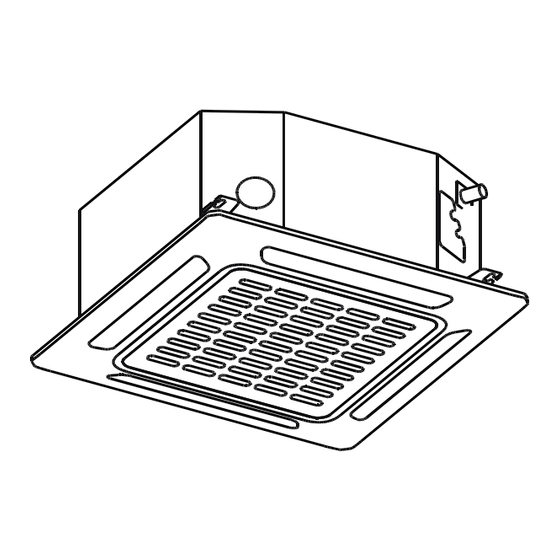
Piezas de la unidad interior y funciones principales Piezas de la unidad Panel de visualización Lama Salida de aire Entrada de aire Fig. 2.1 Condiciones de operación Utilice el sistema en la siguiente temperatura para un funcionamiento seguro y eficaz. Si se utiliza el acondicionador de aire fuera de las siguientes condiciones, puede fallas de funcionamiento o menos eficiente. -
Page 6: Consejos Para Ahorrar Energía
Características Configuración predeterminada Rejilla Ángulo función de memoria (opcional) Cuando se reinicia el acondicionador de aire Algunos modelos están diseñados con una función después de un fallo de alimentación, se pondrá de memoria ángulo de las aletas. Cuando la unidad por defecto a los ajustes de fábrica (modo se reinicia después de un fallo de alimentación, el AUTO, ventilador AUTO, 24 °... -
Page 7: Funcionamiento Manual
Funcionamiento manual Este panel de visualización de la unidad interior se puede utilizar para hacer funcionar la unidad en caso de que el control remoto se ha perdido o está fuera de baterías. Botón manual Receptor infrarrojo infrarrojos Indicador de alarma Indicador de funcionamiento Indicador de tiempo PRE-DEF... -
Page 8: Cuidado Y Mantenimiento
Cuidado y mantenimiento ADVERTENCIA:NO ELIMINAR O Precauciones de seguridad LIMPIAR EL FILTRO POR SÍ MISMO Póngase en contacto con un técnico de servicio • autorizado para su reparación o mantenimiento de Cómo quitar y limpiar el filtro puede ser peligroso. esta unidad. -
Page 9: Reparación De Fugas De Refrigerante
Reparación de fugas de refrigerante 4. Retire el filtro de aire. 5. Limpiar el filtro de aire con la aspiradora de ADVERTENCIA la superficie o el lavado en agua caliente con un detergente suave. Si las fugas de refrigerante, apague el aire •... -
Page 10: Solución De Problemas
Solución de problemas PRECAUCIONES Si se produce una de las siguientes condiciones, apague la fuente de alimentación inmediatamente y póngase en contacto con su distribuidor para obtener más ayuda. La luz operación continúa a parpadear rápidamente después de que la unidad se ha reiniciado. •... -
Page 11: Consejos Para Solucionar Problemas
Problema Posibles causas El polvo se emite desde La unidad puede acumular polvo durante períodos prolongados de no uso, que se emiten la unidad interior o cuando la unidad está encendida. Esto se puede mitigar, cubriendo la unidad durante exterior largos períodos de inactividad. -
Page 12: Códigos De Error
Códigos de error Núm. destellos Código Indicador de Causa Número por segundo tiempo error EEPROM interior de error (eléctricamente programable Apagado y borrable memoria de sólo lectura) Interiores y exteriores de un mal funcionamiento de Apagado comunicación de unidad Mal funcionamiento de la velocidad del ventilador interior Apagado Error del sensor de temperatura interior de la habitación Apagado... -
Page 13: Directrices Europeas Relativas A La Eliminación
Directrices europeas relativas a la eliminación Los usuarios de los países europeos pueden estar obligados a desechar adecuadamente esta unidad. Este aparato contiene refrigerante y otros materiales potencialmente peligrosos. Al deshacerse de este aparato, la ley requiere la recolección y tratamiento especial. NO deseche este producto como residuo doméstico o basura municipal sin clasificar. - Page 14 Conexion placa electronica modelo 71: 16022500004023 NOTE: Inner Driver WIRING DIAGRAM Anti-cold air The wiring diagram DC Motor TO WIRE NEWFAN Alarm Remote SWITCH (INDOOR UNIT) is for explanation POWER REQUEST. CONTROLLER Output Control purpose only. The FAN MOTOR STOP-TEM FUNCTION OF SWITCH ...
-
Page 15: Exclusiones De La Garantía
CONDICIONES DE LA GARANTÍA COMERCIAL Este producto tiene una garantía de reparación de dos años a partir de la fecha de venta, contra todo defecto de funcionamiento proveniente de la fabricación, incluyendo mano de obra y piezas de recambio, y cinco años de garantía en el compresor (solo componente). - Page 16 Daños en fusibles, lamas, focos, flujostato de caudal, filtros y otros elementos derivados del desgaste normal debido a la operación del equipo. Las averías que tengan su origen o sean consecuencia directa o indirecta de: contacto con líquidos, productos químicos y otras sustancias, así como de condiciones derivadas clima...
- Page 17 Table of Contents Owner’s Manual Safety Precautions ............ SAFETY FIRST Indoor Unit Parts and Major Functions ..Manual Operation ............
- Page 18 Care and Maintenance ......a. Unit Maintenance ........b. How to Clean the Air Filter......c. Repairing Refrigerant Leaks ....d. Preparation for Periods of Non-use ..Troubleshooting ......... a. Common Problems ......b. Troubleshooting Tips ......European Disposal Guidelines ..............
- Page 19 Safety Precautions Thank you for purchasing this air conditioner. This manual will provide you with information on how to operate, maintain, and troubleshoot your air conditioner. Following the instructions will ensure the proper function and extended lifespan of your unit. Please pay attention to the following signs: Failure to observe a warning may result in serious injuries.
-
Page 20: Indoor Unit Parts And Major Functions
Indoor Unit Parts And Major Functions Unit Parts Display panel Louver Air outlet Air inlet Fig. 2.1 Operating Conditions Use the system in the following temperature for safe and effective operation. If the air conditioner is used outside of the following conditions, it may malfunction or be less efficient. - Page 21 Features Default Setting Louver Angle Memory Function (Optional) When the air conditioner restarts after a power Some models are designed with a louver angle failure, it will default to the factory settings memory function. When the unit restarts after a (AUTO mode, AUTO fan, 24°C (76°F)).
-
Page 22: Manual Operations
Manual Operations This display panel on the indoor unit can be used to operate the unit in case the remote control has been misplaced or is out of batteries. Manual button Infrared receiver tion indicator Opera Alarm indicator Timer indicator PRE-DEF (pre-heating/defrost) -
Page 23: Care And Maintenance
Care And Maintenance WARNING: DO NOT REMOVE OR Safety Precautions CLEAN THE FILTER BY YOURSELF Contact an authorized service technician for • repair or maintenance of this unit. Improper Removing and cleaning the filter can be repair and maintenance may cause water dangerous. -
Page 24: Repairing Refrigerant Leaks
Repairing Refrigerant Leaks 4. Remove the air filter. 5. Clean the air filter by vacuuming the surface WARNING or washing it in warm water with mild detergent. If the refrigerant leaks, turn off the air • A. If using a vacuum cleaner, the inlet side conditioner and any combustible heating should face the vacuum. -
Page 25: Troubleshooting
Troubleshooting CAUTIONS If one of the following conditions occurs, switch off the power supply immediately and contact your dealer for further assistance. The operation light continues to flash rapidly after the unit has been restarted. • The remote control buttons do not work. •... -
Page 26: Troubleshooting Tips
Problem Possible Causes Dust is emitted from The unit may accumulate dust during extended periods of non-use, which either the indoor or will be emitted when the unit is turned on. This can be mitigated by covering outdoor unit the unit during long periods of inactivity. The unit may absorb odors from the environment (such as furniture, cooking, The unit emits a cigarettes, etc.) which will be emitted during operations. -
Page 27: Error Codes
Error Codes The number Error Timer of flashes Number Cause Code indicator per second Indoor EEPROM (Electrically Erasable Programmable Read-Only Memory) error Indoor and outdoor unit communication malfunction Indoor fan speed malfunction Indoor room temperature sensor error Evaporator coil temperature sensor error Refrigerant leak detection system malfunction Water level alarm malfunction Dual indoor unit (twin model only) -
Page 28: European Disposal Guidelines
European Disposal Guidelines Users in European Countries may be required to properly dispose of this unit. This appliance contains refrigerant and other potentially hazardous materials. When disposing of this appliance, the law requires special collection and treatment. DO NOT dispose of this product as household waste or unsorted municipal waste. -
Page 29: Exclusions From The Guarantee
COMMERCIAL GUARANTEE CONDITIONS FOR AIR CONDITIONING This product has a two-year repair guarantee from the date of sale, against all manufacturing malfunctions, including repairwork and replacement parts, and a five-year guarantee on the compressor (component only). To justify the purchase date, it will be mandatory to present the end user's invoice or purchase receipt and the installation company data. - Page 30 15. Damage to fuses, blades, lamps, flow switch, filters and other elements derived from normal wear and tear due to the operation of the equipment. 16. Faults that have their origin or are a direct or indirect consequence of: contact with liquids, chemicals and other substances, as well as conditions derived from the climate or the environment: earthquakes, fires, floods, excessive heat or any other external force , such as insects, rodents and other animals that may have access to...
- Page 31 ;$'-,(! !"#$%#&!'(!-$*+#&#,-.$! "##$%&'(&%! $$$$$$$$$$$$$$$$$$$$$$$$$$$$$$$$$$$$$$$$$$$$$$$$$$$$$$$$$$$"%&" )'$#*+#(&,$%!-$!%$.+'(-*-! $$$$$$$$$$$$$$$$$$$$$$"%'" )'&#$%&!-$!(,%/*0*#(1,! <! $$$$$$$$$$$$$$$$$$$$$$$$$$$$$$$"%(" " " " " " " !4!2,%/*0*#(1,!-$!0*!+,(-*-!(,/$'(&'! $$$$$$$$$$$$$$$$$$$%@" " " A2=?2+3+-3,"43"65"/+1454"1+-3.12." " $$$$$$$$$$$$$$$$$$$$$$$$%@" *+,-./0012+3,"?5.5"65"1+,-565017+"43"65"/+1454"" *+-3.12.""$$$$$$$$$$$$$$$$$$$$$$$$$$$$$$$$$$$$$$$$$$$$$$$$$$$$$$$$$$$$$$$$" %" " " " " " 2,%/*0*#(1,!-$!0*!+,(-*-!$3/$'(&'! $$$$$$$$$$$!)" *+,-./0012+3,"43"1+,-565017+"43"65"/+1454" 38-3.12." $$$$$$$$$$$$$$$$$$$$$$$$$$$$$$$$$$$$$$$$$$$$$$$$$$$$$$$$$$$$$$$$$$$$$!)" *+,-565017+"436"-/92"43"43,5:;3" $$$$$$$$$$$$$$$$$$$$$$$!&" <2-5,",29.3"07=2"-5654.5."2.1>1012,"3+"65" ?5.34" $$$$$$$$$$$$$$$$$$$$$$$$$$$$$$$$$$$$$$$$$$$$$$$$$$$$$$$$$$$$$$$$$$$$$$$$$!&" "...
- Page 32 " " " !@@@@@@@@@@@@@@@@@@@@! >&,$3(.,!-$!0*!/+5$'3*!-$!'$?'(.$'*,/$ !B" CD1,2",29.3"65"62+:1-/4"E"363D5017+"43"65"-/93.F5"$" B" *+,-./0012+3,"?5.5"65"02+3817+"43"65"-/93.F5"43"" G3>.1:3.5+-3HHHHHHHHHHHHHHHHHHHH$ $$$"!(" *+,-565017+"436"5=2.-1:/542. $$$$$$$$$$$$$$$$$$$$$$$$$$$$$$$$$$$$$$$#%" I" <" >*50$*-& $$$$$$$$$$$$$$$$$$$$$$$$$$$$$$$$$$$$$$$$$$$$$$$$$" ##" J.305/012+3,"43",3:/.1454"$$$$$$$$$$$$$$" #" A5963542"43"65"/+1454"38-3.12." $ $$$$$$$" ##" A5963542"43"65"/+1454"1+-3.12."$$$$$$$$" #)" " " " " LA" LA" AB*#+*#(1,!-$0!*('$ $$$$$$$$$$$$$$$$$$$$$$$$$$$$$$$$$$$$$$$$$$$$$$$$$$" #&" *+,-./0012+3,"43"3D50/5017+" $$$$$$$$$$$$$$$$$$$$$$$$$$$$$$$$$" #&" CD1,2",29.3"65"541017+"43".3>.1:3.5+-3"$$$$$$$$$$$$$" #'" "...
- Page 33 @,,(*10-1*! M,-3"3N/1?2"43"51.3"502+41012+542"1+06/E3"62,"5003,2.12,",1:/13+-3,$"O/.5+-3",/"1+,-565017+P"/-16103"65," ?13Q5,"E"5003,2.12,"N/3"1+06/E3"3,-3"3N/1?2$"R+5"1+,-565017+"1+02..30-5"?/343"45."6/:5."5"?S.4145,"43" 5:/5P"43,05.:5,"36S0-.105,P"1+03+412,"2"913+"?.2D205.">5662,"43">/+012+5=13+-2"3+"36"3N/1?2$" A14B0(! @5#0-($,-#! /#$+-'#'! )$*+#&#,-.$! *+,-565017+"43"65"?65+-1665"43" '(!&#!%$-'#'! ?5?36"T56:/+2,"=24362,U" !" -$+(0-10C! C1,65=13+-2"?5.5"-/93.F5"43" @,,(*10-1*! !" :5,"T56:/+2,"=24362,U" 0(D0->(0#,-.$! C1,65=13+-2"?5.5"-/93.F5"43" !" 6FN/142"T56:/+2,"=24362,U" G3D3,-1=13+-2"43"-/92"43" !" ,56145"T56:/+2,"=24362,U" J.3,1665"436"-/92"43",56145" @,,(*10-1*! !" T56:/+2,"=24362,U" '(!&#!+%B(03#! '(!'(*#>E(! V/+-5"43"43,5:;3"T56:/+2," !" =24362,U" C+1662"29-/.542."T56:/+2," !" =24362,U" W5+0X2"43"-30X2" &" @,,(*10-1*! J3.+2"43",/,?3+,17+" &"...
- Page 34 90(,#%,-1$(*!'(!*(>%0-'#'! 7(#!(&!#5#0+#'1!90(,#%,-1$(*!'(!K(>%0-'#'!#$+(*!'(!-$*+#�!(&!(L%-51C! K-!(&!(L%-51!*(!-$*+#&#!*-$!50(*+#0!#+($,-.$!#!&#*!50(*($+(*!-$*+0%,,-1$(*M!'-,N#!-$*+#&#,-.$!*(0O! -$,100(,+#!P!51'03#!1,#*-1$#0!'#Q1*!4#+(0-#&(*!P!5(0*1$#&(*!>0#R(*C! I5":.5D3454"43"62,"?2,1963,"45^2,"=5-3.1563,"E"?3.,2+563,",3"43-3.=1+5"02+"62,"1+410542.3,"@S2:=8):A/)@!2" @8:A/)KA$! M6"1+0/=?61=13+-2"43"65,"54D3.-3+015,".3561Q545,"3+"36"?.3,3+-3"=5+/56"?/343"?.24/01." 63,12+3,$"M,-2,"41,?2,1-1D2,"4393.[+"1+,-565.,3",1:/13+42"65"+2.=5-1D5"+5012+56"56".3,?30-2$" @S2:=8:A/)@! M6"1+0/=?61=13+-2"43"65,"?.305/012+3,"43,0.1-5,"3+"36"?.3,3+-3"=5+/56"?/343"205,12+5." 45^2,"?3.,2+563,"2"45^2,"3+"36"3N/1?2$" @8:A/)KA! !"#$"%$#&#'(#)*$+'",#-,.*/"0$)"$1"2-'.)#)$#/("0$)"$./0(#%#'$"%$"3-.&*4 @S2:=8:A/)@! J M+"013.-2,"3+-2.+2,"43">/+012+5=13+-2P"02=2"0201+5,P",565"43",3.D142.3,P"3-0$P",3 !#0$*&"'#,.*/"0$)"$./0(#%#,.5/6$7#/("/.7."/(*$8$'"&#'#,.5/$)"$"0("$"3-.&*$)"$#.'" .302=13+45"3+05.30145=3+-3"36"/,2"43"3N/1?2,"43"51.3"502+41012+542"3,?301563,$ #,*/).,.*/#)*$%#0$)"9"':$%%";#'$#$,#9*$-/$(<,/.,*$#-(*'.=#)*4 M6"43,3=?3^2"1+02..30-2"43"65,"-5.35,"43"1+,-565017+"?/343"?.2D205.",50/4145,"36S0-.105,P 1.2#$#%$&."$)"$%#$%"('#$%#0$./0('-,,.*/"0$)"$./0(#%#,.5/$&'";.0(#0$"/$"%$&'"0"/("$7#/-#%4 02.-201.0/1-2,P">/:5,P"1+03+412,"E"2-.2"-1?2"43"45^2,"56"3N/1?2P"5,F"02=2"45^2,"?3.,2+563,$ M6"43,3=?3^2"1+02..30-2"43"65,"-5.35,"43"1+,-565017+"?/343"?.2D205.",50/4145,"36S0-.105,P 02.-201.0/1-2,P">/:5,P"1+03+412,"E"2-.2"-1?2"43"45^2,"56"3N/1?2$ _ A2+30-3"3+"36"05963542">1]2"/+",30012+542."/+1D3.,56"?5.5"-242,"62,"?262,"43]5+42"/+5",3?5.5017+ 43")=="3+-.3"62,"=1,=2,`"1+02.?2.3"3+"65"1+,-565017+">1]5"/+"41,?2,1-1D2"43"02..13+-3".3,14/56 TGAOU"43"=[,"43"!%"=CP"?3.2"N/3"+2",/?3.3"65,")%"=CP"N/3"0/=?65"02+"65"+2.=5-1D5"+5012+56"56 .3,?30-2$ _ C+-3,"43"663D5."5"0592"65"1+,-565017+"4393.["-3+3."3+"0/3+-5",1"65"Q2+5"3+"65"N/3",3"3+0/3+-.5"3, ?.2?3+,5"5"D13+-2,"X/.505+542,P"-1>2+3,"2"-3..3=2-2,$"O3"62"02+-.5.12P"36">/+012+5=13+-2"436 3N/1?2"?24.F5"D3.,3"5>30-542$ _ C6"50595."65"1+,-565017+P"02=?./393"N/3"+2"X5E">/:5,"43".3>.1:3.5+-3"E"N/3"65"/+1454">/+012+5 02..30-5=3+-3$"M6".3>.1:3.5+-3"3,"/+5",/,-5+015"-78105"3"1+>65=5963"E",/?2+3"/+":.5D3".13,:2 ?5.5"65",56/4"E"65",3:/.1454$ J M,-3"3N/1?2"3,"5?-2"?5.5"+1^2,"43"20X2"5^2,"3+"54365+-3P"?3.,2+5,"02+"05?501454">F,105P ,3+,2.156"2"=3+-56".34/0145P"2"913+"02+">56-5"43"38?3.13+015"E"02+201=13+-2P",13=?.3"E"0/5+42 ,35+",/?3.D1,542,"2"X5E5+".3019142"65,"02..3,?2+413+-3,"1+,-./0012+3,"?5.5"=5+3]5."3,-3 5?5.5-2"43"=5+3.5",3:/.5"E"3+-3+43."62,".13,:2,"N/3"1=?6105"36"/,2"43"3,-3$"C,3:a.3,3"43"N/3 62,"+1^2,"+2"]/3:/3+"02+"3,-3"5?5.5-2$"I2,"+1^2,"+2"4393+".3561Q5."65,"-5.35,"43"61=?13Q5"E...
- Page 35 @S2:=8:A/)@! J I5"43,02+3817+"436"41,?2,1-1D2"4393"1+02.?2.5."/+",30012+542."/+1D3.,56"?5.5"-242,"62,"?262,"3+ 36"05963542">1]2P"02+>2.=3"5"62"?.3D1,-2"3+"65"+2.=5-1D5"62056"56".3,?30-2$ J I5,"?3.,2+5,"N/3"=5+1?/65+"2".3?5.5+"01.0/1-2,"43".3>.1:3.5017+"4393+"3,-5."3+"?2,3,17+"43"/+ 03.-1>10542"D[6142"E"D1:3+-3"3=1-142"?2."/+5"5/-2.1454"02=?3-3+-3"N/3"50.341-3",/"02=?3-3+015 ?5.5"=5+1?/65.":5,3,".3>.1:3.5+-3,"43">2.=5",3:/.5P"02+>2.=3"5"62"?.3D1,-2"3+"65,"3,?301>105012+3, 43"3D56/5017+".302+20145,$ J I5,"-5.35,"43"=5+-3+1=13+-2",3"663D5.[+"5"0592"02+>2.=3"5"65,"3,?301>105012+3,"436">59.105+-3$ I5,"-5.35,"43"=5+-3+1=13+-2"E".3?5.5017+"N/3".3N/13.5+"65"5E/45"43"?3.,2+56"0/561>10542",3 663D5.[+"5"0592"95]2"65",/?3.D1,17+"43"/+5"?3.,2+5"3,?301561Q545"3+"36"=5+3]2"43":5,3, .3>.1:3.5+-3,"1+>65=5963,$ J *+,-563"36"3N/1?2"3+"Q2+5,"42+43"+2"?/345+"?.24/01.,3"45^2,"=30[+102,$ J L5+-3+:5"65,"593.-/.5,"619.3,"43"29,-[0/62,$ @2)KH<!I5"1+>2.=5017+",1:/13+-3"3,"2961:5-2.15"?5.5"65,"/+14543,"02+".3>.1:3.5+-3"-1?2"G)#$ J *+,-563"36"3N/1?2"3+"/+5"Q2+5"563]545"43">/3+-3,"43"1:+1017+"50-1D5,"T02=2"?2."3]3=?62P 665=5,"5913.-5,P"/+"5?5.5-2"43":5,"2"/+"0563+-542."36S0-.102U$ J <2"?3.>2.3"+1"N/3=3$ J G3D1,3"36".3>.1:3.5+-3"E"02=?./393"N/3"+2"?.2D205"262.3,$ J I5"+2.=5-1D5"+5012+56",29.3"65"=5+1?/65017+"43":5,3,"4393.[".3,?3-5.,3"3+"-242"=2=3+-2$ J *+,-563"36"3N/1?2"3+"/+5"Q2+5"913+"D3+-16545"0/E5,"41=3+,12+3,"021+0145+"02+"65,"41=3+,12+3,"43 [.35"3,?30F>105,"43">/+012+5=13+-2$ J M6"3N/1?2",3"4393.["1+,-565.P"=5+3]5."E"56=503+5."3+"/+5"3,-5+015"02+"/+5",/?3.>1013",/?3.12. 5"b"= `"65,"-/93.F5,"4393+"20/?5."/+5",/?3.>1013"=F+1=5"43"b"= "T02+,/6-3"65"-5965",1:/13+-3U$ M6"3N/1?2"+2"4393"1+,-565.,3"3+"Q2+5,",1+"D3+-165017+"0/E5",/?3.>1013",35"1+>3.12."5"b"= T02+,/6-3"65"-5965",1:/13+-3U$"I5"-/93.F5"43".3>.1:3.5+-3"4393.["1+,-565.,3"3+"65,"Q2+5, 02+-3=?6545,"?2."65"+2.=5-1D5"62056",29.3"1+,-565012+3,"43":5,$ "1'(&1! /#0>#!'(!0(D0->(0#$+(! K%5(0D-,-(! @&+%0#!4LX-4#!'(!
- Page 36 @R-*1!*1B0(!&1*!>#*(*!D&%10#'1*! !$ M,-3"3N/1?2"43"51.3"502+41012+542"02+-13+3":5,3,">6/2.542,$"J5.5"=[,"1+>2.=5017+",29.3"36"-1?2"E 65"05+-1454"43":5,"N/3"02+-13+3"3,-3"?.24/0-2P"02+,/6-3"65"3-1N/3-5"54X3.145"56"=1,=2$ #$ I5,"2?3.5012+3,"43"1+,-565017+P"=5+-3+1=13+-2"E".3?5.5017+"65,"4393.["663D5."5"0592"/+"-S0+102 5/-2.1Q542$ )$ I5,"2?3.5012+3,"43"43,1+,-565017+"E".30106542"65,"4393.["663D5."5"0592"/+"-S0+102"03.-1>10542$ &$ \1"36"3N/1?2"0/3+-5"02+"/+",1,-3=5"43"43-30017+"43">/:5,",3"4393.[",2=3-3."5".3D1,17+"0545"!# =3,3,$ '$ G302=3+45=2,"3+05.30145=3+-3"663D5."/+".3:1,-.2"43"-245,"65,".3D1,12+3,"N/3",3".356103+"56"3N/1?2 3+"9/,05"43"?2,1963,">/:5,$ S(*,0-5,-1$!'(!&1*!*64B1&1*!'(!&#!%$-'#'!-$+(0-10!P!'(!&#!%$-'#'!(X+(0-10! F*1&1!5#0#!%$-'#'(*!,1$!0(D0->(0#$+(!+-51!=ZTG<! M,-3" ,F=9262" 1+4105" N/3" 36" 5?5.5-2" /-161Q5" /+" -1?2" 43" :5," .3>.1:3.5+-3" 1+>65=5963$" \1" ,3" ?.24/03" /+5" >/:5" 43" .3>.1:3.5+-3" E" 3,-3" 3+-.5" 3+" @S2:=8:A/)@! 02+-50-2"...
- Page 37 901,(*1!'(!-$*+#&#,-.$! H=S:A!S:!7@!)AK8@7@/)[A! )$*+#&(!&#!%$-'#'! )$*+#&(!&#!%$-'#'! )$*+#&(!&#!+%B(06#!'(! -$+(0-10!F5L>-$#!\G! (X+(0-10!F5L>-$#!IIG! '(*#>7(!F5L>-$#!IZG! I" <" LA" LA" /1$(,+(!&1*!+%B1*!'(!0(D0->(0#$+(! :R#,M(!(&!*-*+(4#!'(! /1$(,+(!&1*!,#B&(*! F5L>-$#!T]G! F5L>-$#!I^G! 0(D0->(0#,-1$! F5L>-$#!TTG! )$*+#&(!(&!5#$(&!D01$+#&! =(#&-,(!%$#!50%(B#!'(! F5L>-$#!T_G! D%$,-1$#4-($+1!F5L>-$#!T`G! ("...
- Page 38 )$*+#&#,-.$!'(!&#!%$-'#'!-$+(0-10! /1451$($+(*!'(!&#!%$-'#'!-$+(0-10! f2=95"43"43,5:;3"T43+-.2"43"65" /+1454"1+-3.12.U" g/92"43"43,5:;3" \56145"43"51.3" I5=5,"43"41.30017+"436"51.3" M+-.545"43"51.3" J5+-5665"43"1+>2.=5017+" G3]1665">.2+-56" g/93.F5"43".3>.1:3.5+-3" b->C!_CI! !90(,#%,-1$(*!'(!*(>%0-'#'! @S2:=8:A/)@! @8:A/)KA! _ *+,-563"36"3N/1?2"3+"/+5",/?3.>1013">1.=3 _ *+,-563"65"/+1454"1+-3.12.P"65"/+1454"38-3.12. N/3"?/345"5:/5+-5.",/"?3,2$"\1"65 E"62,"05963,"5"/+5"41,-5+015"=F+1=5"43"!"= 3,-./0-/.5"3,"43=5,1542"4S916P"3,"?2,1963 T)P#hU"43"-363D1,2.3,"E"3N/1?2,"43".5412"?5.5 N/3"65"/+1454",3"051:5"E"?.2D2N/3"45^2, 3D1-5."?.2963=5,"43"3,-[-105"2"41,-2.,12+3, ?3.,2+563,P"45^2,"=5-3.1563,"2"63,12+3, 3+"65"1=5:3+$"O3?3+413+42"436"-1?2"43 :.5D3,$ 3N/1?2,P"3,"?2,1963"N/3"!"="T)P#hU"43 41,-5+015"+2",35",/>1013+-3$ _ I5"/+1454"1+-3.12."4393"N/345."5"#P'= T(hUP"2"=[,P"436",/362$ _ \1"1+,-565"65"/+1454"1+-3.12.",29.3"/+5 AH!1+,-563"65"/+1454"1+-3.12."3+"95^2,"2"3+ ,/?3.>1013"43"=3-56"436"341>1012P",3.[ +303,5.12".3561Q5."/+5"02+3817+"5"-13..5$ 3,-5+015,"02+"65D542.5"E",30542.5P"E5"N/3"36 3803,2"43"X/=3454"43"3,-5,"Q2+5,"?24.F5+ ?.2D205."/+"02.-201.0/1-2"2"02..23."36 05963542$ @"...
- Page 39 !)$*+0%,,-1$(*!'(!-$*+#&#,-.$!'(!&#!%$-'#'! -"NAG>2KG! -$+(0-10! GO!1+,-563"65"/+1454"3+"65,",1:/13+-3,"Q2+5,Z" @2)KH<!I5"1+,-565017+"436"?5+36"4393.["663D5.,3"5" M+"Q2+5,"42+43",3"663D3"5"0592"38-.50017+"2" 0592"-.5,"X593."-3.=1+542"02+"62,"-.595]2,"43" >.50-/.5017+"?3-.263.5$" -/93.F5"E"43"05963542$" M+"Q2+5,"02,-3.5,"02+"/+"56-2"02+-3+142"43" ,56"3+"36"51.3$" 9#*1!I<!K(&(,,-1$!'(&!&%>#0!'(!-$*+#&#,-1$! M+"Q2+5,"42+43"36"51.3"?.3,3+-3"+1D363,"43" I5"/+1454"43"1+-3.12."4393"1+,-565.,3"3+"6/:5.3,"N/3" :5,3,"0[/,-102,P"02=2"?2."3]3=?62"03.05"43" 0/=?65+"02+"62,".3N/1,1-2,",1:/13+-3,Z" >/3+-3,"-3.=563,$" I5"/+1454"4393.["N/345."5"/+5"41,-5+015"=F+1=5"43 !"="T)@iU"43"65"?5.34"=[,"03.05+5$ M+"Q2+5,"02+">6/0-/5012+3,"43"?2-3+015P" ! M6"6/:5."3,02:142"4393"02+-5."02+"3,?5012",/>1013+-3 02=2">[9.105,$" ?5.5">50161-5."65,"-5.35,"43"1+,-565017+"E M+"3,?5012,"03..542,P"02=2"5.=5.12,$" =5+-3+1=13+-2$ M+"0201+5,"02+"1+,-565017+"43":5,"+5-/.56$" ! I5"Q2+5"43"1+,-565017+"4393"-3+3."3,?5012",/>1013+-3 M+"Q2+5,"38?/3,-5,"5">/3.-3,"2+45," ?5.5"?243."02+30-5."65,"-/93.F5,"E"36"-/92"43 3630-.2=5:+S-105,$" 43,5:;3$ M+"Q2+5,"3+"65,"N/3",3"56=503+3"=5-3.1563,"2" ! I5",/?3.>1013"436"-30X2"4393",3."X2.1Q2+-56"E",/ :5,3,"1+>65=5963,$" 3,-./0-/.5"4393"02+-5."02+"65".3,1,-3+015"+303,5.15 M+"3,-5+015,"02+"/+"56-2"+1D36"43"X/=3454P" ?5.5"5:/5+-5."36"?3,2"43"65"/+1454"1+-3.12.$ 02=2"95^2,"2"X591-5012+3,"02+"65D542.5"E"...
- Page 40 9#*1!T<!/%(&>%(!&#!%$-'#'!-$+(0-10! !$ R-16103"65"?65+-1665"43"?5?36"N/3"1+06/E3"36"3N/1?2"?5.5"02.-5."3+"36"-30X2"/+"2.1>1012".30-5+:/65.P 43]5+42"/+5"41,-5+015"43"56"=3+2,"!"="T)@iU"3+"-242,"62,"6542,$"I5,"41=3+,12+3,"436"2.1>1012",3.[+ 43"K%8K%"0="T#)$K8#)$KiU$"C,3:a.3,3"43"=5.05."3+"36"-30X2"65"Q2+5"42+43"D5"X503."36"2.1>1012$ I542"436"-/92"43"43,5:;3" I542"43"65"-/93.F5"43".3>.1:3.5+-3" e!="l")@i" e!="l")@i" '&'=="l"#!P'i"T?3.+2"43",/,?3+,17+U" e!="l")@i" 'B%=="l"##P&i"T3,-./0-/.5U" e!="l")@i" K&B=="l"#'$'i"T2.1>1012"-30X2U" b->C!_CZ! @8:A/)[A! M6"0/3.?2"43"65"/+1454"4393"N/345."?3.>30-5=3+-3" 561+3542"02+"36"2.1>1012$"C+-3,"43"02+-1+/5.P"5,3:a.3,3" 43"N/3"36"2.1>1012"43"65"/+1454"E"36"43"65"?5.34"-13+3+"36" =1,=2"-5=5^2$" #$ g5654.3"&"2.1>1012,"43"'"0="T#iU"43"?.2>/+41454"3+"65, Q2+5," 43,-1+545," 5" 1+,-565." 62," :5+0X2," 43" ,/]3017+ 436" -30X2$" C,3:a.3,3" 43" N/3" 65" .3]1665" N/345" 3+" /+ [+:/62"43"@%m"02+".3,?30-2"56"-30X2$ )$ A2+"...
- Page 41 '$ L2+-3"65"/+1454"1+-3.12.$"\3.[+"+303,5.15,"42, @2)KH<!A2=?./393"N/3"65"/+1454"1+-3.12."3,-[" ?3.,2+5,"?5.5"363D5."E",/]3-5."65"/+1454$ +1D36545$"I5"/+1454"1+02.?2.5"/+5"92=95"43" *+-.24/Q05"62,"?3.+2,"43",/,?3+,17+"3+"62, 43,5:;3"E"/+"1+-3../?-2."43"+1D36$"\1"65"/+1454"N/345" 2.1>1012,"43"?2,1017+"43"65"/+1454$"\/]S-362,"02+"65, 1+061+545"3+"41.30017+"02+-.5.15"56">6/]2"43" 02+43+,542"T3,"4301.P"65"-/93.F5"43"43,5:;3"3,-[" -/3.05,"E"5.5+4365,",/=1+1,-.545,"TD3."k1:$"&$'U$ 363D545UP"36"1+-3../?-2."43"+1D36"+2">/+012+5.[" 02..30-5=3+-3"E"?/343"45."6/:5."5">/:5,"43"5:/5$" <1D36"436"5:/5" b->C!_C\! b->C!_C^! @2)KH!9@=@!)AK8@7@/)HA:K! SH"PK8)/@K!Ac:2@K! @2)KH<!I5"?5.-3"1+>3.12."43"65"/+1454"4393.F5" M+"65,"1+,-565012+3,"42=S,-105,"+/3D5,",3"?/343" N/345."5"#&"=="T%$@iU"?2."3+01=5"43"65"?6505"436" 5?.2D30X5."?5.5"1+,-565."62,":5+0X2,"43"-30X2"3+" -30X2$"<2.=56=3+-3P"I"T02=2"1+4105"65"k1:$"&$KU" ?.1=3."6/:5.$"C,3:a.3,3"43"N/3"62,":5+0X2,"+2",3" 4393.[",3."65"=1-54"43"65"62+:1-/4"436"?3.+2"43" ,/36-3+"439142"5"65"02+-.50017+"436"X2.=1:7+$" ,/,?3+,17+"2"62",/>1013+-3=3+-3"65.:5"?5.5"3D1-5." O3,?/S,"43"1+,-565."36"0/3.?2"?.1+01?56"43"65" N/3"65,"-/3.05,",3",56:5+"43",/"?2,1017+$" /+1454P">1]3"65"?65+-1665"43"05.-7+"56"51.3" 502+41012+542"02+"?3.+2,"-1?2"LK8!#`"3,-2"63" L/.2" 5E/45.["5"43-3.=1+5."36"-5=5^2"E"65"?2,1017+"N/3" -3+4.["65"5?3.-/.5"436"-30X2$"J5.5"02+-1+/5."02+"36" .3,-2"43"65"1+,-565017+P",1:5"65,"1+,-./0012+3," 5+-3.12.3,$" A/3.?2"?.1+01?56" A/3.?2"?.1+01?56" I" """#&=="T%$@iU"" J6505"436"-30X2"...
- Page 42 )$*+#&#,-1$!'(!&#!%$-'#'!(X+(0-10! I5"Q2+5"4393"3,-5."619.3"43":5,3,"1+>65=5963,"E !)$*+0%,,-1$(*!'(!-$*+#&#,-.$!'(!&#!%$-'#'! 43"?.24/0-2,"N/F=102,$ (X+(0-10! I5"62+:1-/4"43"65"-/93.F5"N/3"02+30-5"65"/+1454 9#*1!I<!K(&(,,-1$!'(&!&%>#0!'(!-$*+#&#,-1$! 1+-3.12."02+"65"/+1454"38-3.12."+2"4393",/?3.5. I5"/+1454"1+-3.12."4393"1+,-565.,3"3+"6/:5.3,"N/3" 36"=[81=2"?3.=1-142$ 0/=?65+"02+"62,".3N/1,1-2,",1:/13+-3,Z" \1"3,"?2,1963P"AH!1+,-563"65"/+1454"3+"Q2+5, ! I5"/+1454"38-3.12."4393",1-/5.,3"62"=[,"03.05 38?/3,-5,"5"65"6/Q"41.30-5"436",26$ ?2,1963"43"65"/+1454"1+-3.12.$ ! \1"3,"?2,1963P"5,3:a.3,3"43"1+,-565."65"/+1454"43 ! M6"6/:5."3,02:142"4393"02+-5."02+"3,?5012 >2.=5"N/3"36"./142"+2"=263,-3"5",/,"D301+2,$ ,/>1013+-3"?5.5">50161-5."65,"-5.35,"43"1+,-565017+ \1"65"Q2+5"43"1+,-565017+"3,-["38?/3,-5"5">/3.-3, E"=5+-3+1=13+-2$ D13+-2,"T?2."3]3=?62P"03.05"43"65"02,-5UP ! I5"3+-.545"E",56145"43"51.3"+2"4393+ 0262N/3"65"/+1454"02+-.5"65"?5.34"?5.5"N/3 ! 3,-5."29,-./145,$ ! J.20/.3"N/3"65"/+1454"+2"N/345"38?/3,-5"5 N/343"?.2-3:145$"\1"3,"+303,5.12P"/-16103"/+5 D3+-1,05,"43"+13D3P"5"65"50/=/65017+"43"X2]5,"2 =5.N/3,1+5$"Tj3."k1:$"'$!"E"'$#U$ 5"2-.2"-1?2"43".3,-2,"3,-5012+563,$"\1"3,"?2,1963P A2+"36">1+"43"3D1-5."65"3,-[-105"2"1+-3.>3.3+015, 1+,-563"/+5"=5.N/3,1+5",29.3"65"/+1454"E 3+"65"1=5:3+"2"3+"36",2+142P"1+,-563"65, 5,3:a.3,3"43"N/3"+2",/?2+3"/+5"29,-./0017+ /+14543,"43"1+-3.12."E"43"38-3.12."E"62,"05963,P ?5.5"36"05/456"43"51.3$ 02=2"=F+1=2P"5"!"=3-.2"43"41,-5+015"43"62,...
- Page 43 !$ A262N/3"36"29-/.542."43"05/0X2"3+"36"38-.3=2"43"65 c$-'#'!(X+(0-10!+-51!K5&-+! ]/+-5"43"43,5:;3"N/3",3"D5"5"02+30-5."5"65"/+1454 TA2+,/6-3"65,"k1:$"'$&P"'$'"E"65"g5965"'$!U" 38-3.12.$ #$ *+-.24/Q05"65"]/+-5"43"43,5:;3"3+"36"2.1>1012",1-/542"3+ 65"95+43]5"1+>3.12."43"65"/+1454$ )$ W1.3"65"]/+-5"43"43,5:;3"@%m"X5,-5"N/3"21:5"/+"0610"E N/343"3+05]545"=1.5+42"5"65"?5.-3">.2+-56"43"65"/+1454$ Y" &$ A2+30-3"/+5"38-3+,17+"43"-/92"43"43,5:;3"T+2 b->C!^C_! 1+06/145U"5"65"]/+-5"43"43,5:;3"?5.5"D26D3."5"3+05/Q5. 36"5:/5"?.20343+-3"43"65"/+1454"0/5+42"36"=242 A563>50017+"3,-S"50-1D542$ \1"65"]/+-5"43"43,5:;3"+2"1+02.?2.5"/+"29-/.542."43 n" 05/0X2"TD3."k1:$"'$B"d"fUP"X5:5"62",1:/13+-3Z C" !$ *+-.24/Q05"65"]/+-5"43"43,5:;3"3+"36"2.1>1012",1-/542"3+ 65"95+43]5"1+>3.12."43"65"/+1454$"\3"21.["/+"0610 1+4105+42"N/3"65"]/+-5"43"43,5:;3"X5"N/34542"913+ O" f" 02620545$ b->C!^C^! #$ A2+30-3"/+5"38-3+,17+"43"-/92"43"43,5:;3"T+2 1+06/145U"5"65"]/+-5"43"43,5:;3"?5.5"D26D3."5"3+05/Q5. 36"5:/5"?.20343+-3"43"65"/+1454"0/5+42"36"=242 A563>50017+"3,-S"50-1D542$ 8#B&#!^CIC!:*5(,-D-,#,-1$(*!'(!&1$>-+%'!'(!&#! @2)KH<!C,3:a.3,3"43"N/3"36"5:/5"43"43,5:;3",3 %$-'#'!(X+(0-10!+-51!K5&-+!F%$-'#'<!44V-$GC! 43,05.:5"3+"/+5"Q2+5",3:/.5P"42+43"+2"05/,3"45^2,"+1 381,-5".13,:2"43".3,9565=13+-2$ S-4($*-1$(*!'(!&#!%$-'#'!(X+(0-10! S-4($*-1$(*!'(!41$+#f(!
- Page 44 )$*+#&#,-.$!'(!&#!+%B(03#!'(!'(*#>E(! I5"-/93.F5"43"43,5:;3",3"/-161Q5"?5.5"38?/6,5."56" AH8@!KHU=:!7@!)AK8@7@/)KA!S:!7@!8cU:=Q@! 38-3.12."36"5:/5"N/3",3"50/=/65"3+"65"/+1454$"R+5" S:!S:K@gR:! 1+,-565017+"1+02..30-5"?24.F5"205,12+5."45^2,"56" A/5+42"/-16103"/+"-/92">6381963"02+30-542"56"-/92"43 3N/1?2"E"45^2,"=5-3.1563,$" 43,5:;3P"5?.13-3"65"02+3817+"1+-3.+5"02+"/+"-/92 ?.2-30-2."541012+56"?5.5"3D1-5."N/3",3",/36-3"56"-1.5."43 @8:A/)KA! I5"-/93.F5"43"43,5:;3"4393.F5"-3+3."/+5"1+061+5017+ CF,63"-242,"62,"-/92,"?5.5"3D1-5."N/3",3"?.24/Q05 43,03+43+-3"43P"56"=3+2,P"!l!%%"?5.5"3D1-5."N/3"36 02+43+,5017+"E"36"5:/5"50593"45^5+42"65"/+1454$ 5:/5".3-2.+3"56"51.3"502+41012+542$ \1"65"-/93.F5"43"43,5:;3",3"02=95"2"1+,-565"43 J5.5"3D1-5."N/3"65"-/93.F5",3"02=93P"43]3"/+"3,?5012"43 >2.=5"1+02..30-5P"?/343+"?.24/01.,3"?S.4145,"43 5:/5"N/3"205,12+5.F5+"?.2963=5,"43 !d!P'="T&%d'@iU"3+-.3"62,"05963,">62-5+-3,$ >/+012+5=13+-2"3+"36"02+=/-542."43"+1D36"43"5:/5$ \1"65",56145"436"-/92"43"43,5:;3"N/345"=[,"56-5"N/3"65 A/5+42"36"=242"A563>50017+"3,-["50-1D542P"65 ]/+-5"43"65"92=95"436"0/3.?2P"0262N/3"/+"-/92"43 /+1454"43,05.:5"36"5:/5"N/3"?.24/03$"C,3:a.3,3"43 363D5017+"3+"65",56145"43"51.3"43"65"/+1454"1+-3.12.$"M6 N/3"36"-/92"43"43,5:;3"3,-["02+30-542"3+"65"Q2+5 -/92"43"363D5017+"+2"4393"1+,-565.,3"5"=[,"43"B'"0= 02..30-5"02+"36">1+"43"3D1-5."N/3"36"5:/5"43..5=545 T#@$'"qU"43"65"?6505"436"-30X2"E"65"41,-5+015"3+-.3"65 05/,3"45^2,"2"381,-5".13,:2"43".3,9565=13+-2 /+1454"E"36"410X2"-/92"43"363D5017+"4393",3."1+>3.12."5 439142"5",/"02+:365017+$ )%"0="T!!$(qU$ R+5"1+,-565017+"1+02..30-5"?/343"45."6/:5."5"N/3"36"5:/5" GO"-1.3"436"-/92"43"43,5:;3P"E5"N/3"?24.F5 >6/E5"43"+/3D2"X5015"36"1+-3.12."43"65"/+1454"E"65"1+/+43$ 43,02+30-5.,3"43"65"/+1454$ J5.5"3D1-5."65"5?5.1017+"43"9/.9/]5,"43"51.3P"=5+-3+:5 @2)KH!KHU=:!7@!/H"9=@!S:!8cUHK! 36"-/92"43"43,5:;3"+1D36542"2"61:3.5=3+-3"1+061+542 M,-5"1+,-565017+".3N/13.3"/+"-/92"43"?2613-163+2"...
- Page 45 R-16103"/+5"9.205"X/305"43"K'"=="T#$'iU"?5.5 -5654.5."/+"2.1>1012"3+"36"=/.2$"C,3:a.3,3"43 -5654.5."36"2.1>1012"02+"/+"[+:/62"61:3.5=3+-3 43,03+43+-3P"43">2.=5"N/3"36"38-.3=2 38-3.12."436"2.1>1012"N/343"/+2,"!#=="T%$'iU ?2."4395]2"436"38-.3=2"1+-3.12.$"M,-2">50161-5.[ 36"4.3+5]3"436"5:/5"TD3."k1:$"K$'U$"A262N/3"65 ?.2-30017+"3+"36"1+-3.12."436"2.1>1012$"O3"3,-5 >2.=5"?.2-3:3.["5=92,"38-.3=2,"436"2.1>1012"E ?3.=1-1.[",3665.62"0/5+42"50593"36"?.203,2"43 1+,-565017+$ L/.2" M8-3.12." *+-3.12." t"!#==" %$'"?/6:545," b->C!`C^! @2)KH<!A/5+42"-5654.3"36"2.1>1012"436"=/.2P"3D1-3" -.2?3Q5."02+"05963,P"363=3+-2,"43">2+-5+3.F5"E" 2-.2,"02=?2+3+-3,",3+,1963,$" *+-.24/Q05"36"-/92"43"43,5:;3"?2."36"2.1>1012"436 &$ =/.2$"C,3:a.3,3"43"N/3"36"5:/5"43"43,5:;3",3 43,05.:5"3+"/+5"Q2+5",3:/.5P"42+43"+2"05/,3 45^2,"+1"381,-5".13,:2"43".3,9565=13+-2$ @2)KH<!I5",56145"43"65"-/93.F5"43"43,5:;3" 4393.F5"3,-5.P"02=2"=F+1=2P"5"'"0="T!$@iU"436" ,/362$"\1"65"-/93.F5"-205"36",/362P"65"/+1454",3" 962N/35.["E"45.["?.2963=5,"43">/+012+5=13+-2$" \1"43,05.:5"36"5:/5"41.30-5=3+-3"5"65" 5605+-5.1665P"5,3:a.3,3"43"1+,-565."/+",1>7+"?5.5" 3D1-5."N/3"262.3,"43,5:.545963,",3"1+-.24/Q05+" 3+"65"D1D13+45$" !K"...
- Page 46 /1$(X-.$!'(!&#!+%B(03#!'(!0(D0->(0#$+(! !90(,#%,-1$(*!'(!*(>%0-'#'! !@R-*1!*1B0(!&#!&1$>-+%'!P!(&(R#,-1$!'(!&#!+%B(06#! C,3:a.3,3"43"N/3"65"62+:1-/4"43"65"-/93.F5"43" .3>.1:3.5+-3P"36"+a=3.2"43"0242,"E"65"05F45"3+-.3"65," @S2:=8:A/)@! /+14543,"1+-3.12."E"38-3.12."0/=?63+"62,".3N/1,1-2," _ I5"1+,-565017+"43"62,"-/92,"4393.["663D5.65 38?/3,-2,"3+"65"g5965"B$!Z" 5"0592"/+"-S0+102"?.2>3,12+56"E"0/=?61.[ 02+"65"+2.=5-1D5"62056"E"+5012+56"56 8#B&#!\CI<!71$>-+%'!P!,#3'#!4OX-4#*! .3,?30-2$ *(>h$!(&!41'(&1!F%$-'#'<!4VD+CG! _ A/5+42"1+,-563"36"3N/1?2"43"51.3 91+($,-#! 71$>-+%'! /#6'#!4LX-4#" "1'(&1" 502+41012+542"3+"3,-5+015,"?3N/3^5,P '(!&#! FU+%VNG" +%B(06#" -2=3"65,"=34145,"+303,5.15,"?5.5"3D1-5. r52" #'l(#" !%l)#P(" A2+D3.,17+"43" N/3"65"02+03+-.5017+"43".3>.1:3.5+-3 >.30/3+015"43"62," !52"d"r71" )%l@(P&" #%lK'PK" 380345"36"6F=1-3"43",3:/.1454"3+"05,2"43 =24362,"-1?2"\?61-" N/3",3"?.24/Q05"/+5">/:5$"\1",3"?.24/03 '%l!K&" #'l(#" !71"d"r105"...
- Page 47 @8:A/)[A! @8:A/)[A! g.5=?5,"43"5031-3 A/5+42"65"/+1454"38-3.12.",3"1+,-565"?2."3+01=5" A/5+42"65"/+1454"1+-3.12.",3"1+,-565"?2."3+01=5 43"65"/+1454"1+-3.12.Z" 43"65"/+1454"38-3.12.Z d \3".302=13+45"+2"5/=3+-5."36"-5=5^2"43"62, d \1"36"5031-3".3-2.+5"56"02=?.3,2."43"65"/+1454 -/92,"5,03+43+-3,$"J.20/.3"N/3"36".3-2.+2"43 38-3.12.",3"?/343"?.24/01."65"02=?.3,17+"436 5031-3"X5015"36"02=?.3,2.",35"36"5430/542 6FN/142"2"36"43-3.12.2"436".3-2.+2"43"5031-3$ =5+-3+13+42"?5.5"3662"65"D36201454"43",/0017+"436 J5.5"3D1-5."3,-2P"1+,-563"-.5=?5,"43"5031-3"3+"36 :5,$"\1"65"D36201454"053"?2."4395]2"43"BPK#=l, -/92"43":5,"5,03+43+-3$ T!'%%>?="v?13,"?2."=1+/-2wUP"36".3-2.+2"43"5031-3 *+,-563"/+5"-.5=?5"43"5031-3"0545"!%="T)#P(>-U ,3"D3.[".34/0142$"*+,-563"/+5"-.5=?5"43"5031-3 3+"36"-/92"5,03+43+-3$ 0545"K"="T#%>-U"3+"36"-/92"5,03+43+-3$ Tj3."k1:$"B$!$U Tj3."k1:$"B$#$U unidad exterior unidad interior Tubería de Tubería de Sifón de Sifón de aceite aceite Tubería de Tubería de líquido...
- Page 48 9#*1!T<!:&-4-$#,-.$!'(!0(B#B#*! !)$*+0%,,-1$(*!5#0#!&#!,1$(X-.$!'(!&#! I5,".39595,"?/343+"5>30-5."56",366542" +%B(03#!'(!0(D0->(0#$+(! X3.=S-102"43"65,"02+3812+3,"43"65"-/93.F5"43" .3>.1:3.5+-3$"O393+"361=1+5.,3"?2."02=?63-2$" @8:A/)[A! !$ \/]3-3"36"-/92"3+"[+:/62"43,03+43+-3 I5"-/93.F5"43"43.1D5017+"4393"1+,-565.,3"3+ ?5.5"3D1-5."N/3"65,".39595,"051:5+"56 ?2,1017+"X2.1Q2+-56$"R+"[+:/62"43"=[,"43"!%m 1+-3.12.$ ?.2D205.F5">5662,"43">/+012+5=13+-2"3+"65 #$ R-16103"/+"3,05.1542."?5.5"361=1+5."65, /+1454$ .39595,"43"65",30017+"43"02.-3"436"-/92$ AH!1+,-563"36"-/92"43"02+3817+"X5,-5"N/3"X5E5 5059542"65"1+,-565017+"43"65"/+1454"1+-3.12."E"65 2" /+1454"38-3.12.$ M,05.154 2." CF,63"62,"-/92,"43":5,"E"43"6FN/142"?5.5"3D1-5. ?S.4145,"43"5:/5$ J2,1017+"43,03+43+-3" 9#*1!I<!/10+(!'(!+%B1*! A/5+42"?.3?5.3"65"-/93.F5"43".3>.1:3.5+-3P"-3+:5" b->C!\C_! 3,?30156"0/14542"5"65"X2.5"43"02.-5."62,"-/92,"E" 59205.45.62,$"O3"3,-5">2.=5":5.5+-1Q5.["36"9/3+" 9#*1!Z<!@B1,#0'#'1!'(!&1*!(X+0(41*!'(!+%B(06#! >/+012+5=13+-2"436"3N/1?2"E".34/01.["65"+303,1454" R+"59205.4542"02..30-2"3,"3,3+0156"?5.5"02+,3:/1." 43"=5+-3+1=13+-2"3+"36">/-/.2$" 36",366542"X3.=S-102"43"65,"02+3812+3,"43"-/92$" !$ L145"65"41,-5+015"3+-.3"65"/+1454"1+-3.12."E"65 !$ g.5,"361=1+5."65,".39595,"43"65",30017+"43 /+1454"38-3.12.$ 02.-3P",3663"62,"38-.3=2,"02+"01+-5"43"JjA #$ R-16103"/+"02.-5-/92,"?5.5"02.-5."/+5...
- Page 49 \1-a3"36"59205.4542.",29.3"65"Q2+5"N/3"43,35 @8:A/)[A! 59201+5.$ W1.3"36"=5+:2"436"59205.4542."X5015"65"43.30X5 M+D/36D5"65"-/93.F5"02+"51,65=13+-2"-S.=102$"M6 X5,-5"N/3"36"-/92"N/343"-2-56=3+-3"59201+542"2 02+-50-2"41.30-2"02+"65"-/93.F5"43,+/45"?/343 59205.4542$"C9205.43"36"-/92"02+>2.=3"5"65, 205,12+5."N/3=54/.5,"2"63,12+3,"?2."02+:365017+$ 41=3+,12+3,"=2,-.545,"3+"65"g5965"Bd#$ A2=?./393"N/3"65"-/93.F5"3,-["02+30-545 8#B&#!\CTC!:i8:AK)[A!S:!7@!8cU:=;@!@! 02..30-5=3+-3$ 9@=8)=!S:!7@!bH="@!@UH/@=S@S@! R+"3803,2"43"5?.13-3"?/343"45^5."65">2.=5 59205.4545"436"38-.3=2"436"-/92`"?2."36"02+-.5.12P 8#4#S1!#B1,#0'#'1! T$>%&1!'(&! F@G F%$-'#'(*<!44V-$CG #B1,-$#4-($+1! 65">56-5"43"5?.13-3"?/343"45."6/:5."5"?2,1963, "6$C! "LXC! ?S.4145,$ !(d#%"<$=" ('-°±!X- x"KP& (P&l%P))" (PBl%P)&" T!()d#%&"y:>$0=U AH8@!KHU=:!:7!=@S)H!S:!/c=2@8c=@!";A)"H #'d#K"<$=" x"@P' !)P#l%P'#" !)P'l%P')" A2=93"36"-/92"02+"0/14542P"-56"E"02=2"=/3,-.5" T#''d#K'"y:>$0=U )'d)K"<$=" 65"1=5:3+",1:/13+-3$"AH!02=93"36"-/92"=[,"43" :'PXY'P1- x"!#PB !KP#l%PK&"...
- Page 50 !)$*+#&#,-.$!'(&!#410+->%#'10!F#&>%$1*!41'(&1*G! C=2.-1:/542." g/93.F5"43"6FN/142" g/93.F5"43":5," 90(,#%,-1$(*! d " J 5.5":5.5+-1Q5."65"3>105015"436"5=2.-1:/542.P =2+-3"3,-3"363=3+-2"62"=[,"X2.1Q2+-56=3+-3 ?2,1963$ *+-3.12." """ """ M8-3.12. M8-3.12." *+-3.12." *+-3.12." M8-3.12." d " J 5.5".34/01."36"./142P"3+D/36D5"36"5=2.-1:/542. 02+"65":2=5"5+-10X2N/3",/=1+1,-.545$ W2=5"5+-10X2N/3" C=2.-1:/542." #!"...
- Page 51 /#B&(#'1! I5"/+1454"4393"1."02+30-545"5"65"-2=5"?.1+01?56$ 90(,#%,-1$(*!'(!*(>%0-'#'! <2.=56=3+-3P"65">/3+-3"43"561=3+-5017+"4393 -3+3."/+5"1=?345+015"43",56145"95]5"43")#"2X=12,$ @S2:=8:A/)@! <1+:a+"2-.2"3N/1?2"4393"02+30-5.,3"56"=1,=2 01.0/1-2"43"561=3+-5017+$ C,3:a.3,3"43"43,02+30-5."65">/3+-3"43 I5"1+>2.=5017+"43"?2-3+015"43"65"/+1454",3 561=3+-5017+"5+-3,"43"-.595]5."3+"65"/+1454$ 3+0/3+-.5"3+"65"3-1N/3-5"43"065,1>105017+"54X3.145"56 M6"05963542"36S0-.102"4393.[".3561Q5.,3"43"50/3.42 ?.24/0-2$ 02+"65,"+2.=5-1D5,"620563,"E"+5012+563,$ 8:Ag@!:A!/c:A8@!7@K!:K9:/)b)/@/)HA:K!S:7! M6" 05963542" 36S0-.102" 4393" ,3." 663D542" 5" 0592" ?2." /+ bcK)U7:! -S0+102" 0/561>10542$" R+5" =565" 02+3817+" ?/343" 05/,5. I5"?6505"95,3"TJAfU"436"3N/1?2"43"51.3"502+41012+542" >5662,"36S0-.102,P"63,12+3,"3"1+03+412,$ 1+06/E3"/+">/,1963"?5.5"?.2?2.012+5."?.2-30017+"02+-.5"65" J5.5"3,-5"/+1454P"/-16103"/+"01.0/1-2"1+43?3+413+-3"E /+5",265"-2=5"43"02..13+-3$" !/-16103"65 =1,=5"-2=5" ,29.302..13+-3$"I5,"3,?301>105012+3,"436">/,1963",3"...
- Page 52 A2+"/+2,"56105-3,P"?363"36".3D3,-1=13+-2"43 !/#B&(#'1!'(!&#!%$-'#'!-$+(0-10! :2=5"43"62,"42,"38-.3=2,"436"05963",3^56"X5,-5 J.3?5.3"62,"05963,"?5.5"65"02+3817+$ 43]5."5"65"D1,-5"/+2,"!'"0="T'$@"1+U"43"62,"X162, A2+"/+2,"56105-3,P"?363"36".3D3,-1=13+-2"43":2=5"43 1+-3.+2,$ 62,"42,"38-.3=2,"436"05963",3^56"X5,-5"43]5."5"65 J363"36"51,65+-3"43"5=92,"38-.3=2,"43"62, D1,-5"/+2,"!'"0="T'$@"1+U"43"62,"X162,"1+-3.+2,$ 05963,$ J363"36"51,65+-3"43"5=92,"38-.3=2,"43"62, R-16103"/+2,"56105-3,"43"-3.=1+563,"36S0-.102, 05963,$ ?5.5"2+4/65."65,"2.3]3-5,",1-/545,"3+"62, R-16103"/+2,"56105-3,"43"-3.=1+563,"36S0-.102,"?5.5 38-.3=2,"43"62,"05963,$ 2+4/65."65,"2.3]3-5,",1-/545,"3+"62,"38-.3=2,"43"62, @2)KH<!A/5+42"1+,-563"36"05963542",1:5" 05963,$ 3,-.10-5=3+-3"36"415:.5=5"36S0-.102"N/3"3+02+-.5.[" C9.5" 36" ?5+36" >.2+-56" 43" 65" /+1454" 1+-3.12.$" R-16103" /+ 43+-.2"43"65"05]5"43"02+-.26"36S0-.102$" 43,-2.+166542." ?5.5" N/1-5." 65" -5?5" 43" 65" 05]5" 43" 02+-.26 36S0-.102"43"65"/+1454"1+-3.12.$ z/1-3"65"-5?5"436"02=?5.-1=3+-2"36S0-.102"43"65 /+1454"38-3.12.$"\1"65"05]5"43"02+-.26"36S0-.102"+2...
- Page 53 :R#,%#,-.$!'(&!#-0(! &$ A2+30-3"65"92=95"43"D50F2"?5.5"?.20343."5"65 90(,#%,-1$(*!'(!*(>%0-'#'! 3D50/5017+"436",1,-3=5$ '$ L5+-3+:5" 3+" =5.0X5" 65" 92=95" 02=2" =F+1=2" !' @8:A/)KA! =1+/-2," 2" X5,-5" N/3" 36" =5+7=3-.2" 02=?/3,-2 =5.N/3"dBK0=YW"Td!8!%'J5U$ _ R-16103"/+5"92=95"43"D50F2"02+"/+5"630-/.5"43 K$ A13..3"36"6542"43"95]5"?.3,17+"436"=5+7=3-.2"E =5+7=3-.2"1+>3.12."5"d%P!LJ5"E"/+5"05?501454 43"51.3"43"43,05.:5",/?3.12."5"&%Il=1+$ 5?5:/3"65"92=95"43"D50F2$ _ I5"/+1454"38-3.12."+2"+303,1-5"D50F2$"AH!59.5"65, B$ M,?3.3"'"=1+/-2,"E"5"02+-1+/5017+P"02=?./393"N/3 D[6D/65,"43".3-3+017+"43":5,"E"43"6FN/142"43"65 +2"X5"X59142"+1+:a+"05=912"3+"65"?.3,17+"436 /+1454"38-3.12.$ ,1,-3=5$ C,3:a.3,3"43"N/3"36"=5+7=3-.2"02=?/3,-2 @2)KH<!\1"+2",3"X5+"?.24/0142"05=912,"3+"65" .3:1,-.3"d%P!LJ5"2"=3+2,"-.5,0/..145,"#"X2.5,$ ?.3,17+"436",1,-3=5P"43,5-2.+1663"65"-5?5"436"...
- Page 54 !@R-*1!*1B0(!&#!#'-,-.$!'(!0(D0->(0#$+(! @8:A/)[A! _ I5"05.:5"436".3>.1:3.5+-3"4393".3561Q5.,3"43,?/S,"43"X593."663D542"5"0592"65,"-5.35,"43"05963542"E 43"D50F2"E"65"?./395"43">/:5"43":5,$" _ AH!380345"65"05+-1454"=[81=5"?3.=1-145"43".3>.1:3.5+-3"+1",29.305.:/3"36",1,-3=5$"43"62 02+-.5.12"?24.F5"45^5."65"/+1454"2",/">/+012+5=13+-2$ _ A5.:5."36",1,-3=5"02+",/,-5+015,"1+5430/545,"?/343"?.24/01."38?62,12+3,"2"500143+-3,$"C,3:a.3,3 43"/-161Q5."36".3>.1:3.5+-3"5430/542$ _ M6"43?7,1-2"43".3>.1:3.5+-3"4393"59.1.,3"63+-5=3+-3$"A/5+42".356103"65"05.:5"43".3>.1:3.5+-3P /-16103",13=?.3"/+"3N/1?2"43"?.2-30017+$ _ AH!=3Q063".3>.1:3.5+-3,"43"41,-1+-2"-1?2$ C6:/+2,",1,-3=5,P"43?3+413+42"43",/,".3,?30-1D5,"62+:1-/43,"43"-/93.F5P"?/343+"+303,1-5."=5E2." 05+-1454"43".3>.1:3.5+-3$"I5"62+:1-/4"43"-/93.F5"3,-[+45."D5.F5",3:a+"65"+2.=5-1D5"43"0545"?5F,$"J2." 3]3=?62P"3+"<2.-35=S.105P"65"62+:1-/4"43"-/93.F5"3,-[+45."3,"43"BP'"="T#'hU$"" M+"2-.5,"Q2+5,P"65"62+:1-/4"43"-/93.F5"3,-[+45."3,"43"'"="T!KhU$"J5.5"0560/65."65"05+-1454"38-.5"43" .3>.1:3.5+-3"N/3"?/343",3."+303,5.15P"X5E"N/3"/-161Q5."65">7.=/65",1:/13+-3Z" S-O4(+01!'(&!&#'1!'(&!&3L%-'1! {KP)'T!l&iU" {@$P'#T)l(iU" {!#PBT!l#iU" TI2+:1-/4"-2-56"43" TI2+:1-/4"-2-56"43"-/93.F5" 8(,$1&1>6#!)$R(0+(0!,1$! -/93.F5"d"62+:1-/4"43" d 62+:1-/4"43"-/93.F5 -/93.F5"3,-[+45.U" 3,-[+45.U 0(D0->(0#$+(!=_I]@<! 8!':T%$!K2|Ul=T>-U" 8)%:T%$)#2|Ul=T>-U TI2+:1-/4"-2-56"43" TI2+:1-/4"-2-56"43" TI2+:1-/4"-2-56"43" U<:!V! -/93.F5"d"62+:1-/4"43"...
- Page 55 )$*+#&#,-.$!'(!5&#$+-&&#*!'(!41$+#f(! 9#*1!T<!)$*+#&#,-1$!'(&!5#$(&C! @8:A/)KA! C61+33"65"=5.05"q q"436"?5+36"4302.5-1D2"02+" AH!0262N/3"36"?5+36"41>/,2."X5015"595]2P"3+"36" 65"=5.05"q q"43"65"/+1454$" ,/362P"02+-.5"65"?5.34"2"3+",/?3.>1013,"1..3:/65.3,$" L2+-3"36"?5+36"4302.5-1D2"3+"65"/+1454"02+"62," -2.+1662,",/=1+1,-.542,P"02=2"=/3,-.5"65" >1:/.5",1:/13+-3$" 9#*1!I<!=(+-0(!&#!0(f-&&#!D01$+#&! !$ J5.5" 59.1." 36" :5+0X2" 43" ,/]3017+" 43" 65 .3]1665P" 3=?/]3" 65," 42," ?3,-5^5," X5015 43+-.2"E"56"=1,=2"-13=?2$ G3]1665"43"-2=5"43"51.3" W5+0X2"43",/]3017+"43"65".3]1665" b->C!I]CI! J5+36"43"4302.5017+" #$ L5+-3+:5" 65" .3]1665" 3+" /+" [+:/62" 43" &'mP g2.+1662,"-1?2"L'"T,3",/=1+1,-.5+"02+"36"?5+36U"...
- Page 56 9#*1!Z<!"1$+(!&#!0(f-&&#!'(!($+0#'#!'(! 9#*1!^<!K%f(+(!&#!+#5#!'(!&#!,#f#!'(! #-0(! ,1$+01&!,1$!T!+10$-&&1*C! A2=?./393"N/3"65,"X391665,"43",/]3017+" ,1-/545,"3+"65"?5.-3"?2,-3.12."43"65".3]1665" 3,-[+"913+"02620545,"3+"65,".5+/.5,"436"?5+36$" b->C!I]C\! 9#*1!`<!/-(00(!&#!0(f-&&#!'(!($+0#'#!'(!#-0(! P!&1*!T!>#$,N1*!'(!*%f(,-1$C! b->C!I]C^! 9#*1!_<!/1$(,+(!&1*!T!,#B&(*!'(&!5#$(&! '(,10#+-R1!#&!5#$(&!50-$,-5#&!'(!&#! %$-'#'C! b->C!I]Ca! b->C!I]C`! #B"...
- Page 57 90%(B#!'(!D%$,-1$#4-($+1! >$ A2=?./393"N/3"36",1,-3=5"43"43,5:;3"+2"3,-[ @$+(*!'(!0(#&-n#0!&#!50%(B#!'(!D%$,-1$#4-($+1! 29,-./142"E"38?/6,5"36"5:/5",1+"?.2963=5,$ O3,?/S,"43"X593."1+,-56542"-242"36",1,-3=5P",3.[" C,3:a.3,3"43"N/3"4/.5+-3"36">/+012+5=13+-2"436 +303,5.12".3561Q5."/+5"?./395"43">/+012+5=13+-2$" 3N/1?2"+2",3"?.24/03+"D19.5012+3,"2"./142, G356103"65,"02=?.295012+3,",1:/13+-3,"5+-3,"43".3561Q5." 38-.5^2,$ 410X5"?./395Z" '$ R+1454"38-3.12.$ 5U I5"/+1454"1+-3.12."E"65"/+1454"38-3.12.",3"X5+ G3D1,3"36",1,-3=5"43".3>.1:3.5017+"E"02=?./393",1 1+,-56542" 02..30-5=3+-3$ X5E"56:/+5">/:5$ 9U I2,"-.595]2,"43"-/93.F5"E"43"3630-.101454",3"X5+ A2=?./393"N/3"4/.5+-3"36">/+012+5=13+-2"36 .3561Q542"02..30-5=3+-3$ 3N/1?2"+2"?.24/03"D19.5012+3,"2"./142,"38-.5^2,$ 0U C,3:a.3,3"43"N/3"+2"X5E"29,-[0/62,"03.05"43"65 C,3:a.3,3"43"N/3"65"02..13+-3"43"51.3P"36"./142"E"36 3+-.545"E",56145"43"51.3"43"65"/+1454"N/3"?/413.5 5:/5"N/3":3+3.5"65"/+1454"+2"=263,-5+"5",/, ?.2D205."/+".3+41=13+-2"43>1013+-3"2"36"=56 D301+2,"+1",/?2+3"/+"?361:.2"?5.5"65",3:/.1454$ >/+012+5=13+-2"436"?.24/0-2$ K$ J./395"X14.[/6105"43"43,5:;3$ 4U <2",3"43-30-5+">/:5,"3+"36",1,-3=5"43".3>.1:3.5017+$ G3D1,3"65"-/93.F5"43"43,5:;3"E"02=?./393"N/3"+2 3U M6",1,-3=5"43"43,5:;3"+2"3,-["29,-./142"E"38?/6,5"36 3,-S"29,-./145$"I5,"02+,-./0012+3,"+/3D5, 5:/5"3+"/+"6/:5.",3:/.2$ 4393.F5+".3561Q5."3,-5"?./395"5+-3,"43"50595."62,...
- Page 58 A104#+-R#*!(%015(#*!*1B0(!&#!(&-4-$#,-.$!'(! 0(*-'%1*! I2,"/,/5.12,"43"?5F,3,"3/.2?32,"4393.[+"43,30X5."36"?.24/0-2"02+>2.=3"5"65"+2.=5-1D5"D1:3+-3$"M,-3" 3N/1?2"02+-13+3".3>.1:3.5+-3"E"2-.2,"=5-3.1563,"?2-3+0156=3+-3"?361:.2,2,$"A/5+42",3"43,X5:5"43"S6P" 4393.["-3+3."3+"0/3+-5"65"+2.=5-1D5"D1:3+-3",29.3",/".302:145"E"-.5-5=13+-2$"AH!361=1+3"3,-3"?.24/0-2" 02=2",1",3"-.5-5.5"43"/+".3,14/2"/.95+2"+2",3630012+542$" C"65"X2.5"43"43,30X5."3,-3"?.24/0-2"/,-34"0/3+-5"02+"65,"2?012+3,",1:/13+-3,Z" O3,30X3"36"?.24/0-2"3+"36"?/+-2"43".302:145"43".3,14/2,"3630-.7+102,"43,1:+542"?2.",/"5E/+-5=13+-2$ A/5+42"02=?.3"/+"+/3D2"3N/1?2"43"51.3"502+41012+542P"36"=1+2.1,-5",3"N/345.[",/"3N/1?2"D13]2",1+"02,-3 56:/+2$ M6">59.105+-3".302:3.[",/"3N/1?2"D13]2",1+"02,-3"56:/+2$ j3+45"36"?.24/0-2"5"02=3.015+-3,"43"0X5-5..5"5/-2.1Q542,$ @2)KH<!O3,30X5."3,-3"?.24/0-2"3+"36"05=?2"2"3+"2-.2,"3+-2.+2,"+5-/.563,"?2+3"3+".13,:2",/",56/4" E"3,"+3>5,-2"?5.5"36"=34125=913+-3$"I5,",/,-5+015,"?361:.2,5,"N/3"02+-13+3",3"?/343+">16-.5."3+"65," 5:/5,",/9-3..[+35,"E"5>30-5."5"65"0543+5"561=3+-5.15$" #@"...
- Page 59 D*,/$,(F($,/&! FHB&->#+10-1!*1&1!5#0#!&#*!%$-'#'(*!,1$!0(D0->(0#$+(!+-51!=ZTG! 9@ J.305/012+3,"?.3D15, Antes de manipular cualquier sistema que contenga refrigerantes inflamables, es necesario realizar una serie de comprobaciones de seguridad que garanticen la reducci7n del riesgo de incendio. Antes de empezar a reparar el sistema de refrigeraci7n, es necesario tener en cuenta las precauciones siguientes. :@ J.20341=13+-2"43"-.595]2 Las tareas de mantenimiento se llevar[n a cabo conforme a un procedimiento controlado, con el fin de reducir al mFnimo el riesgo de que haya una fuga de gases o vapores inflamables mientras se realizan los...
- Page 60 Para resolver cualquier duda, p7ngase en contacto con el departamento tScnico del fabricante. Los equipos que utilizan gases refrigerantes inflamables deben someterse a las siguientes comprobaciones: El tama^o de la carga depender[ de las dimensiones del espacio en el que estSn instaladas las piezas "...
- Page 61 seguridad intrFnseca son los anicos con los que se puede trabajar mientras conducen tensi7n elSctrica en presencia de una atm7sfera inflamable. El aparato de prueba deber[ marcar el Fndice correcto. Sustituya los componentes solo con piezas autorizadas por el fabricante. Si utiliza otro tipo de piezas puede dar lugar a la ignici7n de gas refrigerante en la atm7sfera como consecuencia de una fuga.
- Page 62 98@ J.20341=13+-2,"43"05.:5 Adem[s de los procedimientos de carga convencionales, se deber[n cumplir los requisitos siguientes: Cuando utilice un equipo de carga, asegarese de que no est[ contaminado por distintos tipos de refrigerante. Los tubos o las lFneas de tuberFa deben ser tan cortos como sea posible para reducir al mFnimo la cantidad de refrigerante.
- Page 63 almacenar la carga que contienen el sistema. Los cilindros que vaya a utilizar deber[n estar asignados exclusivamente al refrigerante recuperado e incluir la correspondiente etiqueta que asF lo indique (por ejemplo: }cilindros especiales para la recuperaci7n de refrigerante~). Los cilindros deber[n incorpora r una v[lvula de descarga de presi7n y v[lvulas de retenci7n, todas ellas en buen estado.
- Page 64 Diagrama placa unidad interior modelo 35: Diagrama placa unidad interior modelo 52: M6"41,3^2"E"65,"3,?301>105012+3,"?/343+"D5.15.",1+"?.3D12"5D1,2"E"02+"36">1+"43"=3]2.5."36" ?.24/0-2$"J5.5"=[,"1+>2.=5017+P"02+,/6-3"02+"36"5:3+-3"43"D3+-5,"2"02+"36">59.105+-3$" )'"...
- Page 65 Table of Contents Installation Manual Safety Precautions ........Accessories ............ Indoor Unit Installation Indoor Unit Installation ............Indoor Unit Parts ........Indoor Unit Installation Instructions ..11 Outdoor Unit Installation ......Outdoor Unit Installation Instructions ..14 Drain Joint Installation .........
- Page 66 Refrigerant Piping Connection ....... Notes on Pipe Length and Elevation ....19 Refrigerant Piping Connection Instructions ...20 Wiring ..........Outdoor Unit Wiring ....Indoor Unit Wiring ..... Air Evacuation ..........Evacuation Instructions ........ Note on Adding Refrigerant ....... Panel Installation ............
-
Page 67: Safety Precautions
Safety Precautions Read Safety Precautions Before Installation Incorrect installation due to ignoring instructions can cause serious damage or injury. The seriousness of potential damage or injuries is classified as either a WARNING or CAUTION. Failure to observe a warning may result in death. The appliance must be installed in accordance with national regulations. - Page 68 WARNING 11. If the supply cord is damaged, it must be replaced by the manufacturer,its service agent or similarly quali ed persons in order to avoid a hazard. 12. The appliance shall be installed in accordance with national wiring regulations. 13.
- Page 69 Cautions for using R32/R290 refrigerant Installation (Space) - That the installation of pipe-work shall be kept to a minimum. - That pipe-work shall be protected from physical damage. - That compliance with national gas regulations shall be observed. - That mechanical connections shall be accessible for maintenance purposes. - In cases that require mechanical ventilation, ventilation openings shall be kept clear of obstruction.
- Page 70 Max Refrigerant Charge (kg) Table.1-1 Installation Refrigerant LFL(kg/m ) Floor Area (m ) Height H0(m) Type 0.68 0.90 1.08 1.32 1.53 1.87 2.41 0.306 1.14 1.51 1.80 2.20 2.54 3.12 4.02 2.05 2.71 3.24 3.97 4.58 5.61 7.24 2.50 3.31 3.96 4.85 5.60...
- Page 71 Explanation of symbols displayed on the indoor unit or outdoor unia (applicable to the unit adopts R32/R290 Refrigerant only): This symbol shows that this appliance uses a ammable refrigerant. If the WARNING refrigerant is leaked and exposed to an external ignition source, there is a risk of re.
-
Page 72: Installation
Accessories The air conditioning system comes with the following accessories. Use all of the installation parts and accessories to install the air conditioner. Improper installation may result in water leakage, electrical shock and fire, or cause the equipment to fail. Name Shape Quantity... -
Page 73: Indoor Unit Installation
Indoor Unit Installation Indoor Unit Parts Drain pump (within indoor unit) Drain pipe Air outlet Louver Air inlet Display panel Front grille Refrigerant pipe Fig. 3.1 Safety Precautions CAUTION WARNING Securely install the indoor unit on a structure that can sustain its weight. If the and wires at least 1m (3.2’) from televisions structure is too weak, the unit may fall or radios to prevent static or image... - Page 74 Indoor Unit Installation Instructions CAUTION NOTE: Panel installation should be done DO NOT install the unit in the following after piping and wiring. locations: In areas with oil drilling or fracking Step 1: Select installation location The indoor unit should be installed in a location In coastal areas with high salt content in that meets the following requirements: the air...
- Page 75 Step 2: Hang indoor unit. 1. Use the included paper template to cut a rectangular hole in the ceiling, leaving at least 1m (39”) on all sides. The hole will be 60x60cm (23.6x23.6”) big. Be sure to mark the areas where ceiling hook holes will be drilled.
- Page 76 5. Mount the indoor unit. You will need two NOTE: Ensure that the indoor unit is level. people to lift and secure it. Insert suspension The unit is equipped with a built-in drain bolts into the unit’ s hanging holes. Fasten pump and oat switch.
-
Page 77: Outdoor Unit Installation
Outdoor Unit Installation The area must be free of combustible gases √ Outdoor Unit Installation Instructions and chemicals. √ The pipe length between the outdoor and Step 1: Select installation location. indoor unit may not exceed the maximum The outdoor unit should be installed in the allowable pipe length. - Page 78 Outdoor Unit Types and Specifications Vertical Discharge Type Outdoor Unit Split Type Outdoor Unit (Refer to Fig 4.7, 4.8, 4.9 and Table 4.2) (Refer to Fig 4.4, 4.5, 4.6, 4.10 and Table 4.1) (Wall or obstacle) Air Outlet >152.4cm / 60” Fig.
-
Page 79: Notes On Drilling Hole In Wall
2. Insert the drain joint into the hole in the base NOTE: The minimum distance between the pan of the unit. outdoor unit and walls described in the installation guide does not apply to airtight 3. Rotate the drain joint 90° until it clicks in place rooms. -
Page 80: Drainpipe Installation
Drainpipe Installation The drainpipe is used to drain water from the NOTE ON DRAINPIPE INSTALLATION unit. Improper installation may cause unit and When using an extended drainpipe, tighten property damage. the indoor connection with an additional CAUTION protection tube to prevent it from pulling loose. - Page 81 NOTE: When connecting multiple drainpipes, NOTE: The drainpipe outlet should be at install the pipes as shown in Fig 5.4. least 5cm (1.9”) above the ground. If it touches the ground, the unit may become blocked and malfunction. If you discharge 0-53cm (20.8”) the water directly into a sewer, make sure...
-
Page 82: Refrigerant Piping Connection
Refrigerant Piping Connection Table 6.1: The Maximum Length And Drop Safety Precautions Height Based on Models. (Unit: m/ft.) WARNING Type of model Capacity Length of Maximum drop piping height (Btu/h) All eld piping must be completed by a <52 25/82 10/32.8 North America, Australia and the... -
Page 83: Refrigerant Piping Connection Instructions
Refrigerant Piping Connection Instructions CAUTION If the outdoor unit is installed higher than CAUTION the indoor unit: The branching pipe must be installed -It is recommended that vertical suction horizontally. An angle of more than 10° risers not be upsized. Proper oil return to may cause malfunction. - Page 84 Step 2: Remove burrs. 6. Place flaring tool onto the form. Burrs can a ect the air-tight seal of refrigerant 7. Turn the handle of the flaring tool piping connection. They must be completely clockwise until the pipe is fully flared. Flare removed.
- Page 85 Installation Of The Throttle. (Some Models) CAUTION Ensure to wrap insulation around the piping. Direct contact with the bare piping may result in burns or frostbite. Make sure the pipe is properly connected. Over tightening may damage the bell mouth and under tightening may lead to leakage.
- Page 86 Wiring Safety Precautions CAUTION Connect the outdoor wires before WARNING connecting the indoor wires. Make sure you ground the unit. The Be sure to disconnect the power supply grounding wire should be away from gas before working on the unit. pipes, water pipes, lightning rods, telephone or other grounding wires.
-
Page 87: Power Specifications
b. Using wire strippers, strip the rubber jacket Power Specifications from both ends of signal cable to reveal about 15cm (5.9”) of the wires inside. c. Strip the insulation from the ends of the wires. d. Using a wire crimper, crimp u-lugs on the Outdoor Unit Wiring ends of the wires. -
Page 88: Indoor Unit Wiring
Indoor Unit Wiring 1. Prepare the cable for connection a. Using wire strippers, strip the rubber jacket from both ends of signal cable to reveal about 15cm (5.9”) of the wires inside. b. Strip the insulation from the ends of the wires. -
Page 89: Air Evacuation
Air Evacuation 4. Turn on the vacuum pump to evacuate the Safety Precautions system. 5. Run the vacuum for at least 15 minutes, or until the Compound Meter reads -76cmHG CAUTION (-1x10⁵Pa). 6. Close the Low Pressure side of the manifold Use a vacuum pump with a gauge reading gauge, and turn o the vacuum pump. -
Page 90: Note On Adding Refrigerant
Note On Adding Refrigerant CAUTION Refrigerant charging must be performed after wiring, vacuuming and the leak test. DO NOT exceed the maximum allowable quantity of refrigerant or overcharge the system. Doing so can damage or impact the unit’ s function. Charging with unsuitable substances may cause explosions or accidents. -
Page 91: Panel Installation
Panel Installation Step 2: Install the panel CAUTION Align the indicate "△" on the decoration DO NOT place the panel facedown on the panel to the indicate "△" on the unit . Attach the decoration panel to the unit with floor, against a wall, or on uneven surfaces. - Page 92 Step 3: Mount the intake grille. Step 5: Fasten the control box lid with 2 screws . Ensure that the buckles at the back of the grille be properly seated in the groove of the panel. Fig. 9.7 Step 6: Close the intake grille, and close the 2 grille hooks.
- Page 93 Test Run f. Check to see that the drainage system is Before Test Run unimpeded and draining smoothly. A test run must be performed after the entire g. Ensure there is no vibration or abnormal system has been completely installed. Confirm noise during operation.
-
Page 94: European Disposal Guidelines
European Disposal Guidelines Users in European Countries may be required to properly dispose of this unit. This appliance contains refrigerant and other potentially hazardous materials. When disposing of this appliance, the law requires special collection and treatment. DO NOT dispose of this product as household waste or unsorted municipal waste. -
Page 95: Information Servicing
Information Servicing (Required for the units adopt R32/R290 Refrigerant only) 1. Checks to the area Prior to beginning work on systems containing flammable refrigerants, safety checks are necessary to ensure that the risk of ignition is minimised. For repair to the refrigerating system, the following precautions shall be complied with prior to conducting work on the system. - Page 96 7. Ventilated area Ensure that the area is in the open or that it it adequately ventilated before breaking into the system or conducting any hot work. A degree of ventilation shall continue during the period that the work is carried out.
- Page 97 10. Repairs to sealed components 10.1 During repairs to sealed components, all electrical supplies shall be disconnected from the equipment being worked upon prior to any removal of sealed covers, etc. If it is absolutely necessary to have an electrical supply to equipment during servicing, then a permanently operating form of leak detection shall be located at the most critical point to warn of a potentially hazardous situation.
- Page 98 14. Leak detection methods The following leak detection methods are deemed acceptable for systems containing flammable refrigerants. Electronic leak detectors shall be used to detect flammable refrigerants, but the sensitivity may not be adequate, or may need re-calibration.(Detection equipment shall be calibrated in a refrigerant-free area.) Ensure that the detector is not a potential source of ignition and is suitable for the refrigerant.
- Page 99 When the final OFN charge is used, the system shall be vented down to atmospheric pressure to enable work to take place. This operation is absolutely vital if brazing operations on the pipe-work are to take place. Ensure that the outlet for the vacuum pump is not closed to any ignition sources and there is ventilation available.
- Page 100 f) Make sure that cylinder is situated on the scales before recovery takes place. g) Start the recovery machine and operate in accordance with manufacturer s instructions. h) Do not overfill cylinders. (No more than 80% volume liquid charge). i) Do not exceed the maximum working pressure of the cylinder, even temporarily. j) When the cylinders have been filled correctly and the process completed, make sure that the cylinders and the equipment are removed from site promptly and all isolation valves on the equipment are closed off.
- Page 101 20. Transportation, marking and storage for units 1. Transport of equipment containing ammable refrigerants Compliance with the transport regulations 2. Marking of equipment using signs Compliance with local regulations 3. Disposal of equipment using ammable refrigerants Compliance with national regulations 4.
- Page 102 Diagram of the inner unit plate model 35: Diagram of the inner unit plate model 52: The design and speci cations are subject to change without prior notice for product improvement. Consult with the sales agency or manufacturer for details. Any updates to the manual will be uploaded to the service website, please check for the latest version.
- Page 103 MANUAL DE INSTRUCCIONES INSTRUCTION MANUAL CONTROL REMOTO REMOTE CONTROL MODE ON/OFF...
- Page 104 Español Funciones de los BOTONES CONTENIDOS Antes de comenzar a usar su nuevo aire acondicionado, asegúrese de familiarizarse con el mando a distancia. A continuación se presenta una breve introducción al propio mando a distancia. Para obtener instrucciones sobre cómo utilizar el aire acondicionado, consulte la sección Cómo usar las funciones básicas/avanzadas de este manual.
- Page 105 CONSEJOS PARA USAR EL MANDO A Funciones de los botones Manejo del mando a distancia DISTANCIA Antes de empezar a usar tu nuevo aire acondicionado, asegúrate de familiarizarte con el mando ¿NO CONOCE LAS FUNCIONES QUE HACE? a distancia. Las siguientes indicaciones son un resumen del mando a distancia y sus funciones. El mando a distancia debe utilizarse a Consulte el Cómo usar las funciones básicas Para obtener instrucciones de cómo operar tu aire acondicionado, refiérase al Cómo usar las...
- Page 106 Indicadores de la pantalla LCD remota ¿Cómo usar estas funciones? La información se muestra cuando el mando a distancia está encendido. AJUSTE DE TEMPERATURA El rango de temperatura de funcionamiento de Mostrar ON/OFF las unidades es de 17-30ºC. Puede aumentar o Aparece cuando la unidad disminuir la temperatura ajustada en Indicador de transmisión...
- Page 107 Cómo usar las funciones básicas Cómo usar las funciones básicas Funcionamiento DRY Operación HEAT (deshumidificante) 1. Presione el botón MODE para seleccionar el 1. Presione el botón MODE para seleccionar modo HEAT. el modo DRY. 2. Ajuste su temperatura con los botones 2.
- Page 108 Funciones del TEMPORIZADOR OFF Las funciones del TIMER OFF permite NOTA: Al ajustar las funciones TIMER ON Ajuste de la función TIMER ajustar un periodo de tiempo después del o TIMER OFF, hasta 10 horas, el tiempo cual la unidad se apagará Su unidad de aire acondicionado tiene dos aumentará...
- Page 109 Ajuste ambos TIMER ON y TIMER OFF al mismo tiempo Ejemplo: Ajuste la unidad para que se encienda después de 6 horas, opere durante 2 horas y luego apáguela (consulte la figura de abajo) Tenga en cuenta que los períodos de tiempo configurados para ambas funciones se refieren a las horas posteriores a la hora actual.
- Page 110 Cómo usar las funciones Avanzadas Cómo usar las funciones avanzadas Función ECO Función Silence Función SWING NOTA: Esta función sólo será aplicable Mantenga pulsado el botón de velocidad del SWING Botón bajo el modo COOL. ventilador durante 2 segundos Se utiliza para detener o iniciar el movimiento de la Se utiliza para entrar en el modo de ahorro de para activar o cancelar el modo silencioso.
- Page 111 ENGLISH Function Buttons CONTENTS Before you begin using your new air conditioner, make sure to familiarize yourself with its remote control. The following is a brief introduction to the remote control itself. For instructions on how to operate your air conditioner, refer to the How to Use The Basic/Advance Functions section of this manual.
- Page 112 Function Buttons Handling The Remote Controller TIPS FOR USING REMOTE CONTROL Before you begin using your new air conditioner, make sure to familiarize yourself with its remote NOT SURE WHAT A FUNCTION DOES? control. The following is a brief introduction to the remote control itself. For instructions on how to The remote control must be used within 8 Refer to the How to Use Basic Functions operate your air conditioner, refer to the How to Use The Basic/Advance Functions section of...
- Page 113 Remote LCD Screen Indicators How To Use The Basic Functions Information are displayed when the remote controller is powered up. SETTING TEMPERATURE The operating temperature range for units is ON/OFF display 17-30 C. You can increase or decrease the Appears when the unit set temperature in 1 C increments.
- Page 114 How To Use The Basic Functions How To Use The Basic Functions HEAT operation DRY operation(dehumidifying) 1. Press the MODE button to select 1. Press the MODE button to select DRY HEAT mode. mode. 2. Set your desired temperature using 2.
- Page 115 TIMER OFF function The TIMER OFF function allows you to NOTE: When setting the TIMER ON or Setting the TIMER function set a period of time after which the unit TIMER OFF functions, up to 10 hours, will automatically turn off, such as when Your air conditioning unit has two the time will increase in 30 minute you wake up.
- Page 116 Setting both TIMER ON and TIMER OFF at the same time Example: Setting the unit to turn on after 6 hours, operate for 2 hours, then turn off (see the figure below) Keep in mind that the time periods you set for both functions refer to hours after the current time.
- Page 117 How To Use The Advanced Functions How To Use The Advanced Functions ECO function SWING function Silence function NOTE: This function is only available under SWING Button COOL mode. Hold down Fan speed button for 2 seconds Used to stop or start vertical louver movement Used to enter the energy efficient mode.
- Page 118 www.easelectric.es...
-
Page 119: Safety Manual
AIRE ACONDICIONADO CASSETTE CASSETTE-TYPE AIR CONDITIONING Cassette compacto Compact cassette Serie ECM MANUAL DE INSTRUCCIONES DE SEGURIDAD SAFETY MANUAL... -
Page 120: Advertencias De Seguridad
Advertencias de seguridad Lea estas advertencias antes de la instalación y puesta en marcha Una instalación incorrecta por desobedecer las instrucciones puede causar daños y lesiones graves ADVERTENCIA Instalación (Espacio) - Donde el trabajo de la instalación de tuberías sea el mínimo posible. - Donde las tuberías estén protegidas de cualquier daño físico. - Page 121 La carga máxima en una sala debe cumplir la siguiente fórmula: (5/4) = 2,5 x (LFL) x h x (A min para instalar un aparato con carga de refrigerante o el área mínima requerida M(kg) debe cumplir con la siguiente fórmula: = (M/(2,5 x (LFL) (5/4) Donde:...
- Page 122 NOTA 1 Esta fórmula no se puede usar para refrigerantes más ligeros que 42 kg/kmol. NOTA 2 En las tablas 1-1 y 1-2 se dan algunos ejemplos de resultados de los cálculos según la formula anterior. NOTA 3 Para aparatos sellados de fábrica, la placa de características de la unidad marca la carga de refrigerante que se puede usar para calcular A NOTA 4 Para productos cargados en el momento de la instalación, se puede calcular A basándose en la carga de refrigerante instalado para no exceder la carga máxima de...
-
Page 123: Información De Mantenimiento
Información de mantenimiento 1. Comprobaciones del área Antes de empezar el trabajo en sistemas que contengan refrigerantes inflamables, se deben hacer comprobaciones de seguridad para asegurar que el riesgo de ignición es mínimo. Para reparar el sistema de refrigerante, debe seguir las siguientes precauciones antes de comenzar a trabajar. - Page 124 8. Comprobaciones del equipo de refrigeración Si se cambia cualquier componente eléctrico, debe ser adecuado para el propósito y con las especificaciones correctas. Se deben seguir en todo momento los requisitos de mantenimiento y servicio del fabricante. Si tiene dudas, consulte al departamento técnico. Todas las instalaciones en las que se usen gases inflamables deben cumplir los siguientes puntos: la cantidad de carga está...
- Page 125 11. Reparación de componentes seguros No aplique ningún material inductivo o cargas de capacidad al circuito sin asegurarse de que no excede el voltaje y la corriente permitidos para el equipo en uso. Los componentes de por sí seguros son los únicos que se pueden manipular en un entorno con presencia de gas inflamable.
- Page 126 La carga de refrigerante se debe recuperar en cilindros de recuperación adecuados. Para aparatos que contengan REFRIGERANTES INFLAMABLES, el sistema debe purgarse con nitrógeno para asegurar la unidad. Este proceso puede tener que hacerse varias veces. No debe usarse aire comprimido u oxígeno para purgar sistemas de refrigerante. Para aparatos que contengan REFRIGERANTES INFLAMABLES, se debe purgar la máquina rompiendo el vacío del sistema con nitrógeno, llenando hasta que se consiga la presión de trabajo, y por último devolviendo estanqueidad.
- Page 127 d) Vacíe el sistema de refrigerante si es posible. e) Si no es posible hacer vacío, utilice un colector para retirar el refrigerante de varias partes del sistema. f) Compruebe que el cilindro está situado en la balanza antes de realizar la recuperación.
- Page 128 20. Transporte, etiquetado y almacenamiento de las unidades 1. Transporte de equipo que contiene refrigerantes inflamables Conformidad con la normativa de transporte 2. Etiquetado del equipo usando señales Conformidad con la normativa local 3. Disposición de equipo que contenga refrigerantes inflamables Conformidad con normativa nacional 4.
- Page 129 El diseño y las especificaciones están sujetos a cambios sin previo aviso para la mejora del producto. Consulte al distribuidor o al fabricante para más detalles. Cualquier actualización del manual se subirá a la página web del servicio, por favor revísela para tener la última versión.
- Page 130 Safety Precautions Read Safety Precautions Before Operation and Installation Incorrect installation due to ignoring instructions can cause serious damage or injury. WARNING Installation (Space) - That the installation of pipe-work shall be kept to a minimum. - That pipe-work shall be protected from physical damage. - Where refrigerant pipes shall be compliance with national gas regulations.
- Page 131 The maximun charge in a room shall be in accordance with the following: (5/4) = 2,5 x (LFL) x h x (A) or the required minumum floor area to install an applicance with refrigerant charge M(kg) shall be in accordance with following: = (M/(2,5 x (LFL) x h )) (5/4)
- Page 132 NOTE 1 This formula cannot be used for refrigerants lighter than 42 kg/kmol. NOTE 2 Some examples of the results of the calculations according to the above formula are given in Tables 1-1 and 1-2. NOTE 3 For factory sealed appliances, the nameplate on the unit itself marked the refrigerant charge can be used to calculate A NOTE 4 For field charged products, calculation of A can be based on the installed refrigerant...
- Page 133 Information Servicing 1. Checks to the area Prior to beginning work on systems containing flammable refrigerants, safety checks are necessary to ensure that the risk of ignition is minimised. For repair to the refrigerating system, the following precautions shall be complied with prior to conducting work on the system. 2.
- Page 134 8. Checks to the refrigeration equipment Where electrical components are being changed, they shall be fit for the purpose and to the correct specification. At all times the manufacturer s maintenance and service guidelines shall be followed. If in doubt consult the manufacturer s technical department for assistance. The following checks shall be applied to installations using flammable refrigerants: the charge size is in accordance with the room size within which the refrigerant containing ...
-
Page 135: Repair To Intrinsically Safe Components
11. Repair to intrinsically safe components Do not apply any permanent inductive or capacitance loads to the circuit without ensuring that this will not exceed the permissible voltage and current permitted for the equipment in use. Intrinscially safe components are the only types that can be worked on while live in the presence of a flammable atmosphere. - Page 136 The refrigerant charge shall be recovered into the correct recovery cylinders. For appliances containing FLAMMBLE REFRIGERNATS, the system shall be “flushed” with OFN to render the unit safe. This process may need to be repeated several times. Compressed air or oxygen shall not be used for puring refrigerant systems.
- Page 137 d) Pump down refrigerant system, if possible. e) If a vacuum is not possible, make a manifold so that refrigerant can be removed from various parts of the system. f) Make sure that cylinder is situated on the scales before recovery takes place. g) Start the recovery machine and operate in accordance with manufacturer s instructions.
- Page 138 20. Transportation, marking and storage for units 1. Transport of equipment containing flammable refrigerants Compliance with the transport regulations 2. Marking of equipment using signs Compliance with local regulations 3. Disposal of equipment using flammable refrigerants Compliance with national regulations 4.
- Page 139 The design and specifications are subject to change without prior notice for product improvement. Consult with the sales agency or manufacturer for details. Any updates to the manual will be uploaded to the service website, please check for the latest version. SAFETY MANUAL-R32(R290)-B...
-
Page 140: Avertissements De Sécurité
Avertissements de sécurité Lisez ces avertissements avant l'installation et la mise en service Une installation incorrecte en raison du non-respect des instructions peut entraîner des dommages et des blessures graves ATTENTION 1. Installation (espace) - Où le travail de l'installation des tuyaux est le minimum possible. - Où... - Page 141 La charge maximale dans une pièce doit répondre à la formule suivante: (5/4) = 2,5 x (LFL) x h x (A min pour installer un appareil avec une charge de ou la surface minimale requise réfrigérant M(kg) doit répondre à la formule suivante: = (M/(2,5 x (LFL) (5/4) Où:...
- Page 142 NOTE 1 Cette formule ne peut pas être utilisée pour les fluides frigorigènes inférieurs à 42 kg / kmol. NOTE 2 Les tableaux 1-1 et 1-2 donnent quelques exemples de résultats de calculs selon la formule précédente. NOTE 3 Pour les appareils scellés en usine, la plaque signalétique de l'unité indique la charge de réfrigérant qui peut être utilisée pour calculer A NOTA 4 Pour les produits chargés au moment de l'installation, A peut être calculé...
-
Page 143: Informations De Maintenance
Informations de maintenance 1. Contrôles de zone Avant de commencer à travailler sur des systèmes contenant des réfrigérants inflammables, des contrôles de sécurité doivent être effectués pour s'assurer que le risque d'inflammation est minime. Pour réparer le système frigorifique, vous devez suivre les précautions suivantes avant de commencer le travail. - Page 144 8. Vérifications de l'équipement de réfrigération Si un composant électrique est changé, il doit être adapté à l'usage et aux spécifications correctes. Les exigences d'entretien et de service du fabricant doivent être respectées à tout moment. En cas de doute, consultez le service technique. Toutes les installations dans lesquelles des gaz inflammables sont utilisés doivent respecter les points suivants: la quantité...
- Page 145 11. Réparation des composants sûrs N'appliquez aucun matériau inductif ni aucune charge de capacité sur le circuit sans vous assurer qu'il ne dépasse pas la tension et le courant autorisés pour l'équipement utilisé. Seuls les composants sûrs peuvent être manipulés dans un environnement de gaz inflammable.
-
Page 146: Procédure De Chargement
La charge de réfrigérant doit être récupérée dans des bouteilles de récupération appropriées. Pour les appareils contenant des RÉFRIGÉRANTS INFLAMMABLES, le système doit être «purgé» avec de l'azote pour sécuriser l'unité. Ce processus peut devoir être effectué plusieurs fois. L'air comprimé ou l'oxygène ne doivent pas être utilisés pour purger les systèmes frigorifiques. - Page 147 d) Aspirez le système de refroidissement si possible. e) S'il n'est pas possible d'atteindre l'étancheité, utilisez un collecteur pour retirer le réfrigérant de diverses parties du système. f) Vérifiez que le cylindre est situé sur la balance avant de récupérer gaz. g) Démarrez le récupérateur et suivez les instructions du fabricant.
- Page 148 20. Transport, étiquetage et stockage des unités 1. Transport d'équipements contenant des frigorigènes inflammables Conformité aux réglementations de transport 2. Étiquetage des équipements à l'aide de panneaux Conformité aux réglementations locales 3. Élimination des équipements contenant des frigorigènes inflammables Conformité aux réglementations nationales 4.
- Page 149 La conception et les spécifications peuvent être modifiées sans préavis pour améliorer le produit. Consultez le distributeur ou le fabricant pour plus de détails. Toute mise à jour du manuel sera téléchargée sur le site Web du service, veuillez le consulter pour obtenir la dernière version.
- Page 150 Visítanos en: www.easelectric.es...
Need help?
Do you have a question about the ECM Series and is the answer not in the manual?
Questions and answers