Table of Contents
Advertisement
Available languages
Available languages
Quick Links
Manual de instalación y
usuario
Fan Coil Unit
NOTA IMPORTANTE:
Muchas gracias por comprar nuestro aire acondicionado,
Antes de usar nuestro aire acondicionado, lea este manual detenidamente y consérvelo para
futuras consultas.
EFSL-DC15ST2 EFSL-DC35ST2 EFSL-DC70ST2
EFSL-DC15ST4 EFSL-DC35ST4 EFSL-DC70ST4
EFSL-DC25ST2 EFSL-DC50ST2 EFSL-DC80ST2
EFSL-DC25ST4 EFSL-DC50ST4 EFSL-DC80ST4
V.1
Advertisement
Chapters
Table of Contents

Related Manuals for EAS Electric EFSL-DC15ST2


Summary of Contents for EAS Electric EFSL-DC15ST2
- Page 1 Manual de instalación y usuario Fan Coil Unit EFSL-DC15ST2 EFSL-DC35ST2 EFSL-DC70ST2 EFSL-DC15ST4 EFSL-DC35ST4 EFSL-DC70ST4 EFSL-DC25ST2 EFSL-DC50ST2 EFSL-DC80ST2 EFSL-DC25ST4 EFSL-DC50ST4 EFSL-DC80ST4 NOTA IMPORTANTE: Muchas gracias por comprar nuestro aire acondicionado, Antes de usar nuestro aire acondicionado, lea este manual detenidamente y consérvelo para...
-
Page 2: Table Of Contents
CONTENIDO VISTA GENERAL DEL PRODUCTO ADVERTENCIAS 2.1 Significado de diferentes etiquetas 2.2 Advertencia 2.3 Nota 2.4 Información INSTRUCCIONES DE FUNCIONAMIENTO Condiciones estándar de uso Control de la unidad Ajuste de la dirección del flujo de aire LIMPIEZA Y MANTENIMIENTO Mantenimiento del usuario Mantenimiento profesional INSTRUCCIONES DE INSTALACIÓN Embalaje y montaje... -
Page 3: Vista General Del Producto
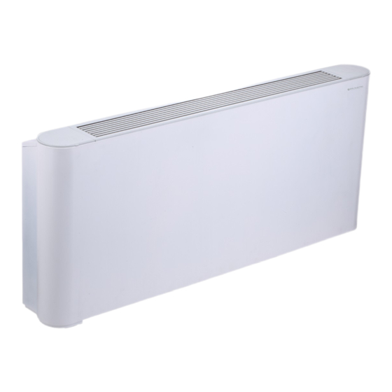
1 VISTA GENERAL DEL PRODUCTO Esta unidad de suelo/techo está diseñada para la regulación de la calidad del aire interior en varios escenarios. El equipo está destinado a ser usado por expertos o capacitados en tiendas, en la industria ligera o granjas o para un uso comercial por personas no cualificadas. -
Page 4: Significado De Diferentes Etiquetas
Para cualquier fallo no recogido por el Manual, contacte al fabricante inmediatamente. La manipulación de la unidad puede provocar situaciones muy peligrosas. El fabricante no es responsable de los daños causados p or la manipulación de la unidad. Las consecuencias por no cumplir con el Manual correrán a cargo del usuario por su cuenta. -
Page 5: Información
Asegúrese de que la tubería de descarga de agua Casos normales En el modo de refrigeración, puede aparecer niebla en pueda proporcionar un drenaje suave. La instalación la salida de aire. incorrecta de la tubería de descarga de agua puede 3.1 Condiciones estándar de uso provocar fugas de agua y daños a los muebles. - Page 6 Refrigeración Calefacción Deshumidificador Auto Área de recepción de la señal remota Pantalla del control por cable Temperatura Velocidad del ventiladopr Velocidad automática del ventilador Botón velocidad del ventilador Botón de modo Botones de ajuste de temperatura Indicador de funcionamiento Botón de retroiluminación Botón On/Off Figure 3-3 Panel del control por cable del fabricante El Manual de funcionamiento se suministra con el control por cable...
-
Page 7: Ajuste De La Dirección Del Flujo De Aire
3.3 Ajuste de la dirección del flujo de aire Se permite limpiar la superficie exterior de la unidad. Puede ajustar manualmente la rejilla para cambiar la Sumerja un paño suave en agua fría y alcohol para dirección del flujo de aire. limpiar la unidad. - Page 8 Intercambiador Rejilla de salida del aire Bandeja de drenaje de calor Junta de salida de agua Caja de control eléctrico Junta de entrada de agua Conexión tubería de drenaje Carcasa Motor Filtro Ventilador Base Figure 4-2 Diagrama de la unidad (expuesta) Intercambiador Rejilla de salida del aire Bandeja de drenaje...
- Page 9 4) Si es necesario, debe: a) Retirar cualquier materia extraña que pueda impedir el flujo de aire. b) Eliminar el polvo con aire comprimido o agua limpia y evitar dañar el intercambiador de calor. c) Secar con aire comprimido. d) Comprobar que no haya impurezas en la tubería de drenaje que puedan impedir el flujo de agua. e) Comprobar si el sistema tiene aire.
-
Page 10: Instrucciones De Instalación
8) Si la unidad o alguno de sus componentes necesita ser retirado, asegúrese de que: Sólo una persona profesional puede desmontar la unidad. El sistema con anticongelante no debe desecharse. De lo contrario, generará contaminación. Debe ser recolectado y luego desechado adecuadamente. - Page 11 Los pies que se muestran en la Figura 5-3 son opcionales. Puedes comprarlos por separado e instalarlos de la siguiente manera: 1. Coloque los pies al lado de la unidad a instalar. 2. Coloque los orificios de montaje en la base de la unidad en el pasador correspondiente de los pies e Montaje de la instale los tornillos ①*2 y ②*2 para fijar los pies de...
- Page 12 Pies Figura 5-8 Figura 5-5 Diagrama de la unidad expuesta en techo Figura 5-9 Posición techo expuesta Figura 5-6 Diagrama de la unidad integrada en techo 5.3.1 Espacio posición La colocación o instalación incorrecta puede aumentar los ruidos y la vibración de la unidad durante su funcionamiento.
-
Page 13: Conexiones De Las Tuberías De Líquido
El uso de agua o aerosoles cerca de la unidad puede provocar una descarga eléctrica y un funcionamiento incorrecto. 5.3.2 Dimensiones Unidad: mm 45 F Figura 5-12 Tabla 5-1 Unidades: mm MODELO EFSL-DC15ST2(T4) EFSL-DC25ST2(R4) EFSL-DC35ST2(T4) EFSL-DC50ST2(T4) EFSL-DC70ST2(T4) EFSL-DC80ST2(T4) 1020 1240... - Page 14 Todas las bobinas del sistema de agua están equipadas con válvulas de descarga y drenaje. Use un destornillador o una llave para abrir y cerrar la válvula. 2) Cuando la instalación esté completa, a) Elimine el aire del interior de las tuberías. b) Envuelva las tuberías de conexión y todo el cuerpo de la válvula con material anticondensación (EPDM o PE) de no menos de 10 mm de grosor o instale un...
-
Page 15: Conexiones Eléctricas
Intercambiador de calor Conector del Bandeja de drenaje sensor de temp. Figura 5-18 Orificios con forma de diamante bloqueados con esponja Caja de control eléctrico Figura 5-19 Retirada de la caja de control eléctrico y bvloqueo de los orificios con forma de diamante 5) Anticongelación El agua en la unidad puede congelarse cuando la unidad no se usa en invierno. - Page 16 AGUA XP6 XS6 Control por cable Ventilador DC XP5 XS5 CN24 CN20 XP4 XS4 XP3 XS3 Swing Motor1 XP2 XS2 Placa principal Swing CN21 Motor2 XP1 XS1 ON/OFF LED Rojo LED Verde Control 0-10V 0..10V por cable GND1 MODBUS RTU A UNIDAD SUPERIOR A CCM.COMM.BUS ENC1...
- Page 17 Seleccione un disyuntor que tenga una separación de contacto en todos los polos de no menos de 3 mm, lo que proporciona una desconexión total, donde se utiliza MFA para seleccionar los disyuntores de corriente y los disyuntores de operación de corriente residual: Tabla 5-2 Modelo EFSL-DC15ST2---EFSL-DC80ST4 Fase 1-fase Fuente Voltaje y frecuencia al i m entaci ó...
-
Page 18: Guía De Puesta En Marcha
5.6 Guía de puesta en marcha La puesta en marcha de la máquina o la primera puesta en marcha debe ser realizada por un profesional. Antes de la puesta en marcha, asegúrese de que la instalación y las conexiones eléctricas se realicen de acuerdo con este Manual y que no haya personal no autorizado cerca de la máquina durante su funcionamiento. -
Page 19: Fallos No Relacionados Con La Unidad
1) Vista general de los códigos de error Si se utiliza un controlador centralizado, aparecen códigos de error en la interfaz de usuario. Póngase en contacto con el personal de instalación e infórmeles sobre el código de error, el modelo de la unidad y el número de serie (puede encontrar la información en la placa de identificación de esta unidad). - Page 20 1.57 Entrada de energía eléctrica total Pelec Nivel de potencia sonora (por ajuste de velocidad, si corresponde) EAS ELECTRIC. Polígono Industrial San Carlos, parcela 13 - 03370 Detalles de contacto Redován (Alicante) MODELO:EFSL-DC15ST4 Información para identificar el (los) modelo (s) con los que se relaciona la información: Elemento Símbolo...
- Page 21 2.60 Entrada de energía eléctrica total Pelec Nivel de potencia sonora (por ajuste de velocidad, si corresponde) EAS ELECTRIC. Polígono Industrial San Carlos, parcela 13 - 03370 Detalles de contacto Redován (Alicante) MODELO:EFSL-DC25ST4 Información para identificar el (los) modelo (s) con los que se relaciona la información: Elemento Símbolo...
- Page 22 5.25 Entrada de energía eléctrica total Pelec Nivel de potencia sonora (por ajuste de velocidad, si corresponde) EAS ELECTRIC. Polígono Industrial San Carlos, parcela 13 - 03370 Detalles de contacto Redován (Alicante) MODELO:EFSL-DC70ST2 Información para identificar el (los) modelo (s) con los que se relaciona la información: Elemento Símbolo...
- Page 23 NOTAS...
- Page 24 Requisitos de calidad del agua en el circuito La calidad del agua debe cumplir los estándares de la Directiva Europea 98/83 CE y los criterios indicados en la Norma UNE 112.076 Antes de conectar la unidad exterior: En las instalaciones tanto nuevas como ya existentes, se debe de realizar una limpieza a fondo de las tuberías utilizando un producto de limpieza químico adecuado, posteriormente se lavarán las tuberías para limpiar el agente químico.
- Page 25 OPERATION AND INSTALLATION MANUAL Fan Coil Unit EFSL-DC15ST2 EFSL-DC35ST2 EFSL-DC70ST2 EFSL-DC15ST4 EFSL-DC35ST4 EFSL-DC70ST4 EFSL-DC25ST2 EFSL-DC50ST2 EFSL-DC80ST2 EFSL-DC25ST4 EFSL-DC50ST4 EFSL-DC80ST4 IMPORTANT NOTE: Original instructions Thank you very much for purchasing our air conditioner, Before using your air conditioner, please read this manual carefully and keep it for future reference.
- Page 26 CONTENTS PRODUCT OVERVIEW WARNING Meaning of Various Labels Warning Note Information OPERATION INSTRUCTIONS Standard Conditions for Use Switch and Control Air Supply Direction Adjustment CLEANING AND MAINTENANCE Maintenance by Customer Professional Maintenance INSTALLATION INSTRUCTIONS Packaging and Assembly Handling Instructions Installation Liquid Pipe Connections Electrical Connection Startup Guide...
-
Page 27: Product Overview
1 PRODUCT OVERVIEW This ceiling and floor type unit is used for indoor air quality regulation in various scenes.This appliance is intended to be used by expert or trained users in shops, in light industry and on farms, or for commercial use by lay persons. NOTE All the illustrations of this manual are for explanatory purpose only. -
Page 28: Meaning Of Various Labels
For any faults not covered by the Manual, please contact the manufacturer immediately. Tampering with the unit can result in very hazardous situations. The manufacturer is not liable for any damages caused by tampering with the unit. The consequences for failing to abide by the Manual shall be borne by the user on its own. 2.1 Meaning of Various Labels Do not install the unit where flammable gas may leak. -
Page 29: Information
Make sure that the water discharge pipeline can In normal cases provide smooth drainage. Improper installation of the In cooling mode, fog may appear at the air outlet. water discharge pipeline may lead to water leakage, 3.1 Standard Conditions for Use and damages to furniture. - Page 30 Cooling Heating Auto Remote Signal Receiving Area Display Area Of the Wired Controller Temperature Fan Speed Automatic Fan Speed Fan Speed Button Mode Button Temp. Setting Button Running Indicator Backlight Button On/Off Button Figure 3-3 Control panel of manufacturer’s wired controller The Operation Manual is provided with the wired controller.
-
Page 31: Air Supply Direction Adjustment
3.3 Air Supply Direction Adjustment Cleaning the outer surface of the unit is permitted. Dip a You can manually adjust the louver to change the air piece of soft cloth in cold water and alcohol to clean the supply direction. unit. - Page 32 Heat exchanger Air outlet grille Drain pan Water outlet joint Electric control Water inlet joint Drain pipe connection Casing Motor Filter Base Figure 4-2 Diagram of unit (exposed) Heat exchanger Air outlet grille Drain pan Water outlet joint Electric control Water inlet joint...
- Page 33 4) If necessary, you should: a) Remove any foreign matters that may impede air flow. b) Remove the dust with compressed air or clean water and avoid damage to the heat exchanger. c) Dry with compressed air. d) Check for any impurities in the drain pipe that may impede water flow. e) Check whether the system has air.
-
Page 34: Installation Instructions
8) If the unit or its parts need(s) to be removed, make sure that: Only a professional person can disassemble the unit. The system with antifreeze must not be discarded; otherwise, it will cause pollution. It should be collected and then be disposed off properly. - Page 35 The footings shown in Figure 5-3 are optional. You can purchase them separately and install them as follows: 1. Put the footings beside the unit to be installed. 2. Place the mounting holes on the unit base into the Casing corresponding footing locating pin and install screws assembly ①*2 and ②*2 to fix the footing according to Figure 5-3.
- Page 36 Footing Figure 5-8 Figure 5-5 Diagram of ceiling exposed Figure 5-9 Ceiling exposed Figure 5-6 Diagram of ceiling concealed 5.3.1 Spacing and Positioning Incorrect positioning or installation may increase the noises and vibration of the unit during operation. If not enough space is reserved during installation, the unit may face difficult maintenance and reduced performance.
-
Page 37: Liquid Pipe Connections
Do not consider the unit as a surface that can be relied on during actual use. Reserve enough space during installation for ventilation purpose. Using water or spray near the unit can cause electric shock and malfunction. 5.3.2 Dimensions Unit: mm 45 F Figure 5-12 Table 5-1 Unit: mm EFSL-DC15ST2(T4) EFSL-DC25ST2(R4) EFSL-DC35ST2(T4) EFSL-DC50ST2(T4) EFSL-DC70ST2(T4) EFSL-DC80ST2(T4) MODEL 1020... - Page 38 All water system coils are equipped with discharge and drain valves. Use a screwdriver or wrench to open and close the valve. 2) When installation is complete, a) Remove air inside pipes. b) Wrap the connecting pipes and all the valve body with anti-condensation material (EPDM or PE) of no less than 10 mm thick or install auxiliary drainage equipment.
-
Page 39: Electrical Connection
Heat exchanger Temperature Drain pan sensor plug Figure 5-18 Diamond-shaped holes blocked with sponge Electric control Figure 5-19 Removing the electric control box and blocking the diamond-shaped holes 5) Anti-freezing The water in the unit may freeze when the unit is left unused in winter. Drain the water system when appropriate if it is not used over a long period. - Page 40 WATER XP6 XS6 Wire controller DC FAN XP5 XS5 CN24 CN20 XP4 XS4 XP3 XS3 Swing Motor1 XP2 XS2 Swing CN21 MAIN BOARD Motor2 XP1 XS1 ON/OFF Red LED Green LED 0-10V Wire 0..10V GND1 controller MODBUS RTU TO UPPER UNIT TO CCM.COMM.BUS ENC1 TO Electric Heating...
- Page 41 Select circuit breaker that having a contact separation in all poles not less than 3 mm providing full disconnection,where MFA is used to select the current circuit breakers and residual current operation breakers: Table 5-2 Model EFSL-DC15ST2---EFSL-DC80ST4 Phase 1-phase Power...
-
Page 42: Startup Guide
5.6 Startup Guide Machine commissioning or first start-up must be performed by a professional. Before startup, make sure that the installation and electrical connections are made in accordance with this Manual, and that no unauthorized personnel is near the machine during operation. 1) Before starting the unit, make sure that: The device is positioned correctly. -
Page 43: Non-Unit Related Faults
1) Error code overview If a centralized controller is used, error codes appear on the user interface. Contact the installation personnel and inform them of the error code, unit model and serial number (you can find the information on the nameplate of this unit). Error Name Running Indicator... - Page 44 Heating capacity Prated,h 1.57 Total electric power input Pelec Sound power level(per speed setting, if applicable) EAS ELECTRIC. Polígono Industrial San Carlos, parcela 13 - 03370 contact details Redován (Alicante) MODEL:EFSL-DC15ST4 Information to identify the model(s)to which the information relation: Item...
- Page 45 Heating capacity Prated,h 2.60 Total electric power input Pelec Sound power level(per speed setting, if applicable) EAS ELECTRIC. Polígono Industrial San Carlos, parcela 13 - 03370 contact details Redován (Alicante) MODEL:EFSL-DC25ST4 Information to identify the model(s)to which the information relation: Item...
- Page 46 Heating capacity Prated,h 5.25 Total electric power input Pelec Sound power level(per speed setting, if applicable) EAS ELECTRIC. Polígono Industrial San Carlos, parcela 13 - 03370 contact details Redován (Alicante) MODEL:EFSL-DC70ST2 Information to identify the model(s)to which the information relation: Item...
- Page 47 NOTE...
- Page 48 Water quality requirements in the circuit The quality of the water must comply with the standards of the European Directive 98/83 CE and the criteria indicated in the Standard UNE 112.076 Before connecting the outdoor unit: In both new and existing facilities, a thorough cleaning of the pipes must be carried out using an appropriate chemical cleaning product, then the pipes will be washed to clean the chemical agent.
Need help?
Do you have a question about the EFSL-DC15ST2 and is the answer not in the manual?
Questions and answers