
Related Manuals for xFusion Digital Technologies DH141C V5


Summary of Contents for xFusion Digital Technologies DH141C V5
- Page 1 DH141C V5 Server Node Technical White Paper Issue Date 2022-04-20 xFusion Digital Technologies Co., Ltd.
- Page 2 Notice In this document, "xFusion" is used to refer to "xFusion Digital Technologies Co., Ltd." for concise description and easy understanding, which does not mean that "xFusion" may have any other meaning. Any "xFusion" mentioned or described hereof may not be understood as any meaning other than "xFusion Digital Technologies Co., Ltd.", and xFusion Digital Technology Co., Ltd.
-
Page 3: Table Of Contents
DH141C V5 Server Node Technical White Paper Contents Contents About This Document ........................ v 1 Product Overview........................7 2 Product Features ........................8 3 Physical Structure........................11 4 Logical Structure ........................13 5 Hardware Description ......................15 5.1 Front Panel ................................15 5.1.1 Front View.................................15... - Page 4 DH141C V5 Server Node Technical White Paper Contents 5.7.2 PCIe Slots .................................29 5.7.3 PCIe Slot Description ............................30 5.8 PSUs ..................................31 5.9 Fan Modules.................................31 5.10 Board .................................32 5.10.1 Mainboard ...............................32 5.10.2 Drive Backplane ..............................34 6 Specifications .......................... 35 6.1 Technical Specifications ............................35 6.2 Environmental Specifications..........................37...
-
Page 5: About This Document
DH141C V5 Server Node Technical White Paper 1 Product Overview About This Document Purpose This document describes the DH141C V5 servers in terms of appearance, performance parameters, and component compatibility. Intended Audience This document is intended for presales engineers. Symbol Conventions... -
Page 6: Change History
DH141C V5 Server Node Technical White Paper 1 Product Overview Change History Issue Release Date Change Description 2022-04-20 This issue is the first official release. 2022-04-20... -
Page 7: Product Overview
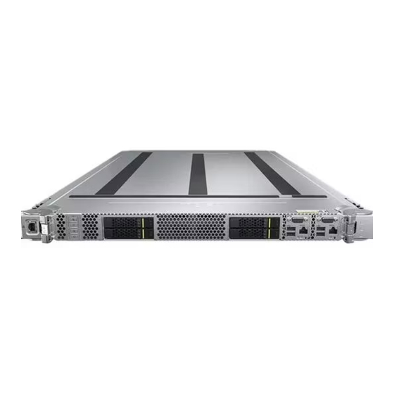
The DH141C V5 delivers supreme performance and high storage density in limited space through innovative design. It is easy to manage and maintain. DH141C V5 contains two nodes. One node supports one main board, and each node supports two 2.5" SAS/SATA drives, sixteen DIMMs, one standard PCIe card and one PCIe screw-in card, and two 10GE onboard NICs. -
Page 8: Product Features
The 1.2 V DDR4 memory saves up to 20% energy than the last-generation 1.35 V DDR3L memory. ⚫ DH141C V5 contains two nodes. Each mainboard supports a maximum of sixteen 2933 MT/s DDR4 ECC DIMMs. The DDR4 ECC DIMMs support registered dual in-line memory modules (RDIMMs) and Load-Reduced DIMMs (LRDIMMs), featuring high speed, increased availability, and a maximum memory capacity of 1 TB. -
Page 9: Energy Efficiency
It supports RAID 0 and RAID 1. ⚫ DH141C V5 nodes provide power bus ports, backplane bus ports and liquid cooling bus ports. The out-of-band management network cables are routed to out-of-band management switches along cabinet enclosures through network ports on the panel. - Page 10 DH141C V5 Server Node Technical White Paper 2 Product Features ⚫ The cellular ventilation holes on the node panel provide higher ventilation density than round holes, increasing the system cooling efficiency. Liquid-Cooled Node Reliability ⚫ The liquid cooling connectors connecting liquid-cooled server to cabinet knock-out unit must adopt quick connectors, namely plug and play, pull and break, leak-proof and automatically closed.
-
Page 11: Physical Structure
DH141C V5 Server Node Technical White Paper 3 Physical Structure Physical Structure Figure 3-1 DH141C V5 physical structure Riser module PCIe card RAID controller card PSU module Power adapter board Chassis Drive Drive backplane Fan module Fan management board 2022-04-20... - Page 12 DH141C V5 Server Node Technical White Paper 3 Physical Structure Mainboard Leakage detection cable Processor DIMM Liquid cooling module 2022-04-20...
-
Page 13: Logical Structure
Technical White Paper 4 Logical Structure Logical Structure Figure 4-1 DH141C V5 logical structure ® ® ⚫ DH141C V5 contains two nodes. Each mainboard supports two Intel Xeon Scalable processors. ⚫ DH141C V5 contains two nodes. Each mainboard supports 16 DIMMs. 2022-04-20... - Page 14 DH141C V5 Server Node Technical White Paper 4 Logical Structure ⚫ The processors interconnect with each other through two UltraPath Interconnect (UPI) links at a speed of up to 10.4 GT/s. ⚫ Processors connect the standard PCIe cards with PCIe bus to provide service ports.
-
Page 15: Hardware Description
DH141C V5 Server Node Technical White Paper 5 Hardware Description Hardware Description 5.1 Front Panel 5.2 Rear Panel 5.3 Processor 5.4 DIMM (DDR4) 5.5 Storage 5.6 Network 5.7 I/O Expansion 5.8 PSUs 5.9 Fan Modules 5.10 Board 5.1 Front Panel 5.1.1 Front View... -
Page 16: Indicators And Buttons
DH141C V5 Server Node Technical White Paper 5 Hardware Description 5.1.2 Indicators and Buttons Indicator and Button Positions Figure 5-2 Front panel indicators and buttons Connection status indicator of UID button/indicator the aggregated network port (mainboard 1) Power button/indicator UID button/indicator... - Page 17 DH141C V5 Server Node Technical White Paper 5 Hardware Description Indicators Silkscreen Description and Buttons off the server node. ⚫ When the power indicator is steady yellow, you can press this button to power on the server node. ⚫ Health status Off: The device is powered off or is faulty.
-
Page 18: Ports On The Front Panel
DH141C V5 Server Node Technical White Paper 5 Hardware Description 5.1.3 Ports on the Front Panel Port Position Figure 5-3 Ports on the front panel VGA port 1 (mainboard 1) VGA port 2 (mainboard 2) Serial port (mainboard 2) USB port (mainboard 2) -
Page 19: Installation Position
DH141C V5 is installed in FusionPoD 700 rack-scale server full liquid cooling cabinet. Each cabinet houses up to 36 DH141C V5 server nodes, with U positions indicated in the figure. The number of configured server nodes depends on the actual power consumption. -
Page 20: Rear Panel
PSU port Used to connect Busbar in the cabinet. 5.3 Processor ⚫ DH141C V5 contains two nodes, and one node supports one mainboard.Each mainboard supports two processors. ⚫ The processor supports heat dissipation by liquid cooling plate. ⚫ Processors used in one server must be of the same model. -
Page 21: Dimm (Ddr4)
DH141C V5 Server Node Technical White Paper 5 Hardware Description ⚫ For details about component options, consult the local sales representatives. Figure 5-7 Processor positions 5.4 DIMM (DDR4) 5.4.1 Memory ID You can determine the memory module properties based on the label attached to the memory module and the following figures and tables. -
Page 22: Memory Subsystem Architecture
⚫ L: LRDIMM 5.4.2 Memory Subsystem Architecture DH141C V5 contains two mainboards. The channels of each mainboard are shown as Table 5-4. Each mainboard supports two processors, each providing 16 memory slots. Each CPU integrates six memory channels. Install the memory modules in the primary memory channels first. If the primary memory channel is not populated, the memory modules in secondary memory channels cannot be used. -
Page 23: Memory Compatibility Information
DH141C V5 Server Node Technical White Paper 5 Hardware Description Memory Channel Memory Slot DIMM050(F) CPU2 2A (Primary) DIMM100(A) DIMM101(G) DIMM110(B) DIMM120(C) 2D (Primary) DIMM130(D) DIMM131(H) DIMM140(E) DIMM150(F) 5.4.3 Memory Compatibility Information Observe the following rules when configuring DDR4 memory modules: ⚫... -
Page 24: Memory Installation Rules
DH141C V5 Server Node Technical White Paper 5 Hardware Description The total memory capacity cannot exceed the maximum memory capacity supported by the CPUs. ⚫ Maximum number of memory depends on the type of CPU, type of memory, number of ranks and operating voltage. -
Page 25: Memory Installation Positions
Comply with the general installation guidelines. 5.4.5 Memory Installation Positions Each mainboard provides 16 memory slots, and DH141C V5 can house up to 32 DDR4 memory modules in total. To maximize performance, it is recommended to use balanced memory configuration. -
Page 26: Memory Protection Technologies
DH141C V5 Server Node Technical White Paper 5 Hardware Description Figure 5-10 DDR4 memory module installation guidelines (2 processors) 5.4.6 Memory Protection Technologies The following memory protection technologies are supported: ⚫ ⚫ Full Mirror ⚫ Address Range Mirror ⚫ SDDC ⚫... -
Page 27: Storage
DH141C V5 Server Node Technical White Paper 5 Hardware Description Figure 5-11 Memory appearance 5.5 Storage 5.5.1 Drive Configurations Table 5-6 Drive configurations Maximum Number of Drive Management Configuration Front Drives Mode Front drives RAID controller card SAS/SATA drives are supported. -
Page 28: Drive Slot Number
DH141C V5 Server Node Technical White Paper 5 Hardware Description 5.5.2 Drive Slot Number Figure 5-12 Drive slot number Table 5-7 Drive slot number Physical Number iBMC Screen Display BIOS Screen Display 5.5.3 Drive Indicators SAS/SATA Drive Indicators Figure 5-13 SAS/SATA drive indicators... -
Page 29: Network
Steady on Steady on The hard drive in the RAID array is faulty. 5.6 Network 5.6.1 LOMs The Lans on Motherboard (LOMs) support network expansion capabilities. Table 5-9 LOMs supported by DH141C V5 Chip Network Netwo Rate Supported Rate Not... -
Page 30: Pcie Slot Description
DH141C V5 Server Node Technical White Paper 5 Hardware Description Figure 5-14 PCIe riser module 5.7.3 PCIe Slot Description DH141C V5 contains two nodes. Each mainboard supports one RAID controller card and one standard PCIe card. Table 5-10 PCIe slot description PCIe PCIe... -
Page 31: Psus
1600 W rated power, with a 48 V to 12 V voltage transformer to meet the power supply requirement of dual nodes. Figure 5-15 Positions of the PSUs 5.9 Fan Modules ⚫ DH141C V5 supports six fan modules. ⚫ Supports single faulty fan. 2022-04-20... -
Page 32: Board
⚫ The fan speed can be adjusted. ⚫ Fan modules configured in a server node must have the same part number. Figure 5-16 Positions of fan modules 5.10 Board 5.10.1 Mainboard DH141C V5 contains two completely the same mainboards. 2022-04-20... - Page 33 DH141C V5 Server Node Technical White Paper 5 Hardware Description Figure 5-17 Mainboard South bridge RAID controller card connector CPU1 DIMM050 connector DIMM040 connector DIMM030 connector DIMM031 connector CPU2 DIMM150 connector DIMM140 connector DIMM130 connector DIMM131 connector Left guide sleeve...
-
Page 34: Drive Backplane
DH141C V5 Server Node Technical White Paper 5 Hardware Description 5.10.2 Drive Backplane Front-drive backplane Figure 5-18 2 × SAS/SATA drive backplane Drive backplane signal Mini-SAS HD connector connector (HDD BP/J21) (PORT A/J3) Power connector (HDD PWR/J2) 2022-04-20... -
Page 35: Specifications
Specifications Form factor 1 U dual-node liquid-cooled server ® Chip set Intel C622 Processors DH141C V5 contains two nodes, and one node supports one mainboard.Each mainboard supports two processors. ® ® ⚫ Intel Xeon Scalable Skylake and Cascade Lake processors are supported. - Page 36 ⚫ Liquid cooling heat dissipation is supported. Storage DH141C V5 contains two nodes, and one node supports one mainboard. Each mainboard supports 2 x SAS/SATA drives. ⚫ For details, see 5.5.1 Drive Configurations .
-
Page 37: Environmental Specifications
DH141C V5 Server Node Technical White Paper 6 Specifications Component Specifications Security feature ⚫ Power-on password. ⚫ Administrator password. ⚫ Secure boot. 6.2 Environmental Specifications Table 6-2 Environmental specifications Item Specifications Temperature ⚫ Operating temperature: 5° C to 45° C (41° F to 113°... -
Page 38: Physical Specifications
DH141C V5 Server Node Technical White Paper 6 Specifications Item Specifications ⚫ When the configuration complies with ASHRAE Class A4 standards and the altitude is above 900 m (2,952.76 ft.), the operating temperature decreases by 1° C (1.8° F) for every increase of 125 m (410.10 ft). -
Page 39: Software And Hardware Compatibility
DH141C V5 Server Node Technical White Paper 7 Software and Hardware Compatibility Software and Hardware Compatibility For details about the OS and hardware, contact the local sales representatives. If incompatible components are used, the device may be abnormal. Such a fault is beyond the scope of technical support and warranty. -
Page 40: Safety Instructions
DH141C V5 Server Node Technical White Paper 8 Safety Instructions Safety Instructions 8.1 Security 8.2 Maintenance and Warranty 8.1 Security General Statement ⚫ Comply with local laws and regulations when installing equipment. These safety instructions are only a supplement. ⚫... - Page 41 DH141C V5 Server Node Technical White Paper 8 Safety Instructions Figure 8-1 Protective clothing ⚫ Before touching a device, wear ESD clothing and gloves (or wrist strap), and remove any conductive objects (such as watches and jewelry). Figure 8-2 shows conductive objects that must be removed before you touch a device.
-
Page 42: Equipment Safety
DH141C V5 Server Node Technical White Paper 8 Safety Instructions Figure 8-3 Wearing an ESD wrist strap ⚫ Exercise caution when using tools that could cause personal injury. ⚫ If the installation position of a device is higher than the shoulders of the installation personnel, use a vehicle such as a lift to facilitate installation. -
Page 43: Maintenance And Warranty
DH141C V5 Server Node Technical White Paper 8 Safety Instructions transported is always kept upright. Take necessary precautions to prevent collisions, corrosion, damp, pollution, or package damage. ⚫ Transport each device in its original packaging. ⚫ If the original packaging is unavailable, package heavy, bulky parts (such as chassis and blades) and fragile parts (such as PCIe cards and optical modules) separately. -
Page 44: System Management
DH141C V5 Server Node Technical White Paper A Appendix System Management The product integrates the latest iBMC intelligent management system (iBMC), which is a remote server management system. It has hardware monitor and management function with high reliability. The main features of iBMC are as follows: ⚫... - Page 45 DH141C V5 Server Node Technical White Paper A Appendix − The iBMC supports keyboard, video, and mouse (KVM) and virtual media to facilitate remote maintenance. − Smart Provisioning implements DVD-free OS installation, RAID configuration, and upgrades, simplifying server installation and configuration.
-
Page 46: A Appendix
DH141C V5 Server Node Technical White Paper A Appendix Appendix A.1 Product SN The serial number (SN) on the right of the server front panel uniquely identifies a device. The SN is required when you contact technical support. Figure A-1 SN example... -
Page 47: Ras Features
DH141C V5 Server Node Technical White Paper A Appendix Description Letters A to C indicate October to December, respectively. − Sequence number (six characters). RoHS compliance (one character). Y indicates environmental-friendly processing. Internal model, that is, product name. A.2 RAS Features The server supports a variety of Reliability, Availability, and Serviceability (RAS) features. - Page 48 DH141C V5 Server Node Technical White Paper A Appendix Module Feature Description Name Data scrambling This feature optimizes data stream distribution and reduces the error possibility to improve the reliability of data streams in the memory and the capability to detect address errors.
- Page 49 DH141C V5 Server Node Technical White Paper A Appendix Module Feature Description Name BIOS abstraction layer for The basic input/output system (BIOS) error handling processes errors and reports the error information to the OS and iBMC in compliance with specifications to improve system serviceability.
-
Page 50: B Term
DH141C V5 Server Node Technical White Paper B Term Term B.1 A-E It collects, processes, and stores sensor signals, and monitors the operating status of components. The BMC provides the hardware status and alarm information about the managed objects to the management system so that the management system can implement unified management of the devices. -
Page 51: Redundant Array Of Independent Disks (Raid)
DH141C V5 Server Node Technical White Paper B Term Hot swap Replacing or adding components without stopping or shutting down the system. B.3 K-O A hardware device that provides public video, keyboard and mouse (KVM). B.4 P-T Panel An external component (including but not limited to ejector levers, indicators, and ports) on the front or rear of the server. -
Page 52: Trusted Platform Module (Tpm)
DH141C V5 Server Node Technical White Paper B Term attachment (SATA) Server A special computer that provides services for clients over a network. System event log System event log. A non-volatile storage area and associated (SEL) interfaces for storing system events for later retrieval. -
Page 53: C Acronyms And Abbreviations
DH141C V5 Server Node Technical White Paper C Acronyms and Abbreviations Acronyms and Abbreviations C.1 A-E Alternating Current Advanced Encryption Standard New Instruction Set Address Resolution Protocol Advanced Vector Extensions Backup Battery Unit BIOS Basic Input/Output System Baseboard Management Controller... - Page 54 DH141C V5 Server Node Technical White Paper C Acronyms and Abbreviations DDR4 Double Data Rate 4 DDDC Double Device Data Correction DEMT Dynamic Energy Management Technology DIMM Dual In-line Memory Module DRAM Dynamic Random-Access Memory Digital Thermal Sensor Digital Video Disc...
- Page 55 DH141C V5 Server Node Technical White Paper C Acronyms and Abbreviations Hard Disk Drive High Performance Computing HTTP Hypertext Transfer Protocol HTTPS Hypertext Transfer Protocol Secure iBMC Intelligent Baseboard Management Controller Industry Canada ICMP Internet Control Message Protocol Internet Data Center...
- Page 56 DH141C V5 Server Node Technical White Paper C Acronyms and Abbreviations Media Access Control Module Management Controller Next Business Day NC-SI Network Controller Sideband Interface Operating System C.4 P-T PCIe Peripheral Component Interconnect Express Power Distribution Unit Physical Layer PMBUS...
- Page 57 DH141C V5 Server Node Technical White Paper C Acronyms and Abbreviations Serial Attached Small Computer System Interface SATA Serial Advanced Technology Attachment Supply Chain Management SDDC Single Device Data Correction SERDES Serializer/Deserializer SGMII Serial Gigabit Media Independent Interface Serial Management Interface...
- Page 58 DH141C V5 Server Node Technical White Paper C Acronyms and Abbreviations C.5 U-Z UEFI Unified Extensible Firmware Interface Unit Identification Light Underwriter Laboratories Inc. Universal Serial Bus VCCI Voluntary Control Council for Interference by Information Technology Equipment Video Graphics Array...
Need help?
Do you have a question about the DH141C V5 and is the answer not in the manual?
Questions and answers