
Related Manuals for SST Automation SSTCOMM GT200-MT-EI


Summary of Contents for SST Automation SSTCOMM GT200-MT-EI
- Page 1 Modbus TCP / EtherNet/IP Gateway GT200-MT-EI User Manual V3.2 SST Automation E-mail: support@sstautomation.com www.SSTAutomation.com...
-
Page 2: Technical Support Contact Information
Important Information Warning The data and examples in this manual cannot be copied without authorization. SST Automation reserves the right to upgrade the product without notifying users. The product has many applications. The users must make sure that all operations and results are in accordance with the safety of relevant fields, and the safety includes laws, rules, codes and standards. -
Page 3: Table Of Contents
GT200-MT-EI Modbus TCP/EtherNet IP Gateway User Manual Table of Contents 1 Product Overview ..............................3 1.1 Product Overview ............................3 1.2 Product Features ............................. 3 1.3 Technical Specifications ..........................3 1.4 Related Products .............................5 1.5 Revision History .............................5 2 Hardware Descriptions .............................. 6 2.1 Product Appearance ............................6 2.2 Indicators ................................ - Page 4 GT200-MT-EI Modbus TCP/EtherNet IP Gateway User Manual 8 Typical Application ..............................48 8.1 EtherNet/IP Master PLCs interconnect with Modbus TCP master PLCs ........... 48 8.2 Modbus TCP Server Devices Connect To EtherNet/IP Network ..............49 www.SSTAutomation.com...
-
Page 5: Product Overview
GT200-MT-EI Modbus TCP/EtherNet IP Gateway User Manual 1 Product Overview 1.1 Product Overview GT200-MT-EI is a gateway which can realize the interconnection of different industrial Ethernet devices. The gateway supports Modbus TCP master/Server and EtheNet/IP adapter. It can finish the data exchange between Modbus TCP network and EtherNet/IP network. - Page 6 GT200-MT-EI Modbus TCP/EtherNet IP Gateway User Manual ◆ Modbus TCP uses EtherNet 1, EtherNet/IP can use EtherNet 1 or EtherNet 2, and defaut use EtherNet 1. ◆ The two Ethernet interfaces cannot use the same network segment. ◆ Cascading is not supported. [2] IP address conflict detection.
-
Page 7: Related Products
GT200-MT-EI Modbus TCP/EtherNet IP Gateway User Manual [11]Installation: 1.4 in (35 mm) DIN RAIL. [12]Protection level: IP20. 1.4 Related Products The related products include: GT200-MT-2RS etc. To get more information about related products, please visit SSTCOMM website: www.sstautomation.com 1.5 Revision History Revision Date Chapter... -
Page 8: Hardware Descriptions
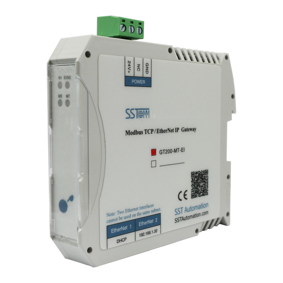
GT200-MT-EI Modbus TCP/EtherNet IP Gateway User Manual 2 Hardware Descriptions 2.1 Product Appearance Dual Power Interface The gateway status indicator EtherNet/IP and Ethernet status indicator Modbus TCP Status Indicator Button Ethernet RJ45 Interface Notes: This picture is for reference only. The product appearance is subject to the actual product. www.SSTAutomation.com... -
Page 9: Indicators
GT200-MT-EI Modbus TCP/EtherNet IP Gateway User Manual 2.2 Indicators Indicators Status Descriptions Blinking(Red) DHCP state (EtherNet 1) (EtherNet 1 network status The IP addresses of EtherNet 1 and EtherNet 2 Red on indicators) are in the same network segment Green on EtherNet/IP connection is established. -
Page 10: Button
GT200-MT-EI Modbus TCP/EtherNet IP Gateway User Manual 2.3 Button Restore Factory Settings: Press and hold the button for 5 seconds within 10 seconds after the device is powered on (the MS light is always on). The MS light will green blinking (2Hz), and click the button within 5 seconds, the MS light will off, the device will be restored to factory settings and automatically restart. -
Page 11: Ethernet Interface
GT200-MT-EI Modbus TCP/EtherNet IP Gateway User Manual 2.4.2 Ethernet Interface Ethernet interface uses RJ-45 connector. Its pin (standard Ethernet signal) is defined as below: Signal Description TXD+, Transmit Data+ TXD-, Transmit Data- RXD+, Receive Data+ Bi-directional Data+ Bi-directional Data- RXD-, Receive Data- Bi-directional Data+ Bi-directional Data- www.SSTAutomation.com... -
Page 12: Hardware Installation
GT200-MT-EI Modbus TCP/EtherNet IP Gateway User Manual 3 Hardware Installation 3.1 Machine Dimension Size (width * height * depth): 0.9in * 3.9in * 4.5in (22.5mm * 99mm * 114.5mm) www.SSTAutomation.com... -
Page 13: Installation Method
GT200-MT-EI Modbus TCP/EtherNet IP Gateway User Manual 3.2 Installation Method Using 1.4 in (35mm) DIN RAIL. www.SSTAutomation.com... -
Page 14: Quick Start Guide
GT200-MT-EI Modbus TCP/EtherNet IP Gateway User Manual 4 Quick Start Guide The following steps will help users to quickly configure GT200-MT-EI: Wiring: Please see Chapter2.4. Please connect the gateway’s network port to the router. Connect to the PC with a network cable for configuring the gateway. -
Page 15: Software Instructions
GT200-MT-EI Modbus TCP/EtherNet IP Gateway User Manual 5 Software Instructions SST-EE-CFG is the software based on Windows platform. It is used to configure GT200-MT-EI series gateway and set the relevant parameters of two different industrial Ethernet. Double-click the icon to enter the main interface of the software: 5.1 Software Interface The main interface of SST-EE-CFG includes: Title bar, Menu bar, Tool bar, equipment plate, configuration plate and comment plate. - Page 16 GT200-MT-EI Modbus TCP/EtherNet IP Gateway User Manual Title Bar Menu Bar Tool Bar Configuration plate: Input configuration parameters, Equipment plate: gray parts cannot be changed. Users can choose operation object, includes Ethernet type and adding node and command. Comment plate: Explain the function of the configuration options.
-
Page 17: Device View
GT200-MT-EI Modbus TCP/EtherNet IP Gateway User Manual Add Node: Add a Modbus TCP Server node. Del Node: Delete a Modbus TCP Server node. Add Command: Add a Modbus command. Delete Command: Delete a Modbus command. Upload Config: Read the configuration information from the module and shown in the software. Download Config: Download the configuration file to the gateway. - Page 18 GT200-MT-EI Modbus TCP/EtherNet IP Gateway User Manual Protocol Mode: EtherNet/IP Adapter. Select EtherNet: EtherNet/IP Adapter network port. Supports EtherNet 1 and EtherNet 2. Default value is EtherNet 1. Assign IP Mode: Manually Assign and DHCP. IP Address: The IP Address of the device. Subnet Mask: The Subnet Mask of the device.
-
Page 19: Modbus Tcp
GT200-MT-EI Modbus TCP/EtherNet IP Gateway User Manual 5.2.2 Modbus TCP 1. Modbus TCP Client Configuration The configurable parameters are as follows: Protocol Mode: Modbus TCP Client, Modbus TCP Server. Select EtherNet: Modbus TCP communication network port. Only supports EtherNet 1. Assign IP Mode: Manually Assign and DHCP. - Page 20 GT200-MT-EI Modbus TCP/EtherNet IP Gateway User Manual Control Word: Supports Disable, All Commands and Only Write Commands. Default value is Disable. Command Output Mode: Serial Output: All commands for a single Modbus TCP Server device are sent one by one, and the next command is sent after receiving a response or timeout. Parallel Output: All commands for a single Modbus TCP Server device are sent together.
- Page 21 GT200-MT-EI Modbus TCP/EtherNet IP Gateway User Manual accounts for the memory mapping address of the gateway through Mapping Address and Bit Offset. Mapping Address(HEX): This function is valid when Device Status is Enable. Address mapped by device status in gateway memory. Range: 0x0000-0x07CF. Bit Offset(0-7):This function is valid when Device Status is Enable.
- Page 22 GT200-MT-EI Modbus TCP/EtherNet IP Gateway User Manual Unit ID(1-255): Modbus TCP Server address. Range: 1-255. Function Code: Modbus Function Code. Starting Address: The starting address for initiating read/write commands in Modbus Server devices. Range: 0-65535. Note: Here is the example of PLC address and corresponding protocol address. Command PLC Address Protocol Address...
-
Page 23: Modbus Tcp Server Configuration
GT200-MT-EI Modbus TCP/EtherNet IP Gateway User Manual Bit Offset (0-7): Modbus function codes 01, 02, 05, 15, can set the position of the bit address in bytes through this parameter. Range: 0-7. Number of Bytes (Read): The number of bytes of data. Displayed in decimal Byte Swap: There are three types: No Swap, Two Bytes Swap, Four Bytes Swap. -
Page 24: Tool
GT200-MT-EI Modbus TCP/EtherNet IP Gateway User Manual Disable: 01 function code corresponds to 0x area coil status data, and 02 function code corresponds to 1x area input status data. Enable: 01 function code corresponds to 1x area input status data, and 02 function code corresponds to 0x area coil status data. - Page 25 GT200-MT-EI Modbus TCP/EtherNet IP Gateway User Manual Method 2: IP Search Click "IP Search" button of the main interface will pop up a dialog box, and user need to enter the IP address of the equipment. Enter the correct IP address, the software will search the network for a GT200-MT-EI device with this IP address. www.SSTAutomation.com...
-
Page 26: Locate
GT200-MT-EI Modbus TCP/EtherNet IP Gateway User Manual After finding the device, click OK, and list the information of the equipment in the main interface. Note: If the users select the "IP search", users need to enter correct IP address or it will not get any devices 5.3.2 Locate When users manage multiple GT200-MT-EI gateways, the “Locate”... -
Page 27: Upload Config And Download Config
GT200-MT-EI Modbus TCP/EtherNet IP Gateway User Manual 5.3.3 Upload Config and Download Config 1. Upload Config Select “Upload” to upload the gateway configuration information from the device to the software. When uploading the configuration from the gateway to the software, the pop-up window is as below: Click “refresh”... - Page 28 GT200-MT-EI Modbus TCP/EtherNet IP Gateway User Manual Select “Download” to download the configured gateway information to the gateway device. The operation of download configuration is the same as upload configuration: Select the gateway you want to configure and click “Download” to enter into the download dialog box. The interface is shown below: Notes: Before downloading, please confirm all configurations have been completed and right.
-
Page 29: Conflict Detect
GT200-MT-EI Modbus TCP/EtherNet IP Gateway User Manual 5.3.4 Conflict Detect It is used to check whether there exists confliction in “Conflict Detcet”. If users find confliction, it can be adjusted in time. The interface is shown below: 1. Command List Operation It shows configured command in the command list interface. -
Page 30: Export Xls
GT200-MT-EI Modbus TCP/EtherNet IP Gateway User Manual Input mapping address range: 0x0000-0x07CF. Output mapping address range: 0x4000-0x47CF. Each grid represents one byte address. Green: Read command is shown in input mapping area, it will be in green without conflict. Yellow: Write command: When address mapping area is located in input area, it will be in yellow without conflict. Blue: When address mapping area is located in output area, it will be in blue without conflict. -
Page 31: Monitor I/O Data
GT200-MT-EI Modbus TCP/EtherNet IP Gateway User Manual shown as below: 5.3.6 Monitor I/O Data This function is used to monitor the buffer data, click “Monitor I/O Data” and it will pop up the dialog box of searching equipment: Click “I/O Monitor”, it will pop up the I/O data monitor dialog box below: www.SSTAutomation.com... -
Page 32: Save And Open Configuration
GT200-MT-EI Modbus TCP/EtherNet IP Gateway User Manual Click “Save Content” button can save relevant content to the PC hard disk. This button becomes “Stop saving”. If you want to finish saving, you can press “Stop saving” button. It can pause displaying buffer data by clicking “Pause Show”. -
Page 33: Open Configuration Project
GT200-MT-EI Modbus TCP/EtherNet IP Gateway User Manual 5.4.2 Open Configuration Project Click the "Open" button on the menu bar or toolbar to open the saved.xml file. Toolbar Menu bar www.SSTAutomation.com... -
Page 34: Working Principle
GT200-MT-EI Modbus TCP/EtherNet IP Gateway User Manual 6 Working Principle 6.1 Modbus TCP Master Ethernet supports Modbus TCP function, described as below: Data exchange of Modbus TCP and EtherNet/IP of GT200-MT-EI is set up through “mapping”. There are two data buffer areas, one is EtherNet/IP network input buffer and the other is EtherNet/IP network output buffer. Network input and output buffer is all for EtherNet/IP master. -
Page 35: Modbus Tcp Server
GT200-MT-EI Modbus TCP/EtherNet IP Gateway User Manual 6.2 Modbus TCP Server 1. Data Exchange Data exchange of Modbus TCP and EtherNet/IP of GT200-MT-EI is set up through “mapping”. There are two data buffer areas, one is EtherNet/IP network input buffer and the other is EtherNet/IP network output buffer. Network input and output buffer is all for EtherNet/IP. - Page 36 GT200-MT-EI Modbus TCP/EtherNet IP Gateway User Manual “network status indicators” is selected as “two ends network monitors with each other” or “EtherNet/IP end monitors Modbus TCP network status”. If “close” monitor function, that means in the configuration software, this parameter is “Modbus TCP end monitors EtherNet/IP network status” or “no indicating”. b.
-
Page 37: Ethernet/Ip Connection Parameters Set
GT200-MT-EI Modbus TCP/EtherNet IP Gateway User Manual 7 EtherNet/IP Connection Parameters Set Connection parameters the gateway provides are as below: a. Input bytes number Instance102, range 5-496 bytes, the default value is 496 bytes. b. Output bytes number Instance 101, range 1-492 bytes, the default value is 492 bytes. c. -
Page 38: Read/Write Data By Io Messaging (Recommend)
GT200-MT-EI Modbus TCP/EtherNet IP Gateway User Manual 7.1 Read/Write Data by IO Messaging (Recommend) Right click on EtherNet/IP scanner module, click "New Module", as shown below: In the pop-up dialog box, unfold "+" before "Communications", choose "ETHERNET-MODULE", click "OK", as shown below: www.SSTAutomation.com... - Page 39 GT200-MT-EI Modbus TCP/EtherNet IP Gateway User Manual Configure relevant information in the pop-up window, as shown below: Set Communication Parameters. Please refer to chapter 6. Set the name. IP address of the SST gateway. In the above picture, the module information needs to be configured includes: Name: Name the added EtherNet/IP adapter module.
- Page 40 GT200-MT-EI Modbus TCP/EtherNet IP Gateway User Manual Comm Format: Configure data types. Users can choose data types as DINT, INT, SINT and REAL, etc. After confirmation, this cannot be changed. If you want to change data types, you can create new module. IP Address: Set IP address of the EtherNet/IP adapter module (IP address of GT200-MT-EI, configured by the software SST-EE-CFG).
- Page 41 GT200-MT-EI Modbus TCP/EtherNet IP Gateway User Manual In the above picture, SSTGateway:O.Data [0] -SSTGateway:O.Data [31] is the corresponding output data address of SST Gateway module in scanner. Unfold "SSTGateway: I", as shown below: In the above picture, the first 4 bytes of SSTGateway: I. Data [0] are the status bytes. SSTGateway:I.Data [1] -SSTGateway: I.
-
Page 42: How To Read/Write I/O Data Using Msg
GT200-MT-EI Modbus TCP/EtherNet IP Gateway User Manual 7.2 How to Read/Write I/O Data using MSG The following RSLogix 5000 example will describe how to read/write I/O data using MSG. 1. Read I/O Data Create a new project. It is in the “Offline” mode. Add two new tags “ReadTag” and “ReadData” under the “Controller Tags”... - Page 43 GT200-MT-EI Modbus TCP/EtherNet IP Gateway User Manual In the new pop-up window, it needs to set some parameters as below: Message Type: CIP Generic. Service Type: Select “Get Attribute Single”, now, relevant service code will become “e (Hex)”. Class: 4 (Hex). Instance: 102 .
- Page 44 GT200-MT-EI Modbus TCP/EtherNet IP Gateway User Manual Select “Communication” label, first click “Browse” button. Select the gateway PLC has connected with, click “OK” to confirm: Shown as picture below, add a “MSG” command and select “ReadTag” as “Message Control” in the “MainRoutine”...
-
Page 45: Write I/O Data
GT200-MT-EI Modbus TCP/EtherNet IP Gateway User Manual Download the program to the PLC and set PLC into “Online” state. PLC read-data command Click “Control Tags” and select “Monitor Tags”, unfold “ReadData”, you will see that PLC can read the data of Modbus TCP master or Modbus TCP Server through the gateway GT200-MT-EI. - Page 46 GT200-MT-EI Modbus TCP/EtherNet IP Gateway User Manual Enter the “Monitor Tags” interface, input some data in the “WriteData” tag. There data will be outputted to GT200-MT-EI through PLC. Described as below picture, 0x10, 0x20, 0x30, 0x40, 0x50, 0x60, 0x70, 0x80 and 0x90 are the data that will be outputted.
- Page 47 GT200-MT-EI Modbus TCP/EtherNet IP Gateway User Manual In the new pop-up window, it needs to configure as below: Message Type: CIP Generic. Service Type: Select “Set Attribute Single”, now, relevant Service Code will become “10 (Hex)”. Class: 4 (Hex). Instance: 101 . Attribute: 3 (Hex).
- Page 48 GT200-MT-EI Modbus TCP/EtherNet IP Gateway User Manual Select “Communication” label, first click “Browse” button, select the gateway PLC connected in the new window, click “OK” to confirm: Note: When the number of output bytes in MSG exceeds 500 bytes, check Large Connection. www.SSTAutomation.com...
- Page 49 GT200-MT-EI Modbus TCP/EtherNet IP Gateway User Manual Shown as below, add a “MSG” command in the “MainRoutine” of “MainProgram” and select “WriteTag” as “Message Control”. Download PLC program to the PLC and set PLC to “Online” state, the data in “WriteData” will be outputted to Modbus TCP master or Server through GT200-MT-EI.
-
Page 50: Typical Application
GT200-MT-EI Modbus TCP/EtherNet IP Gateway User Manual 8 Typical Application GT200-MT-EI can connect Modbus TCP Server equipment to the EtherNet/IP network, it can also realize the interconnection between Schneider Modbus TCP master PLC and AB EtherNet master PLC. Here are some typical applications of GT200-MT-EI. 8.1 EtherNet/IP Master PLCs interconnect with Modbus TCP master PLCs In this case, different EtherNet/IP masters are connected to the same Modbus TCP master PLC with many... - Page 51 GT200-MT-EI Modbus TCP/EtherNet IP Gateway User Manual 8.2 Modbus TCP Server Devices Connect To EtherNet/IP Network In this application case, GT200-MT-EI gateway needs to be configured as EtherNet/IP adapter and Modbus TCP master. EtherNet/IP master devices, Modbus TCP Server devices, and industrial Ethernet gateway GT200-MT-EI connect with each other through Ethernet switch machine.
Need help?
Do you have a question about the SSTCOMM GT200-MT-EI and is the answer not in the manual?
Questions and answers