SST Automation SSTCOMM GT200-HT-MT User Manual
Hart / modbus tcp gateway
Hide thumbs
Also See for SSTCOMM GT200-HT-MT:
- User manual (74 pages) ,
- User manual (45 pages) ,
- User manual (89 pages)

Related Manuals for SST Automation SSTCOMM GT200-HT-MT


Summary of Contents for SST Automation SSTCOMM GT200-HT-MT
- Page 1 HART / Modbus TCP Gateway GT200-HT-MT User Manual V 1.2 Rev E SST Automation Email: SUPPORT@SSTAUTOMATION.COM SUPPORT@SSTCOMM.COM WWW.SSTAUTOMATION.COM WWW.SSTCOMM.COM...
- Page 2 The product has many applications. The users must make sure that all operations and results are in accordance with the safety of relevant fields, and the safety includes laws, rules, codes and standards. Copyright Copyright © 2022 by SST Automation. All rights reserved. Trademark is the registered trade mark of SST Automation.
-
Page 3: Table Of Contents
Catalog 1 Product Overview ..............................1 1.1 Product Function ............................1 1.2 Product Features ............................. 1 1.3 Technical Specifications ..........................1 1.4 Related Products .............................2 1.5 Revision History .............................2 2 Hardware Descriptions .............................. 3 2.1 Product Appearance ............................3 2.2 LED Indicators ............................... 4 2.3 Configuration Switch/Button ......................... - Page 4 6.1 Address Table ............................... 40 6.2 Flowchart of Executing One HART Command ...................43 6.3 Trigger Command ............................43 WWW.SSTAUTOMATION.COM...
-
Page 5: Product Overview
1 Product Overview 1.1 Product Function The GT200-HT-MT achieves seamless communication between HART instruments and a Modbus TCP network. The HART interface can be configured as a primary master or a secondary master. It acts as a server at the Modbus TCP side. -
Page 6: Related Products
[7] Ethernet 10/100M adaptive. Supports IP address conflict detection and automatic routing functions. [8] Supports connection with up to 36 Modbus TCP clients and 512 requests simultaneously. [9] The Ethernet interface can be configured as a Modbus TCP server, supporting function codes:03H, 04H, 06H, 10H. -
Page 7: Hardware Descriptions
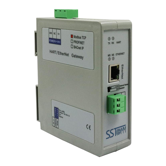
2 Hardware Descriptions 2.1 Product Appearance HART Indicators Power Interface Ethernet Indicators Ethernet interface Resistor Switch HART Interface DIP Switch Notes: This picture is for reference only. The product appearance is subject to the actual product. WWW.SSTAUTOMATION.COM... -
Page 8: Led Indicators
2.2 LED Indicators State Description Flashing HART channel is sending data No data sending Flashing HART channel is receiving data No data is received Communication error in Modbus TCP network Flashing Communication running IP address conflicts Connection is OFF / Configuration Mode / DHCP, Red, flashing BOOTP, IP address conflict detection Red, flashing... -
Page 9: Interface
When the power of the series resistor is more than 2W, you must use an external series resistor (250Ohm/3W), supporting up to 15 HART instruments to be connected. Switch to ON, using the internal series resistor Switch to OFF, using the external series resistor 2.4 Interface 2.4.1 Power Interface Description... -
Page 10: Hart Interface
2.4.3 HART Interface HART LOOP+ HART LOOP- Signal Description HART LOOP+ Connected to HART signal+ HART LOOP- Connected to HART signal- Not connected WWW.SSTAUTOMATION.COM... -
Page 11: Topology Of Gt200-Ht-Mt And Hart Instruments
2.5 Topology of GT200-HT-MT and HART Instruments Notes: It is recommended to use the separate power supply for the HART instruments and the GT200-HT-MT, to ensure stable communication. To improve the communication efficiency of the field bus, it is recommended not to configure the empty node in SST-HE-CFG software or useless commands. - Page 12 WWW.SSTAUTOMATION.COM...
-
Page 13: Hardware Installation
3 Hardware Installation 3.1 Mechanical Dimensions Size: 1.6 in (width) *5.0 in (height) *4.4 in (depth) WWW.SSTAUTOMATION.COM... -
Page 14: Mounting Method
3.2 Mounting Method Using 1.38 in (35mm) DIN RAIL. Install the gateway Uninstall the gateway 1. Use a screwdriver to pass through the DIN RAIL bar, pull down and hold. 2. Pull out the gateway. 3. Lift up the gateway. ③... -
Page 15: Quick Start Guide
4 Quick Start Guide 4.1 Start 4.1.1 Connection 1. Set the setting switch to Bit1 ON and Bit2 OFF. 2. Connect the GT200-HT-MT with PC in Ethernet interface. 3. Power on the GT200-HT-MT. Now the IP address of the gateway is fixed 192.168.0.10 and it is configurable. 4.1.2 Default Configuration 1. -
Page 16: Configuration
are shown below.) Command ID3 is pre-configured to read the PV, SV, TV, and QV. (For your reference, the default configuration of this command are shown below.) 4.1.3 Configuration 1. Open the SST-HE-CFG software installed on your computer. 2. Click "Fieldbus" in the "Mode" item on the right and choose “Modbus TCP”. 3. - Page 17 4. Click "OK". Select the gateway and sign in. 5. Select the "Fieldbus" on the left and configure the parameters as below. 6. Click the HART channel on the left, configure the parameters as below: WWW.SSTAUTOMATION.COM...
- Page 18 7. Right click the channel, select “Add Node”: 8. Right click on “Node(0)” and select "Add Command" and add Command ID1 box (double click on “Command ID1” or select "Command ID1" and click "»"). Click OK. WWW.SSTAUTOMATION.COM...
- Page 19 9. Click “Command ID1” and configure the parameters as below: 10. Click the download icon . Select the port and click Download: WWW.SSTAUTOMATION.COM...
-
Page 20: Communication With Modbus Tcp Client
4.2 Communication with Modbus TCP Client The GT200-HT-MT is able to connect HART instruments to Modbus TCP network. It works as a Modbus TCP server. The following example shows how the GT200-HT-MT communicate with Modbus Poll (a Modbus simulator software). Configure the GT200-HT-MT with some HART nodes and commands. - Page 21 (3) Command 6: 2-byte request and 2-byte response. The response data length includes the command status bytes. After mapping the data, check the buffer address in Conflict Detection window. The request data bytes of command 6 is stored in 3000~3001 bytes. The response data bytes of command 1 are stored in 0~7 bytes, command 3 in 8~19 bytes and command 6 in 20~23 bytes.
- Page 22 This example uses Modbus Poll on the computer to simulate the Modbus TCP client. Set the correct server IP and read/write parameters. You can use the advanced function Memory Data Display (see chapter 5.2.7) or Diagnose (see chapter 5.2.8) to monitor the HART communication. (1) Memory Data Display WWW.SSTAUTOMATION.COM...
- Page 23 (2) Diagnose: According to the specifications of HART command, you can convert the hexadecimal data to float number. WWW.SSTAUTOMATION.COM...
-
Page 24: Software Instructions
5 Software Instructions 5.1 Software Interface Description SST-HE-CFG is the configuring software based on Windows platform, used to configure HART series gateway. Open the SST-HE-CFG and enter the main interface of software: Menu Bar Tool Bar Equipment section: You can choose the field bus or subnet, and add the nodes and Configuration section: commands. - Page 25 DelNode: Delete a HART node (device) AddCmd: Add a HART command DelCmd: Delete a HART command Upload: Upload the configuration from the GT200-HT-MT and open it in the software Download: Download the configuration to the GT200-HT-MT AutoMap: Automatically calculate the mapping address Conflict: To check whether there are some conflicts in the data buffer Export: Output the configuration and save it as an Excel form Memory: Show the data in the buffer of the GT200-HT-MT.
-
Page 26: Software Functional Specifications
5.2 Software Functional Specifications 5.2.1 Configure the Fieldbus Click the "Fieldbus" on the left and select "Modbus TCP" in the "Mode" in the configuring plate on the right, as shown below: Assign IP Mode: Manual Assign, BOOTP, DHCP optional. IP Address: Set the IP address of the GT200-HT-MT. Subnet Mask: Set the subnet mask of the GT200-HT-MT. -
Page 27: Configure The Hart Fieldbus
5.2.2 Configure the HART Fieldbus 5.2.2.1 Set the Parameters of HART Channel Click the "HartChannel0" on the left, then the configuration plate will be shown as below: Master type: Primary master, Secondary master optional. Network mode: Select the network mode of HART. In “point-to-point” mode, only one HART instruments of address 0 can be connected. - Page 28 5.2.2.2 Add Slave Nodes Click the selected HART channel, right click on it and select "Add Node" in the pop-up menu. Click the added node, set device address in the right configuration plate. Notes: When configured node numbers are more than the actual connected devices, the redundant node will lead to the longer time of polling output.
- Page 29 Choose the command you want to add in the pop-up dialog box, and then click "OK" to exit: Notes: The same command can only be configured once in one node. ※HART Common Commands Note: The front two bytes of the actual response data is the status info of the device. The data after that two bytes is the device response data.
- Page 30 As the request is: “None”, the user should fill “0” for the section “Length of Sending Data (BYTE)” The “Length of Receiving Data (BYTE)” will be 7, which is the sum of 2 status bytes and 5 device response bytes. Command 3 (Command ID 3): Read Dynamic Variable and Primary Variable Current Read primary variable current and four (at most) pre-defined dynamic variables.
- Page 31 As the request is: “None”, the user should fill “0” for the section “Length of Sending Data (BYTE)” The “Length of Receiving Data (BYTE)” will be 26, which is the sum of 2 status bytes and 24 device response bytes If the user does not need to map all the variables to the Modbus TCP registers.
- Page 32 5.2.2.4 Configure Slave Commands Click the command ID on the left, you will see the configuration plate of the command on the right: Mode of outputting command: Change-of-state, polling output, Initialization output and disable output optional. Change-of-state output: Execute this command once the data buffer changes WWW.SSTAUTOMATION.COM...
- Page 33 Polling output: The command is put in the polling list and executed periodically Initialization output: Execute the command once, when power is on Disable output: The command will not be sent. Memory starting address of sending data: Set the start address in data buffer of output data of this command and the range is 3000~4999.
- Page 34 main variable of No.1 HART command, and need to filter the unit of the main variable. The input data of the HART command is divided into segments that can be extracted independently. Users can get any part data they want. Click "configuration"...
-
Page 35: Conflict Detection
“Primary Variable” in the left bottom area. Memory Address: Set the start address of these bytes in data buffer. Starting address: This parameter is automatically calculated and is the relevant Modbus register address of "Memory Address". Byte swap: "No swap" and "Register swap" is optional, which is only valid to float type data. For example, the original data is 0x12345678, it will be 0x56781234 when using "register swap". -
Page 36: Auto Mapping
Green color areas are occupied addresses. When one memory address is configured with two commands or more, it will display red. When the mapping address of a command exceeds the defined range of the GT200-HT-MT, the exceeding part will display yellow. Click on a command, the corresponding parts are shown in blue. -
Page 37: Upload Configuration
5.2.5 Upload Configuration Select “Config” >> “ Ethernet Config” in the menu bar: The "Ethernet Configuration" box is shown as below: When ticking "Use the search function", it will search all identifiable hardware and show them in the device list: WWW.SSTAUTOMATION.COM... - Page 38 Select a device and click "Sign in" to connect the device. When not ticking "Use the search function", it will only search the appointed hardware and only show this hardware in the device list. Click the upload icon again, the pop-up box is shown as below: Click "Upload data"...
-
Page 39: Download Configuration
Now, user can upload the configuration of the GT200-HT-MT into the software and open it in the software. 5.2.6 Download Configuration After configuring the command, click button, the pop-up box is as shown below. Click "Download data". Notes: Before downloading, please confirm all configuration is correct. 5.2.7 Memory Data Display This function helps users to check the data in buffer of the GT200-HT-MT, following these steps: Ensure that the Bit 1 and Bit 2 of the status setting switch are OFF, then restart the gateway. -
Page 40: Diagnose
The upper table shows the memory distribution of HART input data, and the lower table shows the output data. When you need to modify the output data, first click the "Stop" button. Then modify the required data or load the already saved data table. At last, click the "Send". 5.2.8 Diagnose This function helps users to check the communication status of HART instruments, the execution of HART commands, the status of data transmission and reception. - Page 41 "Tool" >> "Select Mode" and select debug mode. You can also click to change mode. Click and upload the configuration of the required gateway, as shown below: Click "Upload data": Click "OK" to open the diagnostic box. Click "Channel 1" and the right side will display the status of the HART fieldbus.
- Page 42 Click Node (x) and the response status of the configured commands will be shown on the right. Double click on a command and the detailed information will be show in the pop-up box. For example, double click on "CMD 0": WWW.SSTAUTOMATION.COM...
-
Page 43: Switching Tools
Click "Refresh" to update the data. "Edit" in the read-only command does not work. 5.2.9 Switching Tools There are two practical tools in the "Tools" menu to convert hexadecimal data to 1EEE754 floats or PACKED ASCII codes. WWW.SSTAUTOMATION.COM... -
Page 44: Working Principle
6 Working Principle 6.1 Address Table The GT200-HT-MT has a memory buffer of 8156 bytes. 0 to 4999 of the buffer is used for the HART input data and output data. 5000~8155 of the buffer is used for the status of the HART channel and control bytes. Modbus Address HART Buffer... - Page 45 GT200-HT-MT, with the specified address. The Modbus address in the above table is based 0 and decimal. For example, the Modbus address 0-1499 for the HART input data, is also the 3x0001-3x1500 as PLC address (based 1). For more example, please see chapter 4.2 Communication with Modbus TCP Client. Read/Write (1) Read: The Modbus TCP client can only use function code 04 to read these data from the GT200-HT-MT.
- Page 46 Configured HART command status: The status of configured HART command(s). These commands are configured in SST-HE-CFG software and will generate a unique “Command index”. The status will be arranged in index order. For example, the high byte of 2670 input register (3x2671) is the status of the command of index 00, and the low byte of 3x2671 register is the status of the command of index 01.
- Page 47 6.2 Flowchart of Executing One HART Command 6.3 Trigger Command Users can trigger any HART command by sending a trigger byte and command index, following the steps below: (The address table refers to chapter 6.1) Disable the polling output. You can disable it in SST-HE-CFG software or by changing the “Polling output control byte”...
- Page 48 Now the command of the index in “Triggered command index” address is triggered. The response data bytes will be stored in the corresponding buffer address. WWW.SSTAUTOMATION.COM...
Need help?
Do you have a question about the SSTCOMM GT200-HT-MT and is the answer not in the manual?
Questions and answers