
Related Manuals for SST Automation GT200-MQ-BMT


Summary of Contents for SST Automation GT200-MQ-BMT
- Page 1 Modbus TCP / BACnet IP / MQTT Gateway GT200-MQ-BMT User Manual V 1.3 Rev A SST Automation Email: support@sstautomation.com www.SSTAutomation.com...
- Page 2 Important Information Warning The data and examples in this manual cannot be copied without authorization. SST Automation reserves the right to upgrade the product without notifying users. The product has many applications. The users must make sure that all operations and results are in accordance with the safety of relevant fields, and the safety includes laws, rules, codes and standards.
-
Page 3: Table Of Contents
Catalog 1 Product Overview ..............................1 1.1 Product Function ............................1 1.2 Product Features ............................. 1 1.3 Technical Specifications ..........................1 1.4 Revision History .............................3 2 Hardware Description ..............................4 2.1 Product Appearance ............................4 2.2 LED Indicators ............................... 5 2.3 Configuration Button ............................6 2.4 Interfaces ................................ - Page 4 6.1 Use Case 1: Modbus TCP Client/Servers to MQTT ..................32 6.2 Use Case 2: BACnet IP Client to MQTT .....................33 6.3 Use Case 3: Modbus TCP Client/Servers and BACnet IP Client to MQTT ..........34...
-
Page 5: Product Overview
1 Product Overview 1.1 Product Function The GT200-MQ-BMT is a gateway that enables data exchange among Modbus TCP client/servers, a single BACnet IP client, and MQTT network. It can connect a wide range of PLCs (e.g., Siemens, Schneider, etc.), Modbus fieldbus instruments, and BACnet IP controllers to the cloud servers (e.g., Microsoft Azure, Amazon AWS, and custom servers) over a wired Ethernet connection (WAN) using the MQTT protocol. - Page 6 [3] Modbus TCP features: Supports Modbus TCP client and server. Supports up to 36 Modbus TCP connections. Supports up to 128 Modbus commands. Supports function code: 01, 02, 03, 04, 05, 06, 15, 16. Modbus TCP client supports maximum 2048 input/output bytes. ...
-
Page 7: Revision History
1.4 Revision History Revision Date Chapter Description V1.3 Rev A 6/8/2023 MQTT Chapters Added details on how to configure 5.4.4 and 5.4.5. Microsoft Azure and Amazon AWS. V1.3 5/9/2023 New release www.SSTAutomation.com... -
Page 8: Hardware Description
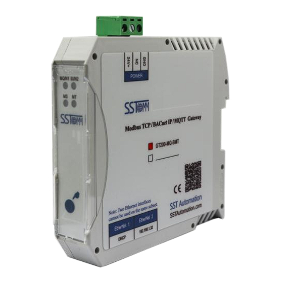
2 Hardware Description 2.1 Product Appearance Power Interface Indicators Configuration Button Dual Ethernet Interface Note: This picture is for reference only. The product appearance is subject to the actual product. www.SSTAutomation.com... -
Page 9: Led Indicators
2.2 LED Indicators Indicators Function MQ/N1 (Top Left) Network status of MQTT and EtherNet 1 BI/N2 (Top Right) Network status of BACnet IP and EtherNet 2 MS (Bottom Left) Module Status MT (Bottom Right) Network status of Modbus TCP Indicators State Description Solid Green... -
Page 10: Configuration Button
2.3 Configuration Button The configuration button is located on the front of the gateway. There are two functions below. 1. Restore Factory Settings Within 10 seconds of completing the device's power-on startup (i.e., when the MS green light is constantly on), press and hold the button for 5 seconds, the MS green light will blink (2Hz). -
Page 11: Interfaces
2.4 Interfaces 2.4.1 Power Interface The GT200-BM-MT gateway uses a 24V DC power supply. 24V+ Description NC (Not Connected) 24V+, DC 2.4.2 Ethernet Interface The two Ethernet interface uses an RJ-45 connector and follows the IEEE802.3u 100BASE-T standard. Its pin (standard Ethernet signal) is defined as below. -
Page 12: Hardware Installation
3 Hardware Installation 3.1 Mechanical Dimensions Size (width * height * depth): 0.9 in * 3.9 in * 4.5 in (22.5 mm * 108 mm * 114.5 mm) www.SSTAutomation.com... -
Page 13: Installation Method
3.2 Installation Method Using 1.4 in (35 mm) DIN RAIL. Install Uninstall www.SSTAutomation.com... -
Page 14: Quick Start Guide
Note: If you cannot find the GT200-MQ-BMT gateway, check your Hardware configuration or your network configuration. Refer to the note How to Use the Ping Command. This is a default configuration created by SST Automation. If you would like to create a configuration from the beginning simply click "New". - Page 15 7. Add or edit MQTT Topic. 8. Click the"Fieldbus to Fieldbus" under the Management and configure the settings to your needs under the Configuration Window. 9. Once configuration is complete, click "Download" to download your configuration into GT200-MQ-BMT gateway. 10. Test the communication.
-
Page 16: Software Instructions
“Help -> Content” in the SST-BMQ-CFG software. Note: The factory default network settings for EtherNet 1 and EtherNet 2 of GT200-MQ-BMT gateway is DHCP and 192.168.1.32 respectively. www.SSTAutomation.com... -
Page 17: Software Main Interface
5.1.1 Software Main Interface The software interface includes: Title bar, Menu bar, Toolbar, Configuration Window and Tree View. Note: The grayed out parameters cannot be changed. Title Bar Menu Bar Tag Configuration Window Toolbar Tree View Configuration Window Comment Field www.SSTAutomation.com... -
Page 18: Toolbar
5.1.2 Toolbar 1. When selecting the “Modbus TCP” option in the Tree View, the Toolbar interface has the following functions as shown in the figure below: The functions from left to right are: New, Save, Open, Add Node, Delete Node, Add Command, Delete Command, Upload, Download, Tag Rename, I/O Monitor, and Export. - Page 19 2. When selecting the "Fieldbus to MQTT" option in the Tree View, the Toolbar interface has the following functions as shown in the figure below: The functions from left to right are: Add Topic, Delete Topic, Add Tag, and Delete Tag. The other options have the same functionality as when selecting “Modbus TCP”.
-
Page 20: Bacnet Ip Configuration
'EtherNet1' and 'EtherNet2'. 'EtherNet1' corresponds to network port 1, and 'EtherNet2' corresponds to network port 2. Device Name: The name used to identify the GT200-MQ-BMT in order to distinguish it from other devices. Note: The name cannot have spaces and can have a maximum length of 16 characters. -
Page 21: Bacnet Ip Protocol Configuration Interface
5.2.2 BACnet IP Protocol Configuration Interface The BACnet IP Protocol configuration interface is shown below: BACnet IP Port: The GT200-MQ-BMT’s BACnet IP port number. Range: 1-65535. Default value is 47808. Device Instance: The GT200-MQ-BMT’s device instance number. Range: 0-4194303. Default value is 100. -
Page 22: Tag Configuration
5.2.3 Tag Configuration Select "BACnet IP" in the left tree view to enter the BACnet IP tag configuration window. The BACnet IP tag configuration window is shown below: Tag Area: Displays the tag object type. The available object types are AI, AO,AV, BI, BO, BV, MSI, MSO, and MSV. -
Page 23: Modbus Tcp Configuration
5.3 Modbus TCP Configuration Double click "Modbus TCP" in the left tree view to open the Modbus TCP configuration window. 5.3.1 Modbus TCP Network Configuration Interface The Modbus TCP Network configuration interface is shown below: The parameters have the same definitions as with the "BACnet IP Network Configuration Interface". Please refer Chapter 5.2.1. -
Page 24: Modbus Tcp Protocol Configuration Interface
5.3.2 Modbus TCP Protocol Configuration Interface The GT200-MQ-BMT supports Modbus TCP connections and can function as either a Client or a Server. The Modbus TCP mode for the device has can be set by changing the "Protocol Mode" in the Protocol Configuration Interface. - Page 25 5.3.2.2 Modbus TCP Server Mode The Modbus TCP Server mode protocol configuration interface is shown below: Protocol Mode: Modbus TCP Client station. As the Modbus TCP Client device, the gateway establishes communication with Modbus TCP server devices. Coil Status Starting Address: The starting address of the 0XXXX area. Range: 0-65535. The default is 0. Coil Status Block Size: The block size of the 0XXXX area.
-
Page 26: Node Configuration
Function Code 03/04 Exchange: Disable: Function code 03 corresponds to the maintained register data in area 4XXXX, and function code 04 corresponds to the input register data in area 3XXXX. Enable: Function code 03 corresponds to the maintained register data in area 3XXXX, and function code 04 corresponds to the input register data in area 4XXXX. -
Page 27: Command Configuration
5.3.3 Command Configuration Right click "Node(X)" in the left tree view to add Modbus Commands. Double click a command in the left tree view to enter the command configuration window. The Modbus command configuration window is shown below: Function Code: Modbus Function Code. Starting Address: The starting address of register or switching value or loop and so on in Modbus TCP slave and the range is 0-65535. -
Page 28: Mqtt Configuration
5.4 MQTT Configuration Double click "Fieldbus to MQTT" in the left tree view to open the MQTT configuration window. 5.4.1 MQTT Network Configuration Interface The MQTT Network configuration interface is shown below: The parameters are have the same definitions as with the "BACnet IP Network Configuration Interface". Please refer to Chapter 5.2.1. -
Page 29: Mqtt Protocol Configuration Interface
MQTT Broker Port: The default value is 1883. The value ranges from 1 to 65535. SSL/TLS: This parameter is disabled by default and supports enabled, disabled and Bidirectional authentication. If you want to connect GT200-MQ-BMT to AWS, Azure IoT or other Cloud provider using certificate, please select Bidirectional. -
Page 30: Mqtt Topic Configuration
this option as the default when there is no special requirement. You can enter characters of English, numbers and special symbols, and the length is less than 90 characters. Object Model Communication: This parameter is disabled by default and supports disabled and enabled. Custom Message Format: This parameter is disabled by default and supports disabled and enabled. -
Page 31: Connecting To Microsoft Azure
important data. QoS 1: There will be an ACK to ensure that the Client or Server receives the data. The data will be sent all the time until it is successfully received. 5.4.4 Connecting to Microsoft Azure The GT100-MQ-RS supports the following device authentication methods to connect to Azure IoT: 1. - Page 32 Client Key File* <Private Key.pem.key> Publish Topic devices/<deviceID>/messages/events/ Subscription Topic devices/<deviceID>/messages/devicebound/# *Note: Certificates and keys must be in PEM format. 3. Signed X.509CA Certificate: When creating a device in Azure IoT, it is necessary to register the X.509 CA certificate to your IoT Hub. Detailed instructions can be found on Microsoft’s website.
-
Page 33: Connecting To Amazon Aws
5.4.5 Connecting to Amazon AWS To connect the GT100-MQ-RS to AWS IoT, configure the MQTT broker address and port, enable TLS and import the correct certificates (CA Certificate, Client Certificate, and Client Key). The following fields in the SST-MQT-CFG configuration software will need to match the following format to connect to AWS: Property Format MQTT Broker Username... -
Page 34: Mqtt Tag Configuration
5.4.6 MQTT Tag Configuration Select a Topic in the left tree view to view the Tag Configuration window. The MQTT Tag configuration window is shown below: Source: Data tag mapped to the other end. Tag Name:Can be modified, support case and case English characters, numbers, can input 1~32 characters. ExeSeq: The default is Default, and there are Default and Scale before Byte Swap options. -
Page 35: Fieldbus To Fieldbus Configuration
NwFault: The default is Hold, and there are Hold and Clear options. Hold: When input end network timed out, the output end keeps the last correct data received. Clear: When input end network timed out, the output data will be cleared. Note: Modbus TCP client mode supports Hold/Clear after network timeout, while Modbus TCP server and BACnet IP only support Hold. -
Page 36: Typical Application
6 Typical Application GT200-MQ-BMT gateway can realize the data exchange among Modbus TCP client/server devices, BACnet IP client, and MQTT. The following is three typical application. Use Case 1: Modbus TCP Client/Servers to MQTT www.SSTAutomation.com... - Page 37 Use Case 2: BACnet IP Client to MQTT www.SSTAutomation.com...
- Page 38 Use Case 3: Modbus TCP Client/Servers and BACnet IP Client to MQTT www.SSTAutomation.com...
Need help?
Do you have a question about the GT200-MQ-BMT and is the answer not in the manual?
Questions and answers