
Related Manuals for SST Automation GT200-MT-CA


Summary of Contents for SST Automation GT200-MT-CA
- Page 1 EtherNet / CAN Gateway GT200-MT-CA User Manual REV 1.0 SST Automation E-mail: SUPPORT@SSTCOMM.COM WWW.SSTCOMM.COM...
-
Page 2: Table Of Contents
GT200-MT-CA EtherNet to CAN Gateway User Manual Catalog 1 About This Document..............................4 1.1 General................................4 1.2 Important Information............................ 4 1.3 Related Products............................. 4 2 Product Overview..............................5 2.1 Product Function.............................5 2.2 Technical Specifications..........................5 2.2.1 Modbus TCP/CAN..........................5 2.2.2 TCP Server/CAN..........................5 2.2.3 TCP Client/CAN..........................6... - Page 3 GT200-MT-CA EtherNet to CAN Gateway User Manual 6.3 Terminal Resistor............................28 7 Installation................................29 7.1 Machine Dimension............................29 7.2 Installation Method............................30 8 Operation Maintenance and Cautions........................31 WWW.SSTCOMM.COM...
-
Page 4: About This Document
1 About This Document 1.1 General This manual describes every parameter of the gateway GT200-MT-CA and provides using methods and some announcements that help users use the gateway. Please read this document carefully before using the gateway. 1.2 Important Information The data and examples in this document cannot be copied without authorization. -
Page 5: Product Overview
GT200-MT-CA EtherNet to CAN Gateway User Manual 2 Product Overview 2.1 Product Function It can monitor data on the CAN network through Modbus TCP, TCP Server, TCP Client and UDP protocols, etc. 2.2 Technical Specifications 2.2.1 Modbus TCP/CAN [1] Ethernet Side Two 10M / 100M adaptive Ethernet port, half-duplex, full-duplex;... -
Page 6: Tcp Client/Can
GT200-MT-CA EtherNet to CAN Gateway User Manual Support local port configuration; Support for keep-alive, automatic detection of the presence of TCP connection. [2] CAN Side Support CAN2.0A and CAN2.0B; CAN Baud rate support 1M, 500K, 250K, 125K, 100K, 50K, 20K, 10Kbps;... -
Page 7: Environmental
GT200-MT-CA EtherNet to CAN Gateway User Manual Supports static IP address configuration (manual allocation) and DHCP automatically assigns IP address; Support local port configuration; Support visiting remote device (TCP Server) (IP address and port number); [2]CAN side Support CAN2.0A and CAN2.0B;... -
Page 8: Hardware Descriptions
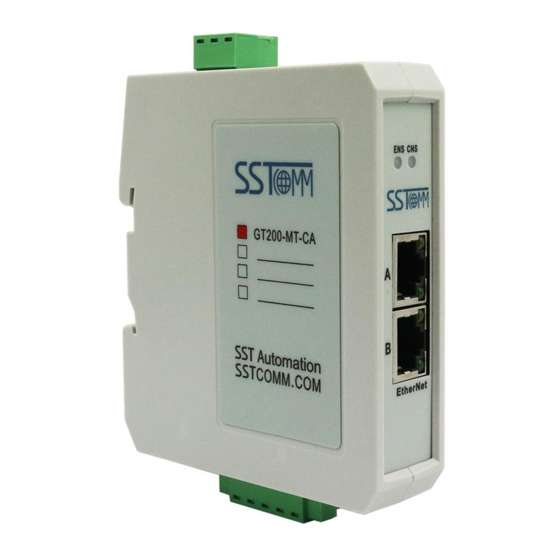
GT200-MT-CA EtherNet to CAN Gateway User Manual 3 Hardware Descriptions 3.1 Product Appearance 1. Power 2.DIP switch 4.CAN Status indicator 3. Ethernet Status Indicator 5.Ethernet port 6.CAN port 口 WWW.SSTCOMM.COM... -
Page 9: Indicators
GT200-MT-CA EtherNet to CAN Gateway User Manual 3.2 Indicators 3.2.1 Modbus TCP The indicator light is shown in the following table: Table 1 Modbus TCP status indicator Indicators Status Descriptions Green On Modbus TCP connection has been established Modbus TCP connection has not been... -
Page 10: Tcp Client
GT200-MT-CA EtherNet to CAN Gateway User Manual ENS (Orange) and CNS (Orange) (Orange: Red and green Blink alternately Configuration Mode light on at the same time) Blink ENS red, CNS red Simultaneously Using locate function three times Configuration Mode: After power on, the ENS and CNS orange light on simultaneously, and then flashes alternately, showing the gateway is in the state of configuration;... -
Page 11: Udp
GT200-MT-CA EtherNet to CAN Gateway User Manual 3.2.4 UDP The indicator light is shown in the following table: Table 4 UDP status indicator Indicators Status Descriptions Green on UDP normal (Ethernet status Red on status DHCP indicator) Red on CAN network error... -
Page 12: Ethernet Interface
GT200-MT-CA EtherNet to CAN Gateway User Manual Notes: Here, shield port is optional. The CAN-L and CAN-H must be connected. Here pin 1 and 5 are connected to the pin 3 and pin 1 of power port internally. Attention: here only one interface of 24V interface and power interface is required to connect, but should not be connected simultaneously. -
Page 13: Power Interface
User Manual Notes: After re-configuring DIP switch, you must restart the gateway GT200-MT-CA (power off and power on) to let the configuration take effect! After configuration is done, it is suggested to set the DIP switch to 0 1(run mode, prohibit remote configuration). -
Page 14: Quick Start Guide
Double click the installation package and install the configuration software 4.3 Communication Debugging 1.Please connect the Ethernet port to PC when GT200-MT-CA is first used, and turn the DIP switch to 2ON1OFF(configuration mode), then power on the module. The IP address should be 192.168.0.10. The segment of the PC should match with 192.168.0.X. -
Page 15: Software Configuration
GT200-MT-CA EtherNet to CAN Gateway User Manual 5 Software Configuration 5.1 Precautions 1. Please set the DIP switch (bit 2) to ON as the product is used for the first time, and configure the parameters in the static configuration. Noted the IP conflict will cause the start-up failure of the product. -
Page 16: Configuration
GT200-MT-CA EtherNet to CAN Gateway User Manual Figure 2: Device discovered The list shows the device information, including the "serial number", "type", "IP address", "MAC address", etc. 5.2.3 Configuration Select a device in the List, and then the "Locate", "Remote Reset" and "Configuration" becomes available, otherwise disabled. -
Page 17: Configure Ethernet Parameters
GT200-MT-CA EtherNet to CAN Gateway User Manual Figure 4: Ethernet configuration information 5.2.4 Configure Ethernet Parameters Ethernet parameters include "Type of Protocol", "Assign IP Mode", "IP Address", "Subnet Mask", "Gateway Address", "DNS1" and "DNS2" etc. WWW.SSTCOMM.COM... - Page 18 GT200-MT-CA EtherNet to CAN Gateway User Manual Figure 5: Ethernet configuration information Figure 6: CAN configuration information Type of Protocol —— Select the appropriate protocol type Assign IP Mode —— Set IP address configuration mode of the device; WWW.SSTCOMM.COM...
-
Page 19: Open / Save Configuration
GT200-MT-CA EtherNet to CAN Gateway User Manual IP Address —— Set the IP address of the device; Subnet Mask —— Set the subnet mask of the device; Default Gateway —— Set the gateway address of the device; DNS1 —— Primary Domain name server (may not be set in LAN );... -
Page 20: New
GT200-MT-CA EtherNet to CAN Gateway User Manual Figure 8: Save/Export file Note: User can change configuration data, after that users can save the parameters into file, but please ensure the accuracy of the data; otherwise incorrect data will be processed according to the default values. Please do not change the data in a keyword, and do not add spaces. -
Page 21: Ip Search
GT200-MT-CA EtherNet to CAN Gateway User Manual Figure 9: New Note: the new function is mainly used for off-line configuration, namely: configuration interface can also be opened without device in initialization parameters. 5.2.7 IP Search “IP Search” can search specified device by IP address, thereby configure this device. At this time, it only lists the device using the IP address. -
Page 22: Locate
User Manual 5.2.8 Locate Figure 11: Locate When selecting a device, locate function is available (otherwise disabled), click “Locate”, then ENS and CNS red lights will blink three seconds to locate the currently selected GT200-MT-CA equipment. 5.2.9 Remote Reset WWW.SSTCOMM.COM... - Page 23 GT200-MT-CA EtherNet to CAN Gateway User Manual Figure 12: Remote Reset Click the "remote reset" button, as shown in the pop-up interface above. Click on "OK", then execute remote reset operation, the gateway will restart (power off and power on). Click on "Cancel", and then cancel the reset operation.
-
Page 24: Working Principle
GT200-MT-CA EtherNet to CAN Gateway User Manual 6 Working Principle 6.1 Modbus TCP/CAN 6.1.1 Data Exchange The receiving and sending of CAN frame is FIFO. 6.1.2 The Relationship between Them The following is how to encapsulate a CAN frame with 16-byte (8 registers) a) Modbus TCP input register Use function code 04 to read the Modbus input register, that is CAN receive data. - Page 25 Users decide whether to use these CAN frame according to the needs. b) Modbus TCP output register Use function code 16 to write the data to Modbus output register of GT200-MT-CA, that is the CAN frame needs to send. The starting address is 0.
-
Page 26: Tcp Server/Tcp Client/Udp To Can
GT200-MT-CA EtherNet to CAN Gateway User Manual Byte 7: Bit 7 Bit 6 Bit 5 Bit 4 Bit 3 Bit 2 Bit 1 Bit 0 Meaning The lowest 8 bits of frame header Byte 8 to 15 are the CAN frame data, if the data number of CAN frame is less than 8 bytes, then it is 0. - Page 27 CAN frame to CAN frame header automatically. At this point, the CAN frame that GT200-MT- CA forwarding to Ethernet is 17 bytes long frame with time stamp. Additionally, GT200-MT-CA applies 13 bytes long CAN frame without times tamp) Control byte: occupies one byte including the extended frame signs, remote frame flag and the frame data length;...
-
Page 28: Terminal Resistor
GT200-MT-CA EtherNet to CAN Gateway User Manual when data lacks 8 bytes. Such as data string 12H, 34H, 56H, 78H, as the following format: 6.3 Terminal Resistor Under high baud rates (1M, 500k) situation, CAN network require each of two endpoints in the farthest networks to connect terminal resistor of 120ohm. -
Page 29: Installation
GT200-MT-CA EtherNet to CAN Gateway User Manual 7 Installation 7.1 Machine Dimension Size: 0.98 in (width)*3.94 in (height)*3.54 in (depth) WWW.SSTCOMM.COM... -
Page 30: Installation Method
GT200-MT-CA EtherNet to CAN Gateway User Manual 7.2 Installation Method Using 35mm DIN RALL Install and Remove the gateway as follows: Install the gateway Unload the gateway WWW.SSTCOMM.COM... -
Page 31: Operation Maintenance And Cautions
GT200-MT-CA EtherNet to CAN Gateway User Manual 8 Operation Maintenance and Cautions Prevent great pressure or it will damage the panel. Prevent collision or it may damage the inside elements. Supply voltage is DC 9V-30V; it must be controlled within the range of manual demand to prevent the ...
Need help?
Do you have a question about the GT200-MT-CA and is the answer not in the manual?
Questions and answers