
Related Manuals for SST Automation GT200-EI-CO


Summary of Contents for SST Automation GT200-EI-CO
- Page 1 CANopen / Ethernet Gateway GT200-EI-CO User Manual V 2.2 SST Automation E-mail: SUPPORT@SSTCOMM.COM WWW.SSTCOMM.COM...
- Page 2 The product has many applications. The users must make sure that all operations and results are in accordance with the safety of relevant fields, and the safety includes laws, rules, codes and standards. Copyright Copyright © 2020 by SST Automation. All rights reserved. Trademark is the registered trade mark of SST Automation.
-
Page 3: Table Of Contents
Catalog 1 Product Overview..............................1 1.1 Product Function.............................1 1.2 Product Feature............................... 1 1.3 Technical Specifications..........................1 1.4 Related Products............................. 2 1.5 Revision History............................. 2 2 Hardware Descriptions.............................. 3 2.1 Product Appearance............................3 2.2 LED Indicators..............................4 2.3 Configuration Switch/Button..........................4 2.4 Interface................................5 2.4.1 Power Interface............................ -
Page 4: Product Overview
1 Product Overview 1.1 Product Function The gateway supports connecting CANopen devices to EtherNet/IP network. That is, convert the devices on the CANopen network to EtherNet/IP network devices. 1.2 Product Feature Supports one channel CAN 2.0A; CAN interface: 3KV photoelectric isolation; ... -
Page 5: Related Products
Supports TPDO time-out reset; Supports NMT management; Supports SYNC function; Supports Guard life function; Supports RPDO cycle sending function; Supports CANopen master delay to start-up function; Supports Control Status function; Supports changing VendCode. [5] Operating environment: ... -
Page 6: Hardware Descriptions
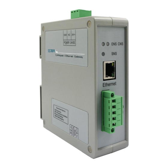
2 Hardware Descriptions 2.1 Product Appearance 24VDC Interface CANopen Status Indicator EtherNet/IP Status Indicator Ethernet Interface CAN Interface DIP Switch Notes: This picture is for reference only. The product appearance is subject to the actual product. WWW.SSTCOMM.COM... -
Page 7: Led Indicators
2.2 LED Indicators State State description Green On EtherNet/IP connection established Green Blinking EtherNet/IP connection is not established Indicates an IP address conflict EtherNet/IP connection timed out Red Blinking BOOTP Checking whether the IP address conflicts Orange light Blinking (Blinking alternately Configuration status with the orange light of CNS) -
Page 8: Interface
192.168.0.10, only can read and write configuration data BootLoader mode, with fixed IP address 192.168.0.10 Notes: After changing the switch, you have to restart the GT200-EI-CO to make the settings take effect! 2.4 Interface 2.4.1 Power Interface 24V+ Function... -
Page 9: Can Port
The Ethernet interface is a RJ-45 socket. Signal description TXD+, Tranceive Data+, Output TXD-, Tranceive Data-, Output RXD+, Receive Data+, Input Bi-directional Data+ Bi-directional Data- RXD-, Receive Data- Bi-directional Data+ Bi-directional Data- 2.4.3 CAN Port 5-pin connector: CAN-L CAN-H Shield The gateway uses open five-pin connector at the side of CAN: Connection V+ (Optional) -
Page 10: Mounting
3 Mounting 3.1 Mechanical Dimensions Size: 1.57 in * 4.92 in * 4.33 in (width * height * depth) 3.2 Mounting Method Use 13.8 in (35 mm) DIN Rail. WWW.SSTCOMM.COM... - Page 11 Install the gateway Uninstall the gateway WWW.SSTCOMM.COM...
-
Page 12: Quick Start Guide
IP in the configuration state. When the user chooses to use BOOTP, the user must use BOOTP Server to allocate IP in the running state. The default IP of GT200-EI-CO in configuration mode is 192.168.0.10, and users can connect GT200-EI-CO and PC in two ways: 1. -
Page 13: Operation
2. Connect GT200-EI-CO, PC and Ethernet router (gateway, Hub, switch) with straight-through network cable, as shown below: Note: In the configuration mode, the IP address of the PC must be changed to 192.168.0.x; The subnet mask must be changed to 255.255.255.0; The default gateway must be changed to 192.168.0.1. - Page 14 GT200-EI-CO supports Clear Data Time for TPDO: As long as GT200-EI-CO does not receive the TPDO from the slave within the set time, GT200-EI-CO will clear the data in corresponding position of the EtherNet/IP input buffer.
-
Page 15: Gateway Ethernet/Ip Connection Parameters
4.4.2 Gateway EtherNet/IP Connection Parameters The connection parameters provided by the gateway are as follows: Number Input Instance Output Instance Configuration Instance 112(132Bytes) 111(128Bytes) 113(10Bytes) 122(260Bytes) 121(256Bytes) 123(10Bytes) 132(68Bytes) 131(64Bytes) 133(10Bytes) 142(36Bytes) 141(32Bytes) 143(10Bytes) 152(20Bytes) 151(16Bytes) 153(10Bytes) 162(12Bytes) 161(8Bytes) 163(10Bytes) 172(504Bytes) 171(504Bytes) 173(10Bytes) -
Page 16: Software Instructions
5 Software Instructions SST-ECO-CFG is based on Windows platform. It is used to configure parameters and commands of GT200-EI-CO. This manual describes the method of configuring the gateway GT200-EI-CO. Please read the manual carefully before using it. 5.1 Notes Before Configuration If it is the first time to use the product, please set the configuration DIP switch (mode 1) to on, and configure the product parameters under static configuration. -
Page 17: Software Function
5.2 Software Function 5.2.1 User Interface Menu Bar Title Bar Toolbar Configuration plate: Input configuration parameters, gray parts cannot be changed Device plate: Users can select operation objects including Industrial EtherNet and CANopen Network, and adding nodes and commands Comment plate: Explain the function of the configuration options 5.2.2 Toolbar... -
Page 18: New Configuration Project
Open: Open a configuration project Save: Save current configuration Add Node: Add a CANopen node Delete Node: Delete a CANopen node Add Command: Add a CANopen command Delete Command: Delete a CANopen command Upload: Read the configuration information from the module and show it in the software Download: Download the configuration file to the gateway Calculate Mapping Address: To check whether there are some conflicts with configured commands in the gateway memory data buffer... -
Page 19: Open And Save Configuration
5.2.4 Open and Save Configuration Select "Open", you can open the configuration project that you have saved. Select "Save" or "Save as", you can save the configuration project with .chg as its extension. WWW.SSTCOMM.COM... -
Page 20: Upload And Download
Click icon on the tool bar you can save the configuration with .xls as its extension. Note: After saving the parameters as a file, the data in the file can be changed by the user , but please ensure the correctness of the changed data, otherwise the incorrect data will be processed according to the default value. -
Page 21: Industrial Ethernet Configuration Parameters
Note: The IP address is fixed at 192.168.0.10 in GT200-EI-CO configuration mode 5.2.6 Industrial Ethernet Configuration Parameters The Industrial Ethernet configuration interface is shown as below: In the above parameters, the detailed information is shown as below: Assign IP Mode: Manual configuration and BOOTP optional. -
Page 22: Canopen Configuration Parameters
Subnet Mask: Subnet mask of GT200-EI-CO. Gateway Address: Gateway address GT200-EI-CO is located in LAN. VendCode: Users can change VendCode, default is 1376. 5.2.7 CANopen Configuration Parameters Configure CANopen network parameters including Type of Protocol. CANopen Baud Rate, CANopen Node ID, SDO Response Timeout, Enable NMT, Clear Data Time for TPDO, SYNC Cycle, Guard life, The Cycle for RPDO Transmission, Delay to Start up, and Control&... -
Page 23: Device View Interface
5.2.8 Device View Interface 5.2.8.1 Device View Interface 5.2.8.2 Operation Mode Supports three kinds of operation modes: edit menu, edit toolbar, and right-click edit menu. WWW.SSTCOMM.COM... - Page 24 5.2.8.3 Operation Types Add node: Left click on CANopen Networks or existing nodes, and then perform the operation of adding a new node. Then there is a new node named "New node" under CANopen Network (The newly added node has no address.
- Page 25 Delete command: Left click a command and you can delete it. Copy node: Left click on the existing node, choose the node and execute the operation of copying nodes (include all commands under the node). Paste node: Left click and choose any existing node, execute operation of pasting node. Then under the ...
- Page 26 CANopen Baud Rate: 50K, 100K, 125K, 250K, 500K, 1M can be selected; the default value is 250K. CANopen Node ID: 1 to127, the default value is 127. SDO Response Timeout: This parameter is based on 10 milliseconds. The range of the parameter value is 1 ...
- Page 27 the mode of change of value output; non-zero means to send all RPDO according to the cycle. Sending cycle equals setting value, the default value is 0. The range: 0~60000. Note: This parameter and CAN baud rate are relevant with RPDO command numbers. If the system focuses on real-time performance, it is recommended to set this value to 0, that is, change of value output.
- Page 28 Slave address: CANopen slave address, the range is 1 to 127. Index value: Object index value in object dictionary (decimal). Sub-index value: Object sub-index value in object dictionary (decimal). Number of bytes: Number of bytes of mapping item. ...
- Page 29 Max Download SDO commands ≤ 128; 5.2.8.6 Comment Interface Comment interface displays the explanation of relevant configuration item. When the configuration item is "Index value", the comment interface is shown as below: 5.2.8.7 View device information View the basic information of the currently connected device, including: device serial number, production date, firmware version number, hardware version number, IP address.
Need help?
Do you have a question about the GT200-EI-CO and is the answer not in the manual?
Questions and answers