SST Automation GT200-HT-MT User Manual
Hart/modbus tcp gateway
Hide thumbs
Also See for GT200-HT-MT:
- User manual (74 pages) ,
- User manual (64 pages) ,
- User manual (89 pages)

Related Manuals for SST Automation GT200-HT-MT


Summary of Contents for SST Automation GT200-HT-MT
- Page 1 HART/ Modbus TCP Gateway GT200-HT-MT User Manual V 1.2 REV A SST Automation E-mail: SUPPORT@SSTCOMM.COM WWW.SSTCOMM.COM...
-
Page 2: Table Of Contents
3.4 Interface................................ 13 3.4.1 Power Interface..........................13 3.4.2 Ethernet Interface..........................14 3.4.4 HART Interface..........................14 3.5 Topology of GT200-HT-MT and Fieldbus Devices..................15 4 Software Instructions............................... 17 4.1 Software Interface Description........................17 4.2 Software Functional Specifications......................20 4.2.1 Configure the Fieldbus........................20 4.2.2Configure the HART Fieldbus......................20... - Page 3 5.3 Trigger Command............................43 5.4 Data Exchange with Modbus TCP....................... 44 6 Installation................................45 6.1 Machine Dimension............................45 6.2 Installation Method............................45 WWW.SSTCOMM.COM...
-
Page 4: Product Overview
1 Product Overview 1.1 Product Function GT200-HT-MT is a gateway that can exchange data between HART and Modbus TCP. HART interface can be configured as a primary master or a secondary master. Modbus TCP side acts as a slave. 1.2 Product Features Simple to use: users can refer to product manuals and application case to achieve communication in a short ... -
Page 5: Safety And Explosion-Proof Features
[13] Installation: 1.38 in (35mm) DIN RAIL [14] Protection Level: IP20 1.4 Safety and Explosion-Proof Features GT200-HT-MT is not the product with the features of safety and explosion-proof, please put it in the control room when using. 1.5 Related Products The related products include: GT200-3HT-RS and GT200-HT-DP etc. -
Page 6: Quick Start Guide
2 Quick Start Guide The following example introduces the use of the Gateway. 2.1 Configuration of Gateway 2.1.1 Pre-configured Settings Turn gateway's "mode" DIP switch to "ON" and "function" DIP switch to "OFF" Use crossed network cable to connect the gateway's Ethernet port (RJ45 interface) with that of computer; Power on the gateway, now the IP address of the gateway is fixed: 192.168.0.10 and it is configurable. - Page 7 4. Click "OK"; Select the gateway and Sign in the popup "Search Equipment" dialog box; 5. Select the "Fieldbus" in the tree view on the left, configure as below in the right interface; 6. Click the channel in the tree view on the left, the table appearing on the right is configured as below: WWW.SSTCOMM.COM...
- Page 8 Note: In the HART protocol, it specifies that the device with slave address 0 works under single point mode, it allows digital communication and analog communication exist at the same time. The device with slave address 0~15 works under the multipoint mode, the analog output of the device is the minimum value (4mA) and it only allows digital communication.
- Page 9 9. Click "Command ID1", the configuration table on the right is configured as below: 10. Click the icon , in the pop-up dialog box, select the Ethernet port with which gateway is connected to the computer, and then click Download: WWW.SSTCOMM.COM...
-
Page 10: Function Demo
2.2 Function Demo The HART interface of the gateway GT200-HT-MT connects with a 2-wire pressure transmitter with slave address 0. The Ethernet port is connected to the PC through network cable. The configured Modbus POLL software in PC can simulate to work as a Modbus TCP master, and then you can see the main variable value of the pressure transmitter in data exchange window: WWW.SSTCOMM.COM... -
Page 11: Hardware Descriptions
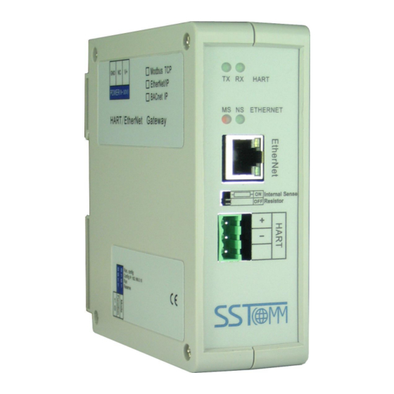
3 Hardware Descriptions 3.1 Product Appearance Status indicators 24VDC Interface Ethernet interface Switch of sampling resistor HART Interface DIP Switch Note: This picture is for reference only. Product appearance should refer to the real object. WWW.SSTCOMM.COM... -
Page 12: Indicators
Run mode, disable read/write the configuration data Configuration mode, IP address is fixed: 192.168.0.10, User can read/write the configuration data Reserved Note: After re-configuring the switch, you have to restart the GT200-HT-MT to make the settings take effect! (Power off then Power On) WWW.SSTCOMM.COM... -
Page 13: Internal / External Sampling Resistor Switch
3.3.2 Internal / External Sampling Resistor Switch GT200-HT-MT can choose using the internal sampling resistor or external sampling resistor to get the HART signal. The specification of the internal resistor is 270Ω, 2W. When the power of the sampling resistor is more than 2W, you must use an external resistor. -
Page 14: Ethernet Interface
3.4.2 Ethernet Interface Ethernet interface uses RJ-45 plug-in; its pin (standard Ethernet signal) is defined as below: Signal description TXD+, Tranceive Data+, Output TXD-, Tranceive Data-, Output RXD+, Receive Data+, Input Bi-directional Data+ Bi-directional Data- RXD-, Receive Data-, Input Bi-directional Data+ Bi-directional Data- 3.4.4 HART Interface HART Channel... -
Page 15: Topology Of Gt200-Ht-Mt And Fieldbus Devices
3.5 Topology of GT200-HT-MT and Fieldbus Devices WWW.SSTCOMM.COM... - Page 16 Note: 1. Some HART slave instrument need to perform self-test and other internal work when power is on, they may not start HART communication, then gateway cannot receive the response data of the instrument right now. It is recommended the HART slave instrument and gateway uses separate power supply so that the gateway can immediately establish communication with instrument.
-
Page 17: Software Instructions
SST-HE-CFG is configuring software based on Windows platform and it is used to configure HART series products of gateway. The following describes how to use the software SST-HE-CFG to configure the product GT200-HT-MT. Double-click on the icon to enter the main interface of software:... - Page 18 The function from left to right is: New, Save, Open, AddChannel, DelChannel, AddNode, DelNode, AddCmd, DelCmd, Upload, Download, AutoMap, Conflict, Export, Memory, Diagnose, Debug and Mode Switch. GT200-HT-MT doesn't support function of "Memory", "Diagnose", "Debug" and "Mode switch" temporarily. New: Create a new configuration file...
- Page 19 Export: Output current configuration to the local hard disk and saved as Excel spreadsheet form Memory: Show the data exchange situation inside of the gateway. GT200-HT-MT doesn't support this function temporarily. Diagnose: through this function could analyze operating condition of fieldbus device; also it can finish some certain analysis.
-
Page 20: Software Functional Specifications
It is shown below: Here user can configure some parameters: IP setting mode: Static configuration, BOOTP, DHCP optional; IP address: Set the IP address of GT200-HT-MT; Subnet mask: Set the subnet mask of device; Gateway address: Set the gateway address of device;... - Page 21 Master type: Primary master, Secondary master Network mode: Select the networks link as single or multiple points, under the single point the gateway can only communicate with the slave device whose address is 0; Select times of command resending, range: 0~5 Maximum repetitions: Enable Polling: Whether to use polling function, "Enable"...
- Page 22 Click the added node, set slave address in the right configuration plate, and please notice that HART channel can only be equipped with one slave node whose address is 0. Note: When configured node numbers are more than the actual connected devices, the redundant node will lead to the longer time of polling circle;...
- Page 23 Choose the command you want to add in the popup dialog box, and then click "OK" to exit: Note: the same command can only be configured once in one node. 4.2.2.4 Configure Slave Commands Click the command ID in the tree view; you will see the configuration plate of command in the right place: WWW.SSTCOMM.COM...
- Page 24 Mode of outputting command: You can use the execution way of the command, change-of-state, polling output, Initialization output and disable output optional; Change-of-state output: Execute this command once s data buffer of HART changes Polling output: This order is put in the polling list, executed periodically ...
- Page 25 4.2.2.6 Delete Nodes Select the node needed to be deleted, Right click the mouse and click "Delete Node". Through the menu command can also be the same action. 4.2.2.7 Advanced Options to Configure Slave Commands When using HART command configuration, sometimes users want to get one part data of one command. For example, No.1 HART command.
- Page 26 First to explain the "Mapped Address": Bytes: response bytes of "Response Data"; Memory Address: assigned memory address which this byte is located in memory buffer area of GT200-HT-MT; Modbus register address: the relevant Modbus register address of "Memory Address"; Note: this address is not a single address, which is the same memory area which it occupied.
-
Page 27: Conflict Detection
Choose "Byte0-3" and "Byte5-8", click auto mapping, as shown below: Close the dialog box, download the configuration into GT200-HT-MT. Others are the same with "Basic Mode". 4.2.3 Conflict Detection Conflict detection is used to check the distribution condition of the input and output data of all commands stored in the memory. -
Page 28: Automap
The left side is configuration commands, the right side is data memory address including receive data storage address and send data storage. Upper side is memory distribution of the HART's sending data; lower side is memory distribution of the HART's receiving data. When one memory unit is configured with two commands or more, the memory unit will display red color. -
Page 29: Upload Configuration
popup menu. 4.2.5 Upload Configuration Select the configuration interface: Show the "Ethernet Config" interface as below: When checking "Use the search function", it will search all identifiable hardware when the software is communicating with the hardware and will be shown in the device list: WWW.SSTCOMM.COM... - Page 30 Select the device, click "Sign in" to connect the device. When not checking "Use the search function", it will only search appointed hardware and only show this hardware in the device list. Click the upload icon again, pop up the dialog box below: ...
-
Page 31: Download Configuration
EtherNet/IP side. Steps are as follows: 1. Ensure that the GT200-HT-MT's function bit of DIP switch is in the ON state and the mode bit of DIP switch is in the OFF state, restart the gateway. GT200-HT-MT is in the run mode. - Page 32 "SST-HE-CFG", Click "Tool—Select Mode" and choose debug mode and then click on the icon , you can also click to choose debug mode. Choose the correct gateway in the device scanning window, interface is as follows: As is shown in the table, upper table shows the memory distribution of HART input data, lower table shows the output data.
-
Page 33: Diagnose
HART device data. The steps are as follows: 1) First, dial the DIP switch of GT200-HT-MT to "1OFF2OFF", then power on again. At this moment GT200-HT-MT is in running mode. - Page 34 3) Click "Upload Data" to pop up the following picture: 4) Click "OK" to enter the diagnostic interface: WWW.SSTCOMM.COM...
- Page 35 Click "Channel 1" in this interface, the right side of the gateway will display the status of the HART bus section, click "Update" will refresh the data once, click "Reset" will clear the system status, click " periodically refresh", the software will update the data in 500ms. 5) Click Node (x) appears below: This screen shows the response status of the configured command.
-
Page 36: Switching Tools
Click "Update" to update the data, "Edit" in the read-only command does not work. 4.2.9 Switching Tools In the "Tools" menu, there are two practical tools: They are used to switch between IEEE754 and PACKED ASCII conveniently. WWW.SSTCOMM.COM... - Page 37 WWW.SSTCOMM.COM...
-
Page 38: Working Principle
5 Working Principle The gateway internally opens up a length of 8156 bytes of memory as input and output buffers which exchange data. 0 ~ 4999 memory is used as the storage area of the HART input data and output data. 5000~8155 memory is used as the storage area of the status of three HART channel and control variables. - Page 39 status of Device15 _cmd0 5340-543 980-1059 340-439 The response status of user command 5440 1060-1195 Reserved 5440 1196H Universal receive label 5441 1196L Universal receive error counter 5442-544 1197 442-443 Universal receive data length 5444-574 1198-1347 444-743 Universal receive data 2696-299 Reserved 3000-399...
- Page 40 internally will automatically execute the No. 0 command to obtain the device information (to obtain the long address). The response data of this internal command is stored in this area. Gateway status: The gateway status indicates the state of the gateway in the HART network, defined as: ...
- Page 41 Trigger label: Changing the value will result in a trigger operation Trigger command number: Command number executed by trigger operation Universal mode enabled: The value 1 indicates a universal transfer function is enabled, otherwise disables universal transfer function Universal send label: The send label under the universal model, this value changes in time will lead to send a ...
-
Page 42: Flowchart Of Executing One Hart Command
5.1 Flowchart of Executing One HART Command Current command Initialization Input Data Output Data output Data State Data Satisfy the Execute Quit polling output command Slave's Sent to the slave response command frame Satisfy Change of state output Field instruments The next Meet the command... - Page 43 06H command "common mode enable" bit is 1 10H command will write the data to a continuous region which address begins from "Universal mode send data" The length of the data written to "The universal send data length" address with 06H command 06H command to change "the Universal send data label"...
- Page 44 5.4 Data Exchange with Modbus TCP When fieldbus is configured as "Modbus TCP", user can exchange data, inquire about the status of gateway and manage according to the corresponding address of gateway in the internal input and output buffer; Also you can do some trigger operation and transmission of universal frame.
- Page 45 6 Installation 6.1 Machine Dimension Size: 1.57 in (width)*4.92 in (height)*4.33 in (depth) 6.2 Installation Method Using 1.38 in (35mm) DIN RAIL WWW.SSTCOMM.COM...
- Page 46 Installing the gateway Unloading the gateway WWW.SSTCOMM.COM...
Need help?
Do you have a question about the GT200-HT-MT and is the answer not in the manual?
Questions and answers