
Subscribe to Our Youtube Channel
Related Manuals for Insignia NS-STV3N1705


Summary of Contents for Insignia NS-STV3N1705
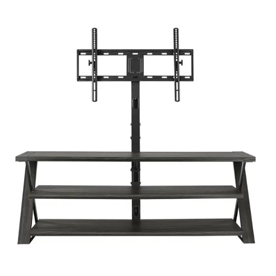
- Page 1 ASSEMBLY GUIDE 3-in-1 60 in. TV Stand NS-STV3N1705 Before using your new product, please read these instructions to prevent any damage.
-
Page 2: Table Of Contents
Contents IMPORTANT SAFEGUARDS ................3 Features . -
Page 3: Important Safeguards
3-in-1 60 in. TV Stand IMPORTANT SAFEGUARDS WARNING Some steps are more easily handled with two adults. CAUTION The top surface of this TV stand is designed for use with a product weighing no more than 100 lbs. (45.36 kg) and having a width that permits it to sit evenly on the TV stand with no more than a one-inch overhang on each side of the shelf. -
Page 4: Features
Features • 60 in. (152.4 cm) tabletop holds most TVs up to 70 in. (177.8 cm) and 100 lbs. (45.36 kg) • Two additional 54 in. (137.16 cm) shelves house your DVD player, gaming consoles, cable box and more • 3-in-1 design lets you choose how to display your TV – on the tabletop, mounted with the stand or on the wall •... -
Page 5: Package Contents
3-in-1 60 in. TV Stand Package contents Parts A Top shelf (1) B Middle shelf (1) C Bottom shelf (1) D Left leg (1) E Right leg (1) F Spine assembly (1) G Top shelf support (1) H Swiveling bracket(1) I Mounting frame(1) J TV brackets (2) K Cable management wheels (2) -
Page 6: Tv Mounting Kit Hardware
LABEL TV STAND PART QTY. LABEL TV STAND PART QTY. Small flat washer Touch up pen 2 1/2” Lag bolt Tipping restraint hardware kit TV Mounting Kit Hardware LABEL TV MOUNT PART QTY. LABEL TV MOUNT PART QTY. M4 x 12 mm bolt M8 x 50 mm bolt M4 lock washer M4 x 30 mm bolt... -
Page 7: Tools Needed (Not Provided)
3-in-1 60 in. TV Stand Tools needed (not provided) Level Socket wrench with Phillips screwdriver a 1/2” socket Hammer Edge-to-edge Pencil 1/8” drill bit (for tipping restraint) stud finder 3/16” wood drill bit Power drill 7/16” masonry drill bit Note: DO NOT USE power tools unless they are explicitly identified in this manual as required for use during assembly. Power tools can damage the fasteners, hardware, and/or components. -
Page 8: Assembling Your Tv Stand
Assembling your TV stand Tip: Assemble your TV stand on a carpeted floor or the empty TV stand carton to avoid scratching it. Note: Do not fully tighten all bolts until you finish assembling all of the parts. After assembly, go back and fully tighten all bolts. - Page 9 3-in-1 60 in. TV Stand STEP 2: Attaching the top shelf support to the spine assembly and top shelf frame You need: G Top shelf support (1) R Small flat washer (3) W 4 mm hex wrench (1) M 5/8” bolt (3) Q Lock washer (3) 1 Align the top shelf support (G) with the center of the top shelf frame (A) and the spine assembly (F).
- Page 10 STEP 3: Attaching the middle shelf to the spine assembly You need: B Middle shelf (1) N 1” bolt (2) W 4 mm hex wrench (1) 1 Align the middle shelf (B) to the spine assembly (F) at a 90° angle. Make sure that the drilled holes on the shelf align with the threaded holes on the spine.
- Page 11 3-in-1 60 in. TV Stand STEP 4: Attaching the bottom shelf to the spine assembly You need: C Bottom shelf (1) N 1” bolt (2) W 4 mm hex wrench (1) 1 Align the bottom shelf (C) to the spine assembly (F) at a 90° angle. Make sure that the drilled holes on the shelf align with the threaded holes on the spine.
- Page 12 STEP 5: Attaching the right leg to the shelves You need: E Right leg (1) N 1” bolt (3) W 4 mm hex wrench (1) 1 Align and attach the right leg (E) to the shelf frames (A, B, and C). Make sure that the mounting holes on the shelf frame overlap the threaded sockets in the right leg (E), and that the metal pin on the top shelf frame (A) fits into the hole in the right leg (E).
- Page 13 3-in-1 60 in. TV Stand STEP 6: Attaching the left leg to the shelves You need: D Left leg (1) N 1” bolt (3) W 4 mm hex wrench (1) 1 Align and attach the left leg (D) to the shelf frames (A, B, and C). Make sure that the mounting holes on the shelf frame overlap the threaded sockets in the left leg (D), and that the metal pin on the top shelf frame (A) fits into the hole in the left leg (D).
- Page 14 STEP 7: Attaching the top shelf frame to both legs You need: N 1” bolt (4) Q Lock washer (4) R Small flat washer (4) W 4 mm hex wrench (1) 1 Place small flat washers (R) and lock washers (Q) over each of the metal brackets of the top shelf (A) at both ends. 2 Insert 1"...
-
Page 15: Mounting Your Tv Using The Swivel Configuration
3-in-1 60 in. TV Stand Mounting your TV using the swivel configuration Note: If you are wall mounting the TV, go to STEP 4: Selecting the correct bolts, washers, and spacers to mount your TV on page 18. CAUTION: This unit will only support a TV with a maximum weight of 100 lbs. (45.36 kg). STEP 1: Attaching the swivel bracket to the mounting frame You need: Q Lock washer (4) R Small flat washer (4) - Page 16 STEP 2: Attaching the swivel bracket assembly to the spine You need: M 5/8” bolt (6) Q Lock washer (6) R Small flat washer (6) W 4 mm hex wrench (1) Note: The upper spine provides four height options for your TV. Based on your TV size, adjust the swivel bracket (H) to the best height for optimum viewing.
- Page 17 3-in-1 60 in. TV Stand STEP 3: Attaching the cable wheels to the spine You need: K Cable management wheel (2) M 5/8” bolt (4) W 4 mm hex wrench (1) 1 Align a cable management wheel (K) with one of four possible locations on the spine assembly (F), then insert two 5/8” bolts (M) through the cable management wheel and into the spine.
- Page 18 STEP 4: Selecting the correct bolts, washers, and spacers to mount your TV To select the correct bolt, washer, and spacer size, try one of the bolts in one of the four VESA mounting holes on the back of your TV. A bolt that is too large will not fit in the hole at all, but make sure that the bolt size you choose is not too loose. It should grip the hole threads evenly and not wobble.
- Page 19 3-in-1 60 in. TV Stand STEP 5: Determine whether your TV has a flat back, an irregular or obstructed back, or a curved screen: 1 Carefully place your TV screen face-down on a cushioned, clean surface to protect the screen from damages and scratches.
- Page 20 STEP 6: Option 1 - Mounting the TV brackets on a TV with a flat back You need: AA M4 x 12 mm CC M5 x 12 mm SS M6 x 16 mm GG M8 x 16 mm HH M8 x 20mm EE M6 x 12 mm bolt (4) bolt (4)
- Page 21 3-in-1 60 in. TV Stand STEP 6: Option 2 - Mounting the TV brackets on a TV with an irregular or obstructed back or a curved screen You need: II M8 x 40 mm bolt JJ M8 x 50mm bolt FF M6 x 35 mm BB M4 x 30 mm DD M5 x 30 mm...
- Page 22 STEP 7: Attaching the TV to the mounting frame Note: If you are wall-mounting the TV, go to Mounting your TV using the wall-mount configuration on page 25. CAUTION: This unit will only support a TV with a maximum weight of 100 lbs. (45.36 kg). You need: Phillips screwdriver 1 With the help of another adult, lift the TV up to the mounting frame (I).
-
Page 23: Step 8: Adjusting The Tilt
3-in-1 60 in. TV Stand STEP 8: Adjusting the tilt You need: X 3/16” hex wrench (1) The TV brackets (J) let you make a tilt adjustment of up to 11° down and 5° up to provide optimum viewing and minimize glare. - Page 24 STEP 9: Positioning your TV stand and installing the tipping restraint hardware kit You need: Z Tipping restraint hardware kit(1) Edge-to-edge stud finder 1/8” drill bit Power drill Phillips screwdriver Level Pencil 1 Position your assembled stand against a wall where you plan to use it. 2 Adjust the leveling feet to level your TV stand.
-
Page 25: Mounting Your Tv Using The Wall-Mount Configuration
3-in-1 60 in. TV Stand Mounting your TV using the wall-mount configuration CAUTION: This unit will only support a TV with a maximum weight of 100 lbs. (45.36 kg). STEP 1: Removing the upper spine You need: W 4 mm hex wrench •... - Page 26 STEP 2: Inserting the end cap You need: V Spine end cap (1) • Insert the spine end cap (V) all the way into the top of the lower section of the spine (F). www.insigniaproducts.com...
- Page 27 3-in-1 60 in. TV Stand STEP 3: Attaching the cable management wheels You need: W 4 mm hex wrench M 5/8” bolt (4) K Cable management wheel (1) 1 Align a cable management wheel (K) with one of two possible locations on the lower spine (F), then insert two 5/8” bolts (M) through the cable management wheel and into the spine assembly.
- Page 28 STEP 4: Option 1 - Mounting the frame to a stud wall Note: If you are mounting the TV on a concrete or block wall, to go STEP 4: Option 2 - Mounting the frame to a block or concrete wall on page 29.
- Page 29 3-in-1 60 in. TV Stand STEP 4: Option 2 - Mounting the frame to a block or concrete wall You need: Level T Concrete anchor (4) Hammer S Lag bolt (4) 7/16” masonry drill bit Power drill Socket wrench with Pencil U Large flat washer (4) a 1/2”...
- Page 30 STEP 5: Attaching your TV to the mounting frame on the wall You need: Phillips screwdriver 1 Depending on the type of TV that you own, attach the TV brackets (J) to the back of the TV following the steps in: •...
- Page 31 3-in-1 60 in. TV Stand STEP 6: Adjusting the tilt You need: X 3/16” hex wrench (1) The TV brackets (J) let you make a tilt adjustment of up to 11° down and 5° up to provide optimum viewing and minimize glare.
-
Page 32: Mounting Your Tv Using The Tabletop Configuration
Mounting your TV using the tabletop configuration CAUTION: This unit will only support a TV with a maximum weight of 100 lbs. (45.36 kg). STEP 1: Removing the upper spine You need: W 4 mm hex wrench • Unscrew the four bolts and the washers on the spine (F), then remove the upper section of the spine from the spine assembly. - Page 33 3-in-1 60 in. TV Stand STEP 2: Inserting the end cap You need: V Spine end cap (1) • Insert the spine end cap (V) all the way into the top of the lower section of the spine (F). www.insigniaproducts.com...
- Page 34 STEP 3: Attaching the cable management wheels You need: W 4 mm hex wrench M 5/8” bolt (4) K Cable management wheel (2) 1 Align a cable management wheel (K) with one of two possible locations on the lower spine assembly (F), then insert two 5/8”...
- Page 35 3-in-1 60 in. TV Stand STEP 4: Positioning your TV stand and installing the tipping restraint hardware kit You need: Z Tipping restraint hardware kit(1) Edge-to-edge stud finder 1/8” drill bit Power drill Pencil Phillips screwdriver Level 1 Position your assembled stand against a wall where you plan to use it. 2 Adjust the leveling feet to level your TV stand.
-
Page 36: Maintaining Your Tv Stand
Maintaining your TV stand Wood/Laminate • Use your favorite type of furniture polish. • Do not spray polish directly onto the TV stand. Spray onto a soft cloth, then wipe the TV stand. • Always test any polish in a discrete location first, such as the back of the TV stand, to make sure that there is no adverse reaction. -
Page 37: One-Year Limited Warranty
During the Warranty Period, if the original manufacture of the material or workmanship of the Product is determined to be defective by an authorized Insignia repair center or store personnel, Insignia will (at its sole option): (1) repair the Product with new or rebuilt parts; or (2) replace the Product at no charge with new or rebuilt comparable products or parts. - Page 38 1-877-467-4289 (U.S. and Canada) or 01-800-926-3000 (Mexico) INSIGNIA is a trademark of Best Buy and its affiliated companies. Distributed by Best Buy Purchasing, LLC 7601 Penn Ave South, Richfield, MN 55423 U.S.A. V2 ENGLISH ©2024 Best Buy. All rights reserved.
Need help?
Do you have a question about the NS-STV3N1705 and is the answer not in the manual?
Questions and answers