Table of Contents
Advertisement
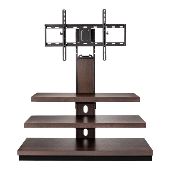
Wood Finish 3-in-1 TV
Stand
55"/135 lbs.
NS-HWMC1848
Before using your new product, please read these instructions to prevent any damage.
for TVs up to
Package Contents: Parts ..................................4
Package Contents: Hardware .......................5
Assembly Instructions ......................................7
Care And Maintenance ................................... 33
USER GUIDE
Advertisement
Table of Contents

Subscribe to Our Youtube Channel
Related Manuals for Insignia NS-HWMC1848


Summary of Contents for Insignia NS-HWMC1848
- Page 1 USER GUIDE Wood Finish 3-in-1 TV Stand for TVs up to 55”/135 lbs. NS-HWMC1848 SAFETY INFORMATION AND SPECIFICATIONS .2 PACKAGE CONTENTS: PARTS ........4 PACKAGE CONTENTS: HARDWARE .......5 ASSEMBLY INSTRUCTIONS ........7 CARE AND MAINTENANCE ........33 Before using your new product, please read these instructions to prevent any damage.
-
Page 2: Safety Information And Specifications
3-in-1 TV STAND SAFETY INFORMATION Maximum overall weight: 235 lbs (106.6 kg) AND SPECIFICATIONS Maximum top shelf weight: 135 lbs (61.2 kg) Maximum lower shelf weight: 50 lbs (22.6 kg) CAUTION: The top surface of this stand Maximum TV weight on swivel stand: 135 lbs is designed for use with a product weighing no more than (61.2 kg) -
Page 3: Tools Needed
3-in-1 TV STAND Tools needed: Phillips screwdriver Pencil Power drill Edge-to-edge stud finder 3/8” drill bit (for tipping restraint) Level 3/16” wood drill bit Hammer 1/2” Socket wrench 7/16” masonry drill bit www.insigniaproducts.com... -
Page 4: Table Of Contents
3-in-1 TV STAND PACKAGE CONTENTS: PARTS Make sure that you have all the parts necessary to assemble your new TV stand. C Long rear support (1) A Left side frame (1) B Right side frame (1) D Bottom crossbar (1) E Bottom left rail (1) F Bottom right rail (1) H Support leg (2) -
Page 5: Package Contents: Hardware
3-in-1 TV STAND PACKAGE CONTENTS: HARDWARE Note: You may receive extra hardware. Make sure that you have all the hardware necessary to assemble your new TV stand. Label Hardware Qty. Label Hardware Qty. Cable clip Flat washer Hex nut Screw #4 x 10 mm Bolt 1/2”... - Page 6 3-in-1 TV STAND PACKAGE CONTENTS: HARDWARE (continued) Label Hardware Qty. Label Hardware Qty. Bolt M8 × 50 mm Tipping restraint hardware kit Lock washer M4 Bolt M4 × 12 mm Lock washer M5 Bolt M4 × 30 mm Bolt M5 × 12 mm Lock washer M6 Bolt M5 ×...
-
Page 7: Assembly Instructions
3-in-1 TV STAND ASSEMBLY INSTRUCTIONS Step 1: Attach the back stretchers between the side frames Tip: Assemble your stand on a carpeted floor or the empty TV stand carton to avoid scratching it. 1 Insert four 1 5/8" bolts (U), with lock washers (W) and flat washers (X), through the drilled holes on the left side frame (A) and screw them into the threaded holes on the side of the back stretchers (G) with the 4 mm hex key (EE). - Page 8 3-in-1 TV STAND Step 2: Attach the back panel between the back stretchers • Using the pilot holes as guide, insert four 10 mm screws (R) through the metal brackets of the back stretchers (G) and securely screw them into the back panel (L) using a Phillips screwdriver. Pilot hole You’ll need: Phillips screwdriver...
- Page 9 3-in-1 TV STAND Step 3: Align and attach the top shelf to the side frames • Insert four 1 5/8” bolts (U), with lock washers (W) and flat washers (X), through the drilled holes on the top rails of both side frames (A and B), then securely screw them into the threaded holes on the top shelf (I) using the 4 mm hex key (EE).
- Page 10 3-in-1 TV STAND Step 4: Align and attach the middle shelf to the side frames • Insert four 1 5/8” bolts (U), with lock washers (W) and flat washers (X), through the drilled holes on the middle rails of both side frames (A and B), then securely screw them into the threaded holes on the middle shelf (J) using the 4 mm hex key (EE).
- Page 11 3-in-1 TV STAND Step 5: Attach the bottom subframe • Insert four 5/8” bolts (T), with lock washers (W) and flat washers (X), through the end brackets on the left and right rails (E and F), then securely screw them into the threaded holes on the bottom crossbar (D) with the 4 mm hex key (EE).
- Page 12 3-in-1 TV STAND Step 6: Attach the bottom subframe to the bottom shelf 1 Insert six 5/8” bolts (T), with lock washers (W) and flat washers (X), through the metal tabs on the bottom crossbar (D) and the side rails (E and F), then finger tighten them into the threaded holes on the bottom shelf (K).
- Page 13 3-in-1 TV STAND Step 7: Align and attach the bottom shelf to the side frames • Insert four 2 1/4” bolts (V), with lock washers (W) and flat washers (X), through the drilled holes on the bottom rails of both side frames (A and B), then securely screw them into the threaded holes on the bottom shelf (K) with the 4 mm hex key (EE).
- Page 14 3-in-1 TV STAND Step 8 Attach the support legs to the bottom shelf 1 Securely screw two support legs (H) into the threaded holes on the back rail of the bottom shelf (K). 2 Stand the assembled frame upright. NOTE: For swivel stand assembly, see “SWIVEL STAND ASSEMBLY INSTRUCTIONS”...
- Page 15 3-in-1 TV STAND Step 9 Attach the cable clips • Attach two of the cable clips (Q) to the back of the side frames (A and B) with two 5/8" bolts (T) per cable clip using the 4 mm hex key (EE). You’ll need: Q (2) T (4)
- Page 16 3-in-1 TV STAND FINAL TABLE TOP ASSEMBLY INSTRUCTIONS Step 10 Position the TV stand and install the tipping restraint hardware kit 1 Position the assembled stand against a wall where you plan to use it. 2 Adjust the leveling feet to level the TV stand. 3 Follow the instructions printed on the bag containing the tipping restraint hardware kit (GG) to attach the restraint hardware to the wall and the stand.
- Page 17 3-in-1 TV STAND WALL MOUNT ASSEMBLY INSTRUCTIONS Step 1: Select the correct bolts, washers, and spacers for your TV. If you are in doubt about which size bolt to use, try one of the bolts in one of the four Vesa mounting holes on the back of your TV.
- Page 18 3-in-1 TV STAND Step 2: Determine whether your TV has a flat back or an irregular or obstructed back or a curved screen 1 Carefully place your TV screen face-down on a cushioned, clean surface to protect the screen from damages and scratches.
- Page 19 3-in-1 TV STAND Step 3 Option 1 - Mounting bracket instructions for a TV with a flat back To mount the TV brackets: 1 Insert the selected bolts through the washers and proper mounting holes on the TV brackets (P) (for the 100 x 100 mm vesa pattern you’ll need to lift the bracket hangers to insert the screws), then finger tighten them into the threaded holes on the back of your TV.
- Page 20 3-in-1 TV STAND Step 3 Option 2 - Mounting bracket instructions for a TV with an irregularly shaped or obstructed back or curved screen TVs. 1 Insert the selected bolts through the washers and proper mounting holes on the TV brackets (P) (for the 100 x 100 mm vesa pattern you’ll need to lift the bracket hangers to insert the screws), then finger tighten them into the threaded holes on the back of your TV.
- Page 21 3-in-1 TV STAND Step 4 Option 1 - Mount the frame to a stud wall NOTE: See Step 4: Option 2 for instructions on mounting the frame to a concrete wall. 1 Use a stud sensor to locate two adjacent wall studs, then position the mounting frame (N) exactly between the two studs.
- Page 22 3-in-1 TV STAND Step 4: Option 2 - Mount the frame to a block or concrete wall 1 Place the mounting frame (N) against the wall where you intend to mount the TV. Use a level to make sure the mounting frame (N) is level, then mark the four mounting holes on the wall.
- Page 23 3-in-1 TV STAND Step 5 Attaching the TV to the mounting frame on the wall 1 Lift the TV up to the mounting frame (N). 2 Set the hooks on TV brackets (P) over the mounting frame, then lower the hooks onto the bars on the mounting frame.
- Page 24 3-in-1 TV STAND Step 6 Adjusting the tilt The TV brackets (P) allow you to make a tilt adjustment of up to 11° down and 5° up to provide optimum viewing and minimize glare. 1 Loosen the tension knobs on both TV brackets (P), then grasp the edge of the TV and move it up or down to the position you want.
- Page 25 3-in-1 TV STAND Step 7 Position the TV stand and install the tipping restraint hardware kit 1 Position the assembled stand against a wall where you plan to use it. 2 If necessary, adjust the leveling feet to level the TV stand. 3 Follow the instructions printed on the bag containing the tipping restraint hardware kit (GG) to attach the restraint hardware to the wall and the stand.
- Page 26 3-in-1 TV STAND SWIVEL STAND ASSEMBLY INSTRUCTIONS Step 1: Align and attach the long rear support • Insert four 2¼" bolts (V), with lock washers (W) and the flat washers (X), through the drilled holes in the long rear support (C), then securely screw them into the threaded holes of the side frames (A and B) with the 4 mm hex key (EE).
- Page 27 3-in-1 TV STAND Step 2: Attach the swivel bracket 1 Align the swivel bracket (M) at the height you would like the center of your TV to be. 2 Insert a 2¼” bolt (V), with a lock washer (W) and a flat washer (X), through the swiveling bracket (N) and the long rear support (C).
- Page 28 3-in-1 TV STAND Step 3: Attach the mounting frame to the swivel bracket 1 Hold the flat side of the mounting frame (N) against the swivel bracket (M), aligning the holes. Make sure that the two recessed holes on mounting frame (N) are at the bottom. 2 Insert a 1/2"...
- Page 29 3-in-1 TV STAND Step 4: Attach the cable clips • Attach the cable clips (Q) to the back of the long rear support (C) in two of four possible locations with two 5/8" bolts (T) per cable clip. You’ll need: EE (1) T (4) Q (2)
- Page 30 3-in-1 TV STAND Step 5 Attaching the TV to the mounting frame on the swivel bracket 1 Attach the TV brackets (P) to the back of the television following the steps on pages 18, 19, and 20, depending on the type of TV that you own. 2 Lift the TV up to the mounting frame (N).
- Page 31 3-in-1 TV STAND Step 6 Adjusting the tilt The TV brackets (P) allow you to make a tilt adjustment of up to 11° down and 5° up to provide optimum viewing and minimize glare. 1 Loosen the tension knobs on both TV brackets (P), then grasp the edge of the TV and move it up or down to the position you want.
- Page 32 3-in-1 TV STAND Step 7 Position the TV stand and install the tipping restraint hardware kit 1 Position the assembled stand against a wall where you plan to use it. 2 If necessary, adjust the leveling feet to level the TV stand. 3 Follow the instructions printed on the bag containing the tipping restraint hardware kit (GG) to attach the restraint hardware to the wall and the stand.
-
Page 33: Care And Maintenance
3-in-1 TV STAND CARE AND MAINTENANCE Wood/Laminate • Use your favorite type of furniture polish. • Do not spray polish directly onto the stand. Spray onto a soft cloth then wipe the stand. • Always test any polish in a discrete location first, such as the back of the stand, to make sure that there is no adverse reaction. - Page 34 DURATION TO THE WARRANTY PERIOD SET FORTH ABOVE AND Insignia and are not returned to you. If service of Products or NO WARRANTIES, WHETHER EXPRESS OR IMPLIED, WILL APPLY parts are required after the Warranty Period expires, you must AFTER THE WARRANTY PERIOD.
- Page 35 1-877-467-4289 (U.S. and Canada) or 01-800-926-3000 (Mexico) www.insigniaproducts.com INSIGNIA is a trademark of Best Buy and its affiliated companies. Registered in some countries. Distributed by Best Buy Purchasing, LLC 7601 Penn Ave South, Richfield, MN 55423 U.S.A. ©2017 Best Buy. All rights reserved.
Need help?
Do you have a question about the NS-HWMC1848 and is the answer not in the manual?
Questions and answers