
Related Manuals for GEA VARIVENT W R Series


Summary of Contents for GEA VARIVENT W R Series
- Page 1 Operating Instructions ® VARIVENT Shuttle Valve Type W_R Edition 19/09/2016 English...
- Page 2 EU Machinery Directive. This document is protected by copy- right. All rights reserved. The document may not, in whole or in part, be copied, reproduced, translated or reduced to an electronic medium of machine-readable form without the express permission of GEA Tuchenhagen GmbH. ® ®...
-
Page 3: Table Of Contents
Table of Contents Notes for the Reader ............................5 Binding Character of These Operating Instructions ..................5 Notes on the Illustrations ..........................5 Symbols and Highlighting ..........................6 Abbreviations and Terms ..........................7 Safety ................................9 Safety Note ............................... 9 Operator's Duties .............................. - Page 4 Valve with Detachable Pipe Connection Elements ..................26 Valve with Welding Ends..........................27 Pneumatic Connections ..........................28 • Air Requirement ............................28 • Establishing Hose Connections ........................28 Electrical Connections ............................. 29 Commissioning ..............................29 Cleaning and Passivation..........................30 Cleaning ................................30 •...
-
Page 5: Notes For The Reader
Notes for the Reader Notes on the Illustrations Notes for the Reader The present Operating Instructions are part of the user information for the valve. The Operating Instructions contain all the information you need to transport, install, commis- sion, operate and carry out maintenance for the valve. Binding Character of These Operating Instructions These Operating Instructions contain the manufacturer's instructions to the operator of the valve and to all persons who work on or use the valve regarding the procedures to... -
Page 6: Symbols And Highlighting
Notes for the Reader Symbols and Highlighting Symbols and Highlighting In these Operating Instructions, important information is highlighted by symbols or special formatting. The following examples illustrate the most important types of high- lighting. DANGER Warning: Fatal Injuries. Failure to observe the warning can result in serious damage to health, or even death. ... -
Page 7: Abbreviations And Terms
Notes for the Reader Abbreviations and Terms IMPORTANT NOTE Warning: Damage to Property. Failure to observe the warning can result in serious damage to the valve or in the vicinity of the valve. The arrow identifies a precautionary measure you have to take to avoid the hazard. Carry out the following steps: = Start of a set of instructions. - Page 8 Notes for the Reader Abbreviations and Terms Abbreviation Explanation HNBR Material designation Short designation according to DIN/ISO 1629: Hydrogenated Acrylonitrile Butadiene Rubber Protection class International standard issued by the International Organization for Standardi- zation Unit of measurement of weight [kilogram] Unit of measurement of force [kilonewton] Kv value Flow coefficient [m³/s]...
-
Page 9: Safety
Safety Operator's Duties Safety Safety Note The valve is operationally reliable. It was built according to state-of-the-art standards. Nevertheless, the valve can pose dangers, especially if • the valve is not used in accordance with its intended use, • the valve is not used correctly, •... -
Page 10: Qualification Of Staff
Safety Qualification of Staff Qualification of Staff This section contains information about the qualifications that staff working on the valve must have. Operating and maintenance staff must • have the necessary qualification to carry out their tasks, • be instructed with regard to possible dangers, •... -
Page 11: Supplementary Regulations
Safety Supplementary Regulations For work to be carried out on the valve the following user groups are distinguished: User groups Staff Qualifications Operating staff Adequate instruction and sound knowledge in the following areas: • Function of the valve • Valve operating sequences •... -
Page 12: Instructions For The Safe Operation
Safety Instructions for the Safe Operation Instructions for the Safe Operation Dangerous situations during the operation can be avoided by safety-conscious and proactive behaviour of the staff. General Principles To ensure the safe operation of the valve the following principles apply: •... -
Page 13: Commissioning/Setup Mode
Safety Instructions for the Safe Operation Commissioning/Setup Mode For commissioning, the following principles apply: • Take protective measures against dangerous contact voltages in accordance with pertinent regulations. • The valve must be completely assembled and correctly adjusted. All screw connec- tions must be securely tightened. -
Page 14: Shutting Down
Safety Instructions for the Safe Operation Shutting Down For shutting down, the following principles apply: • Switch off the compressed air. • Switch off the valve via the main switch. • Padlock the main switch (if fitted) in the off position to prevent it from being switched back on. -
Page 15: Disassembly
Safety Instructions for the Safe Operation Disassembly For disassembly, the following principles apply: • Only allow qualified staff to disassemble the valve. • Before starting disassembly, the valve must be switched off and secured against being switched back on. Work may only be started once any residual energy has been discharged. -
Page 16: Signage
Safety Signage Signage Dangerous points on the valve are indicated by warning signs, prohibition signs and mandatory signs. The signs and notes on the valve must always be legible. Any illegible signs must be replaced immediately. Signs on the valve Sign Meaning General hazard warning... -
Page 17: Residual Risk
Safety Residual Risk Residual Risk Hazard Areas Please observe the following notes: • In the event of malfunctions, shut down the valve (disconnect from the power and air supply) and secure it against being used. • Never reach into the lantern (9) or the valve housing (391) when the valve is switching. -
Page 18: Residual Dangers
Spring tension in the actu- Danger to life caused by compression spring in ator the actuator. Do not open the actuator but return it to GEA Tuchenhagen for proper disposal. Danger of injury Danger presented by The operator must exercise caution and moving or sharp-edged prudence. -
Page 19: Declaration Of Conformity
2006/42/EC Applicable harmonized standards: DIN EN ISO 12100 Authorised representative for compilation Authorised representative – of the technical documentation CE documentation GEA Tuchenhagen GmbH Am Industriepark 2-10 21514 Büchen Büchen, 16/02/2015 Franz Bürmann i.V. Matthias Südel Managing Director Team Leader Product Development... -
Page 20: Transport And Storage
Transport and Storage Transport Transport and Storage Scope of Supply On receipt of the valve check whether • the details on the type plate correspond to the data in the order and delivery docu- ments, • the equipment is complete and all components are in good order. Transport For transport, the following principles apply: •... -
Page 21: Storage
Transport and Storage Storage Storage The valves, valve inserts or spare parts should be stored in a dry place, free of vibra- tions and dust. To avoid damage, leave the components in their original packaging if possible. If, during transport or storage, the valve is going to be exposed to temperatures 0°C, it must be dried beforehand and suitable measures must be taken to protect it from damage. -
Page 22: Intended Purpose
Shuttle Valve Type W_R is a piece of pressure equipment (without safety function) in the sense of the pressure equipment directive: Directive 97/23/EC. It is classified according to Annex II, article 3, section 3. In the event of any deviations, GEA Tuchen- hagen GmbH will supply a special Declaration of Conformity. -
Page 23: Improper Operating Conditions
EC Machinery Direc- tive on your own. In general, only original spare parts supplied by GEA Tuchenhagen GmbH should be fitted. This ensures the reliable and economical operation of the valve. -
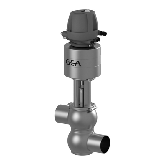
Page 24: Design And Function
Design and Function Design Design and Function Design Designation Designation Actuator Lantern Control top Valve disk Sealing ring Air connection Bearing Electrical connection Sealing disk Valve housing Bearing disk ® Operating Instructions · VARIVENT Shuttle Valve Type W_R Edition 19/09/2016... -
Page 25: Function
Design and Function Function Function Distinguishing Feature of Spring-To-Close Actuator (Z) The valve is closed in the non-actuated position. Identification: – Green steady light (1): valve in non-actuated position – Yellow steady light (1): valve in end position (actuated position) Distinguishing Feature of Spring-To-Open Actuator (A) The valve is open in the non-actuated position. -
Page 26: Installation And Commissioning
Installation and Commissioning Valve with Detachable Pipe Connection Elements Installation and Commissioning Notes on Installation The valve can be installed in any position. Care must be taken to ensure that the valve housing and the pipe system can drain properly. If the valve is installed in the horizontal position, pay attention that the vent hole in the actuator is aligned horizontally on one side. -
Page 27: Valve With Welding Ends
Installation and Commissioning Valve with Welding Ends Valve with Welding Ends This section describes the welding procedure for the valve. WARNING Spring tension in the valve Danger of injury when opening the clamp connections on the actuator or on the housing as the released spring pretension will suddenly lift the actuator. -
Page 28: Pneumatic Connections
Installation and Commissioning Pneumatic Connections Pneumatic Connections Air Requirement Actuator type Actuator Ø (mm) Air requirement /stroke) at 1.01325 bar at 0°C as per DIN 1343 A... 0.16 DN 25 - DN 100 1" - 4" OD, 2" - 4" IPS B... -
Page 29: Electrical Connections
Installation and Commissioning Commissioning Electrical Connections DANGER Live parts Electrical shock can result in serious personal injury or death. Only allow properly qualified staff to carry out work on the electrical equipment. Prior to establishing electrical connections check the maximum permissible oper- ating voltage. -
Page 30: Cleaning And Passivation
Cleaning and Passivation Cleaning Cleaning and Passivation Cleaning All parts in contact with product must be cleaned at regular intervals. Always observe the safety data sheets issued by the cleaning agent manufacturers. Only use cleaning agents which do not cause damage to the seals and the inner parts of the valve. When the pipe is cleaned, the cleaning medium also flows through and cleans the valve hous- ings. -
Page 31: Cleaning Effect
Cleaning and Passivation Passivation Cleaning Effect The cleaning effect depends on the following factors: • Temperature • Time • Mechanics • Chemicals • Degree of soiling These factors can be combined in such a way as to make an optimal cleaning result probable. -
Page 32: Malfunctions
Malfunctions Malfunctions In the event of malfunctions immediately deactivate the valve and secure it against inad- vertent reactivation. Malfunctions may only be remedied by qualified staff, who must observe the safety instructions. Malfunction Cause Remedy Valve does not work Fault in the control system Check the system configura- tion No compressed air or... -
Page 33: Maintenance
Maintenance Inspections Maintenance Inspections Between the maintenance periods, the valves must be checked for leakage and proper function. Product Contact Seals Carry out the following steps: Regularly check: – Stem seal between upper housing and lantern – V-ring in the valve disks –... -
Page 34: Maintenance Intervals
Maintenance Prior to Disassembly Maintenance Intervals To ensure the highest operational reliability of the valves, all wearing parts should be replaced at longer intervals. The actual maintenance intervals can only be determined by the user since they depend on the operating conditions, for instance: •... -
Page 35: Disassembling The Valve
Maintenance Disassembling the Valve Disassembling the Valve Detaching the Clamp Connection (43) No solenoid valve must be actuated electrically or manually. Requirement: The pneumatic and electrical connections on the plant side can remain on the control top. Spring-closing valve WARNING Spring tension in the valve Danger of injury when opening the clamp connections at the actuator (46) or at the... - Page 36 Maintenance Disassembling the Valve The valve disk (15) is raised. Remove the clamp connection (43). Depressurize the actuator. Remove the clamp connections (43). Place an open end spanner on the spanner flat on the valve disk (15) and use a strap wrench to unscrew the actuator by 3 turns.
- Page 37 Maintenance Disassembling the Valve Spring-opening valve Carry out the following steps: Release three cheese head screws (25) and take off the cap (B1). Depressurize the actuator by deactivating the solenoid valve (Y1) at the manual operation element (S). The valve disk (15) is raised. Remove the clamp connections (43).
-
Page 38: Removing The Valve Insert
Maintenance Disassembling the Valve Removing the Valve Insert IMPORTANT NOTE The valve disk (15), the bearing disk (4) and the sealing disk (3) are sensitive parts. Damage to these parts can result in a malfunction. When the valve is pulled out, the stem of the valve disk (15) must not hit the valve housing! ... -
Page 39: Maintenance
Maintenance Maintenance Maintenance Cleaning the Valve IMPORTANT NOTE The stem of the valve disk (15), the valve seat (15.2) and the V-ring groove (15.1) are precision parts. Damage to these parts can result in a malfunction. Handle the valve with care! IMPORTANT NOTE Damage to the valve Damage to the valve can result in a malfunction. -
Page 40: Replacing Seals
Maintenance Maintenance Replacing Seals Note on Seal Replacement Replace defective seals, but always fit new housing O-rings to ensure the tightness of the valve. Always use original spare parts. Replacing the V-Ring Insertion tool Insert V-rings / VR-rings without grease. To facilitate fitting, use water with a drop of Requirement: washing-up liquid to remove the surface tension. - Page 41 Maintenance Maintenance Put in the V-ring. Make sure the installation position of the V-ring is correct (see illus- tration). Use the insertion tool to press in the V-ring – evenly press in at several opposite points along the circumference. Insert the V-ring evenly. Replace all the other seals identified in the spare parts lists.
- Page 42 Maintenance Maintenance Put in V-ring RA. Make sure the installation position of V-ring RA is correct (see illus- tration). Use the insertion tool to press in V-ring RA – evenly press in at several opposite points along the circumference. Insert V-ring RA evenly. Replace all the other seals identified in the spare parts lists.
-
Page 43: Lubricating Seals And Threads
PARALIQ GTE 703 can be ordered from GEA Tuchenhagen under material no. 413-064, and Rivolta F.L.G. MD- 2 can be ordered under material no. 413-071. Using other types of grease can result in malfunctions or in premature seal failure. -
Page 44: Installation
Maintenance Installation Installation Assemble the valve in reverse order of disassembly. Observe the notes and instructions given in the following sections when doing so. Torques for the Clamps and Clamp Connections Tighten the clamp connections and clamps on the valve to the torques specified in the table. -
Page 45: Disposal
Never open the actuator. GEA Tuchenhagen accepts unopened actuators and arranges for proper disposal free of charge. Carry out the following steps: Remove the actuator. Safely pack the actuator and send it to GEA Tuchenhagen GmbH. Done... -
Page 46: Technical Data
Technical Data Technical Data Technical Data Type Plate The type plate clearly identifies the valve. The type plate provides the following key data: Key data of the valve Type Shuttle Valve Type W_R Serial Serial number Material 1.4404 (AISI316L)/EPDM (FDA) Control air pressure bar/psi min. - Page 47 Technical Data Technical Data Technical data: Ambient temperatures Designation Description - Valve 0 ... 45 °C (32 ... 113 °F), standard < 0 °C (32 °F): use control air with a low dew point. Protect valve stems against freezing. - Proximity switch -20 ...
-
Page 48: Resistance Of Sealing Materials
Technical Data Resistance of Sealing Materials Resistance of Sealing Materials The resistance of sealing materials depends on the type and temperature of the medium conveyed. The exposure time can adversely affect the service life of the seals. The sealing materials comply with the regulations of FDA 21 CFR 177.2600 or FDA 21 CFR 177.1550. -
Page 49: Pipe Ends
Technical Data Pipe Ends Pipe Ends Dimensions for Pipes in DN Metric Outside diameter Wall thickness Inside diam- Outside diameter eter acc. to DIN 11850 Dimensions for Pipes in Inch OD Inch OD Outside diameter Wall thickness Inside diam- Outside diameter eter acc. -
Page 50: Tools
Technical Data Weights Tools Tools Material no. Hose cutter 407-065 Belt wrench 408-142 V-ring insertion tool 229-109.88 Hex key, 3 mm DN 25/40/50 408-121 Open end spanner, 10 mm 408-033 Open end spanner, 13mm 408-034 Open end spanner, ends ground, a/f 17-19 229-119.01 Open end spanner, ends ground, a/f 21-23 229-119.05... -
Page 51: Spare Parts Lists
Page: 51 of 54 Ersatzteillisten.fm Shuttle Valve Type W_R Spare Parts Lists Shuttle Valve Type W_R Spare Parts Drawing GEA Mechanical Equipment GEA Tuchenhagen GmbH Am Industriepark 2-10, D-21514 Büchen, Germany Telephone +49 4155 49-0, Telefax +49 4155 49-2423 sales.geatuchenhagen@gea.com, http://www.tuchenhagen.com... - Page 52 413-036 * Items 1, 5, 6, 8, 29 and 30 are included in the sealing set. ** Do not grease items 8 and 94. GEA Mechanical Equipment GEA Tuchenhagen GmbH Am Industriepark 2-10, D-21514 Büchen, Germany Telephone +49 4155 49-0, Telefax +49 4155 49-2423...
- Page 53 413-036 * Items 1, 5, 6, 8, 29 and 30 are included in the sealing set. ** Do not grease items 8 and 94. GEA Mechanical Equipment GEA Tuchenhagen GmbH Am Industriepark 2-10, D-21514 Büchen, Germany Telephone +49 4155 49-0, Telefax +49 4155 49-2423...
- Page 54 Relative humidity approx. 65%, temperature 15-25°C and protected from light When replacing seals, observe the instructions in the Operating Instructions! 429-007 GEA Mechanical Equipment GEA Tuchenhagen GmbH Am Industriepark 2-10, D-21514 Büchen, Germany Telephone +49 4155 49-0, Telefax +49 4155 49-2423...
- Page 56 We live our values. Excellence Passion Integrity Responsibility GEA-versity GEA Group is a global engineering company with multi-billion euro sales and operations in more than 50 countries. Founded in 1881, the company is one of the largest providers of innovative equipment and ®...
Need help?
Do you have a question about the VARIVENT W R Series and is the answer not in the manual?
Questions and answers