
Subscribe to Our Youtube Channel
Related Manuals for GEA VARIVENT Series


Summary of Contents for GEA VARIVENT Series
- Page 1 Hygienic valves GEA VARIVENT Sampling Valve Type I Operating instruction (Translation from the original language) 430BAL008583EN_1...
- Page 2 EU Machinery Directive. This document is protected by copyright. All rights reserved. The document may not, in whole or in part, be copied, reproduced, translated or reduced to an electronic medium of machine-readable form without the express permission of GEA Tuchenhagen GmbH. LEGAL NOTICE Word marks ®...
-
Page 3: Table Of Contents
TABLE OF CONTENTS General Information Information on the Document 1.1.1 Binding Character of These Operating Instructions 1.1.2 Notes on the Illustrations 1.1.3 Symbols and Highlighting Manufacturer address Contact EU Declaration of Conformity for Machines EC - Declaration of conformity in accordance with the Pressure Equipment Directive 2014/68/EU Safety Intended use 2.1.1... - Page 4 10.6 Maintenance 10.7 Installing the valve Alarms 11.1 Malfunctions and remedies Decommissioning 12.1 Safety precautions 12.2 Disposal 12.2.1 General notes Parts list - sampling valve I Appendix 14.1 Lists 14.2 Abbreviations and terms 430BAL008583EN_1 12.08.2019...
-
Page 5: General Information
General Information Information on the Document General Information Information on the Document The present Operating Instructions are part of the user information for the product. The Operating Instructions contain all the information you need to transport, install, commission, operate and carry out maintenance for the product. 1.1.1 Binding Character of These Operating Instructions These Operating Instructions contain the manufacturer's instructions to the... -
Page 6: Manufacturer Address
Second step in a sequence of operations. ® Result of the previous operation. ® The operation is complete, the goal has been achieved. Hint! Further useful information. Manufacturer address GEA Tuchenhagen GmbH Am Industriepark 2-10 21514 Büchen Contact Tel.:+49 4155 49-0 Fax:+49 4155 49-2035 flowcomponents@gea.com www.gea.com 430BAL008583EN_1 12.08.2019... -
Page 7: Eu Declaration Of Conformity For Machines
General Information EU Declaration of Conformity for Machines EU Declaration of Conformity for Machines in accordance with the EC Machinery Directive 2006/42/EC, Annex II 1. A GEA Tuchenhagen GmbH Manufacturer: Am Industriepark 2-10 21514 Büchen We declare under our sole responsibility that the machine... -
Page 8: Ec - Declaration Of Conformity In Accordance With The Pressure Equipment Directive 2014/68/Eu
General Information EC - Declaration of conformity in accordance with the Pressure Equipment Directive 2014/68/EU EC - Declaration of conformity in accordance with the Pressure Equipment Directive 2014/68/EU GEA Tuchenhagen GmbH Manufacturer: Am Industriepark 2-10 21514 Büchen We hereby declare that the product series designated below, based on their design, type and version brought to market by us, complies with the basic health and safety requirements of the Pressure Equipment Directive. -
Page 9: Safety
The component is a piece of pressure equipment (without safety function) in the sense of the pressure equipment directive: Directive 2014/68/EG. They are classified according to Annex II, article 4, section 3. In the event of any deviations, GEA Tuchenhagen GmbH will supply a specific Declaration of Conformity. 2.1.3... -
Page 10: Subsequent Changes
EC Machinery Directive on your own. In general, only original spare parts supplied by GEA Tuchenhagen GmbH should be fitted. This ensures that the component is always operating properly and efficiently. -
Page 11: Principles For Safe Operation
Safety General safety instructions and dangers • the component is used improperly • the component is operated under impermissible conditions 2.4.1 Principles for safe operation Dangerous situations during operation can be avoided by safety-conscious and proactive behaviour of the staff. To ensure safe operation of the valve the following principles apply: •... -
Page 12: Supplementary Regulations
Safety Supplementary Regulations • After completion of all work, check that the protective devices are fully functional. Supplementary Regulations In addition to the instructions in this documentation the following also has to be observed: • pertinent accident prevention regulations, • generally accepted safety rules, •... -
Page 13: Safety Equipment
Safety Safety equipment When working with the component, a distinction is made between the following user groups: User groups Staff Qualifications Operating personnel Adequate instruction and sound knowledge in the following areas: • Functionality of the component • Operating sequences on the pump •... - Page 14 Safety Signs on the valve Sign Meaning General hazard warning Fig.1 Warning crushing Fig.2 Explosion-hazarded zones warning Fig.3 430BAL008583EN_1 12.08.2019...
-
Page 15: Description
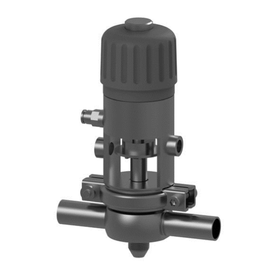
Description Design of the valve Description Design of the valve Fig.4: Main components on the valve Designation Seal ring Bearing Lantern Valve disk Handwheel Switching disk Clamp Housing 430BAL008583EN_1 12.08.2019... -
Page 16: Transport And Storage
Transport and storage Scope of supply Transport and storage Scope of supply On receipt of the valve check whether • the details on the main valve components correspond to the data in the order and delivery documents, • the equipment is complete and all components are in good order. Transport For transport, the following principles apply: •... -
Page 17: Technical Data
Technical data Type plate Technical data Type plate The type plate clearly identifies the valve. Fig.5: Type plate The type plate provides the following key data: Key data of the valve Type Control valve type I Serial Serial number Material 1.4404 (AISI316L) / EPDM (FDA) Control air pressure bar/psi max. -
Page 18: Resistance Of The Sealing Materials
Technical data Resistance of the sealing materials Technical data: Compressed air supply Designation Description 5 bar (72.5 psi) standard Product pressure max. 10 bar (116 psi) Control air pressure 6 bar, max. 8 bar Control air acc. to ISO 8573-1 Quality class 6 Particle size max. -
Page 19: Pipe Ends - General Table Of Measurements
Technical data Pipe ends - General table of measurements Seal resistance for EPDM, FKM, HNBR, PTFE Medium Temperature Sealing material (general operating temperature*) EPDM HNBR PTFE -40...+135 °C * -10...+200 °C * -25...+140 °C * -200...+260 °C (-40...275 °F) (+14...+392 °F) (-13...+284 °F) (-328...+500°F) Inorganic acids up... -
Page 20: Lubricants
Technical data Lubricants Dimensions for tubes in Inch OD Outside Outside Wall Inside Inch OD diameter acc. diameter thickness diameter to BS 4825 1" 25.4 1.65 22.1 1.5" 38.1 1.65 34.8 2" 50.8 1.65 47.5 2.5" 63.5 1.65 60.2 3" 76.2 1.65 72.9... -
Page 21: Assembly And Installation
Assembly and installation Safety instructions Assembly and installation Safety instructions Hazardous situations during installation can be avoided by safety-conscious and proactive behaviour of the personnel. For installation, the following principles apply: • Only qualified personnel are allowed to set-up, install and commission the component. -
Page 22: Valve With Welded Ends
Assembly and installation Valve with Welded Ends Valve with Welded Ends This section describes the welding procedure for the valve housing. Warning! Spring tension in the valve Danger of injury when opening the clamp connections on the actuator or on the housing as the released spring pretension will suddenly lift the actuator. -
Page 23: Start-Up
Start-up Safety instructions Start-up Safety instructions Initial commissioning For initial commissioning, the following principles apply: • Take protective measures against dangerous contact voltages in accordance with pertinent regulations. • The valve must be completely assembled and correctly adjusted. All screw connections must be securely tightened. -
Page 24: Operation And Control
Operation and control Safety instructions Operation and control Safety instructions Dangerous situations during operation can be avoided by safety-conscious and proactive behaviour of the personnel. For operation, the following principles apply: • Monitor the component during operation. • Safety devices must not be changed, removed or taken out of service. Check all safety devices at regular intervals. -
Page 25: Cleaning And Passivation
Cleaning and Passivation Cleaning Cleaning and Passivation Cleaning All parts in contact with product must be cleaned at regular intervals. Always observe the safety data sheets issued by the cleaning agent manufacturers. Only use cleaning agents which do not cause damage to the seals and the inner parts of the valve. -
Page 26: Passivation
Cleaning and Passivation Passivation We recommend a flow velocity of at least 2 m/s. Passivation Before commissioning a plant, passivation is commonly carried out for long pipes and tanks. Valve blocks are usually excepted from this. Passivation is typically performed using nitric acid (HNO ) at approx. -
Page 27: Maintenance
Maintenance Safety instructions Maintenance 10.1 Safety instructions Maintenance and repair Before carrying out maintenance and repair work on the component's electrical equipment, perform the following steps in accordance with the "5 safety rules": • Isolate from the power supply • Take appropriate measures to prevent switch on •... -
Page 28: Inspections
Maintenance Inspections • Disconnect all power and utility lines. • Markings, e.g. on lines, must not be removed. • Do not climb on the component. Use suitable access aids and working platforms. • Mark the lines (if unmarked) prior to disassembly to ensure they are not confused when re-assembling. -
Page 29: Prior To Removal
Maintenance Prior to removal Guideline Values for Maintenance Intervals Maintenance intervals Applications (guideline values) Media at temperatures of 60 °C to 130 °C approx. every 3 months (140 °F to 266 °F) Media at temperatures of < 60 °C approx. every 12 months (<... -
Page 30: Removing The Valve Disk
Maintenance Disassembling the Valve 10.5.1 Removing the valve disk Graphic POS. 31 AND 9 are missing! Please add in new graphic revision | ZINDEL AG 4.4.19 Fig.6: Removing the Valve Disk Carry out the following steps: Turn the handwheel (20) counterclockwise. –... -
Page 31: Maintenance
Maintenance Maintenance Turn the handwheel (20), together with piston rod (16), piston (17) and spring, out of the lantern. Tension the spring using the mounting tool, material no. 222-601.51. Pull off the circlip (27). Use the mounting tool (A), material no. 222-601.51, to relieve the tension on the spring and remove the mounting tool. -
Page 32: Installing The Valve
PARALIQ GTE 703 can be ordered from GEA Tuchenhagen under mat. no. 413-064, and Rivolta F.L.G. MD-2 can be ordered under mat. no. 413-071. Using other types of grease can result in malfunctions or in premature seal failure. -
Page 33: Alarms
Alarms Malfunctions and remedies Alarms 11.1 Malfunctions and remedies In the event of malfunctions immediately deactivate the valve and secure it against inadvertent reactivation. Malfunctions may only be remedied by qualified staff, who must observe the safety precautions. Malfunction Cause Remedy Dirt/foreign material between Clean valve housing and valve... -
Page 34: Decommissioning
Decommissioning Safety precautions Decommissioning 12.1 Safety precautions For shutting down, the following principles apply: • Switch off the compressed air. • Switch off the component with the main switch. • Padlock the main switch (if fitted) in the off position to prevent it from being switched back on. -
Page 35: Parts List - Sampling Valve I
Parts list - sampling valve I Parts list - sampling valve I Fig.9 Fig.10: A = accessories / B = alternative outlets for item 32 430BAL008583EN_1 12.08.2019... - Page 36 Parts list - sampling valve I Item Designation Material DN 10 DN 15 DN 25 DN 40 DN 50 Set of seals complete 1) EPDM 221-004744 221-004744 221-004747 221-004750 221-004750 221-004745 221-004745 221-004748 221-004751 221-004751 HNBR 221-004746 221-004746 221-004749 221-004752 221-004752 Seal ring EPDM...
- Page 37 Parts list - sampling valve I Item Designation Material DN 10 DN 15 DN 25 DN 40 DN 50 Spiral flame nozzle 1.4404 229-146.07 229-146.07 229-146.07 229-146.07 229-146.07 Outlet type I-SCHÜTT 1.4404 221-268.09 221-268.10 221-268.10 Outlet type I-LUER 1.4404 221-268.11 221-268.12 221-268.12 Outlet type I-KEOFIT...
- Page 38 Parts list - sampling valve I Item Designation Material DN 65 DN 80 DN 100 DN 125 DN 150 Set of seals complete 1) EPDM 221-004750 221-004750 221-004750 221-004750 221-004750 221-004751 221-004751 221-004751 221-004751 221-004751 HNBR 221-004752 221-004752 221-004752 221-004752 221-004752 EPDM 924-255...
- Page 39 Parts list - sampling valve I Item Designation Material DN 65 DN 80 DN 100 DN 125 DN 150 Outlet type I-SCHÜTT 1.4404 221-268.10 221-268.10 221-268.10 221-268.10 221-268.10 Outlet type I-LUER 1.4404 221-268.12 221-268.12 221-268.12 221-268.12 221-268.12 Outlet type I-KEOFIT 1.4404 221-268.14 221-268.14...
- Page 40 Parts list - sampling valve I Item Designation Material 1"OD 1.5"OD 2" OD 2.5"OD 3" OD Set of seals complete 1) EPDM 221-004747 221-004750 221-004750 221-004750 221-004750 221-004748 221-004751 221-004751 221-004751 221-004751 HNBR 221-004749 221-004752 221-004752 221-004752 221-004752 Seal ring EPDM 924-255 924-255...
- Page 41 Parts list - sampling valve I Item Designation Material 1"OD 1.5"OD 2" OD 2.5"OD 3" OD Outlet type I-LUER 1.4404 221-268.11 221-268.12 221-268.12 221-268.12 221-268.12 Outlet type I-KEOFIT 1.4404 221-268.13 221-268.14 221-268.14 221-268.14 221-268.14 Outlet type I-LUER/90° 1.4404 221-268.15 221-268.16 221-268.16 221-268.16 221-268.16...
- Page 42 Parts list - sampling valve I Item Designation Material 4" OD 6" OD 2" IPS 3" IPS 4" IPS 6" IPS Set of seals complete 1) EPDM 221-004750 221-004750 221-004750 221-004750 221-004750 221-004750 221-004751 221-004751 221-004751 221-004751 221-004751 221-004751 HNBR 221-004752 221-004752 221-004752...
- Page 43 Parts list - sampling valve I Item Designation Material 4" OD 6" OD 2" IPS 3" IPS 4" IPS 6" IPS Flammable outlet 1.4404 229-146.08 229-146.08 229-146.08 229-146.08 229-146.08 229-146.08 90° Spiral flame 1.4404 229-146.07 229-146.07 229-146.07 229-146.07 229-146.07 229-146.07 nozzle Outlet 1.4404...
- Page 44 Parts list - sampling valve I Seals for sampling valve I Item Designation Material DN 10/15 DN 25 DN 40-150 1" 1.5" - 6" Seal ring Ø EPDM 924-255 924-255 924-255 924-297 924-297 924-297 HNBR 924-312 924-312 924-312 O-ring Ø 42 x 3 60 x 3 EPDM...
-
Page 45: Appendix
Appendix Lists Appendix 14.1 Lists 14.2 Abbreviations and terms Abbreviation Explanation British Standard Unit of measurement of pressure [bar] All pressure data expressed in [bar/psi] is assumed to be gauge pressure [barg/psig] unless explicitly specified otherwise. approx. approximately °C Unit of measurement of temperature [degree Celsius] valve coefficient, non-metric flow coefficient, see K Unit of measurement of volume [cubic decimetre] standard volume (standard litres) - Page 46 Appendix Abbreviation Explanation µm Unit of measurement of length [micrometre] Metric Unit of measurement of work [newton metre] TORQUE SPECIFICATION: 1 Nm = 0.737 lb-ft Pound-Force (lb)× Feet (ft) Polyamide PE-LD Low-density polyethylene Polytetrafluoroethylene Anglo-American unit of measurement for pressure [pound- force per square inch] All pressure data expressed in [bar/psi] is assumed to be gauge pressure [barg/psig] unless explicitly specified...
- Page 47 Appendix 430BAL008583EN_1 12.08.2019...
Need help?
Do you have a question about the VARIVENT Series and is the answer not in the manual?
Questions and answers