
Related Manuals for Matelec HydroTOUCH Multipump


Summary of Contents for Matelec HydroTOUCH Multipump
- Page 1 C O N T R O L P U M P OW NER’S OPERATION & COMMISIONIN G MANUAL Mate l ec Hy droTOU CH Multi pum p Contr oller Specifi ca ti ons DOC: Hydro Touch DOL_Soft Starter VER 2.1...
-
Page 2: Table Of Contents
CONT ENTS Introduction Overall Solution Commissioning Connections Login Easy Setup Wizard Motor Data Operation Main screen Pump screen Overview screen Alarms screen Logged Data screen Diagnostic screen 12-13 Wizard Menu Structure Functions Application Selection Pump 1 mode Pump Limiting Pump Anti-seize Mains Water bypass Mains Tank top up UV Lamp Control... -
Page 3: Introduction
Introducti on Your HydroTOUCH is a second generation, multi-pump controller designed to operate up to 12 pumps. It both digital and analogue. With the use of an easy setup wizard and ‘user friendly’ touch screen design the operation of your system should be a delight. This manual provides all necessary operating information for the controller and touch screen. -
Page 4: Overall Solution
Overall So lu tio n Electrically the system is composed of three main components: the controller, pump starters and Human Machine Interface (HMI). The following diagram depicts the basic layout: INPUT CONTROLLER DEVICES PUMP PUMP PUMP PUMP STARTER STARTER STARTER STARTER The HydroTOUCH has been designed to be a flexible solution for all aspects of feedback controlled pumps. -
Page 5: Commissioning
Comm issio n in g CONNECTIONS Standard Connections A1 A2 High Flow System Primary Secondary Level Level Input Fault Transducer Transducer FLoat PUMP 1 PUMP 2 SUPPLY Thermal Switch INPUT 415Vac 24Vdc 24Vdc PUMP 1 PUMP 2 4-20mA Volt/F BRIDGE IF NOT REQUIRED (Number of Pumps will depends... -
Page 6: Login
LOGIN After the power, probes and pumps have been connected the HydroTOUCH is ready for commissioning. On initial power up, the HydroTOUCH will request the setup wizard be run to configure the system to suit site requirements. Once the wizard has been fully completed and saved the configuration will be stored into memory. -
Page 7: Easy Setup Wizard
EASY SETUP WIZARD During the easy setup wizard you will be prompted to enter all the relevant information to configure the system. Some of the important features that must be set correctly in the wizard are listed below. - Pump 1 Mode The first pump can be configured as a main pump, jacking pump or a mixer. - Page 8 Trip Curves As for thermal relay time-current characteristic curve, please see below graph: The current sensing circuits can measure a maximum of 11x the full load current and thus the minimum trip time is limited to approximately 2.5 seconds as shown in the above plot. In the case of a lower overload setting (for example, 10A) the system can react proportionally to even higher multiples of the full load current.
-
Page 9: Operation
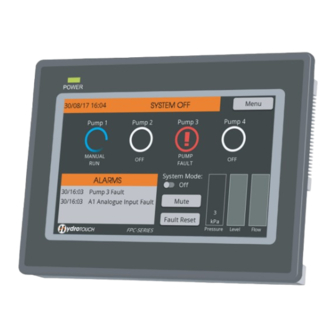
Opera tio n MAIN SCREEN The main screen shows how the system is operating and the status of faults, pumps and sensors. All elements can be touched to gain further information from this screen. The menu in the top right corner gives access to further screens for parameter adjustment, to view logged data or past faults or to rerun the wizard if site conditions have changed. -
Page 10: Overview Screen
OVERVIEW SCREEN The overview screen is a handy tool to monitor the entire system operation. For ease of use, it will be automatically configured depending on what is set during the easy setup wizard. ALARM SCREEN Pressing on the current alarms table will bring up the full alarms screen. This screens keeps a log of all past faults with an accurate time and date stamp. -
Page 11: Logged Data Screen
LOGGED DATA SCREEN The logged data screen can be accessed through the main menu. On this page you will find access to trend graphs for power, pressure, flow and tank level. Usage graphs for total monthly power and water usage. Run timers for each pump and counters for system event information. -
Page 12: Wizard Menu Structure
WIZARD MENU STRUCTURE S T A R T P R E S S U R E C O N T R O L L E V E L C O N T R O L T E M P. C O N T R O L... - Page 13 E N D...
-
Page 14: Functions
Fu nc ti on s APPLICATION SELECTION The HydroTOUCH has been designed for three different control operations Pressure, Level and Temperature. The basic function of the three operations are laid out below. 1. ‘Constant Pressure’ is based around a 4-20mA pipe mounted pressure transducer as the feedback source. -
Page 15: Pump Anti-Seize
PUMP ANTI-SEIZE For systems that have extensive pump idle times the anti-seize feature will run the pump for 6 seconds every 7 days if the pump has not run. Every pump has an individual pump idle timer to ensure each pump is prevented from seizing and not started if it has run within the 7 day period. -
Page 16: Transducer Redundancy
TRANSDUCER REDUNDANCY If the system is supplying a critical application a backup transducer can be assigned for the feedback signal to ensure if a failure or error occurred with the feedback signal the system will seamlessly changeover and continue normal operation. To enable this feature through the wizard select the ‘backup’ option for the secondary analogue input assign. -
Page 17: Hydrotouch Connections
5.14 HYDROTOUCH CONNECTIONS Assignable Outputs 4-20mA DIGITAL VOLT FREE 24Vdc Power Supply Analogue 1 Analogue 2 TOUCH M U L T I P U M P V S D C O N T R O L L E R Auxillary Touch Remote Drives... -
Page 18: System Faults
SYSTEM FAULTS Fault Cause Remedy System Pressure has gone below the -Check ‘Low pressure threshold’ parameter is Pressure acceptable level set correctly Fault - Burst pipe -Investigate cause of low pressure event - Pump loss of prime -Incorrect parameter settings High Tank level analogue input has gone above - Inspect the level in the tank/pit... -
Page 19: Wizard Parameter List
Wi z ard P ara meters Li st PAGE PARAMETERS MATELEC DEFAULT USER SETTING Pump 1 Mode Main Pump Jacking 1 Pump Turn off enable Disabled Jacking Pump Turn off delay 10 Seconds Pumps Mixer Pump Start Delay 30 Seconds... -
Page 20: User Setting
PAGE PARAMETERS MATELEC DEFAULT USER SETTING Proportional Level Mains Tank Fill Enable Disabled Constant Top Up Start Level 1.0m Level Setup Top Up Stop Level 2.0m Constant Temperature Temperature Units Celcius Temperature Transducer Range 100.0 Constant Setpoint 50.0 Temp. Duty Start Step...
Need help?
Do you have a question about the HydroTOUCH Multipump and is the answer not in the manual?
Questions and answers