Advertisement
QUICK START GUIDE
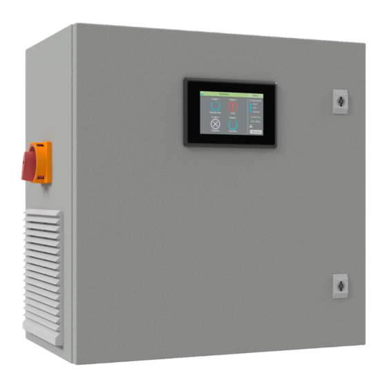
HydroWHIZ Pump Controllers
VSD
Single Phase - FPC-63X21 (1-6 Pumps)
Three Phase - FPC-63X20 (1-6 Pumps)
Introduction
The HydroWHIZ Controller has been designed with ease of use at the core of the system design. Building on the wealth of the pump
control features in the Advanced controller, the HydroWHIZ brings these features into a new age with a color touch screen interface
and a streamlined setup process. In a world where information is power the HydroWHIZ has extensive time and date stamped
alarms, logged data, trend graphs and diagnostic pages to provide the user with all the information required for optimisation and
preventative maintenance. Featuring the flexibility of level, pressure and temperature system modes with a wide range of functions
and protections, the HydroWHIZ VSD controller is ideal for a wide range of applications including water transfer, stormwater and
sewage pump out, constant pressure, hot water circulation and chiller supply, to name a few.
For more information on the operation of the HydroWHIZ VSD controller see the HydroWHIZ VSD Operation Manual.
Safety
This control panel has been designed and built for applications that are Commercial and/or Industrial in nature, operation, function
and location. If the control panel is to be used in Domestic/Residential applications, where specific Wiring Rules in respect of 'electrical
supply' protection may apply, it is the responsibility of the installing electrician to ensure compliance with relevant standards.
•
Prior to installation, ensure power supply is isolated.
•
Power supply must be circuit breaker protected (qualified electrician to determine appropriate amp rating).
•
It is highly recommended that RCDs are NOT used to protect the supply to this panel. The VSDs in this panel have EMC filtering
which can cause nuisance tripping of RCDs. It is recommended to use alternative protection for the incoming cables. If RCDs
are required, type B RCDs must be used, taking into consideration the VSD earth leakage current to avoid nuisance tripping.
•
Electrical connection to the panel must be carried out in accordance with the following pages.
•
Additions or modifications to the control panel are not permitted and will void warranty.
•
The controller is not intended for use by children or infirm persons without supervision.
•
Repairs to the controller must only be carried out by a suitably qualified electrician.
This manual makes use of the following symbols to indicate warnings that must be paid specific attention to:
Damage to equipment or personal harm may occur if this instruction is not followed
Electrical risk (electrocution hazard) may occur if this instruction is not followed
1
P: 1800 281 282
|
F: 1300 281 282
|
E: info@matelecaustralia.com.au
|
W: www.matelecaustralia.com.au
V1.7
Advertisement
Table of Contents

Related Manuals for Matelec Hydrowhiz FPC-63X21


Summary of Contents for Matelec Hydrowhiz FPC-63X21
- Page 1 QUICK START GUIDE HydroWHIZ Pump Controllers Single Phase - FPC-63X21 (1-6 Pumps) Three Phase - FPC-63X20 (1-6 Pumps) Introduction The HydroWHIZ Controller has been designed with ease of use at the core of the system design. Building on the wealth of the pump control features in the Advanced controller, the HydroWHIZ brings these features into a new age with a color touch screen interface and a streamlined setup process.
-
Page 2: Step 1 - Installation
Harmonic Consideration With all variable speed drives there will be some harmonic distortion on the main power supply. The drives used in the HydroWHIZ VSD have internal filters to reduce the amount of distortion, however in some applications additional filtering may be required. If additional harmonic filtering is required to meet site specifications this can be requested. - Page 3 Control output type Changing this parameter could result in unexpected behaviour. Number of pumps Switch system to off? Current Date: 2020 Pump limit Duty change period 60 Mins Cancel Save MATelec Australia reserves the right to alter technical data without notice...
-
Page 4: System Setup
Step 5 - Setup (Continued) The Setup Screen is where the controller is configured for operation. The pages following the System Setup page will change depending on whether the ‘Level’, ‘Pressure’ or ‘Temperature’ system type is selected, allowing users to adjust settings that are specific to that application. All user adjusted settings can be recorded on the last page of this guide. - Page 5 When the analog goes below this threshold for 3 seconds the Low temperature protection will be threshold activated. High temperature When the analog goes above this threshold for 3 seconds the High temperature protection will be threshold activated. MATelec Australia reserves the right to alter technical data without notice...
- Page 6 Step 5 - Setup (Continued) 5.9 - 3 Function The functional setup for the system. RUNNING MENU RUNNING MENU RUNNING MENU Setup: 3 Function Setup: 3 Function Setup: 3 Function Level Control Lower/empty/cool Jacking pump Temperature control Lower/empty/cool Low level protection Lockout Low pressure protection Lockout...
- Page 7 This is the speed a VSD controlled pump will run in manual. If the system is in auto and a duty or standby pump is running then the auto speed will override the manual speed. MATelec Australia reserves the right to alter technical data without notice...
- Page 8 Step 5 - Setup (Continued) 5.11 - Additional information for setting the PID The PID algorithm is used to control the speed of the pumps in the pressure VSD configuration to maintain a stable setpoint. Generally larger pumps will need to have a slower PID response to smaller pumps. Care must be taken adjusting these values as they can cause the system to become unstable.
- Page 9 SCADA watchdog alarm will be activated and the pumps shutdown. This is used as a ‘Keep alive’ function. SCADA watchdog The delay after the last successful modbus command before the SCADA watchdog alarm would be period activated. MATelec Australia reserves the right to alter technical data without notice...
-
Page 10: Return To Menu
Step 5 - Setup (Continued) 5.15 - Return to Menu Once all the Setup screens have been completed, tap to return to the Menu screen. RUNNING MENU Setup: 6 SCADA Setup SCADA baud rate 19,200 SCADA parity 8 None 1 SCADA slave address SCADA watchdog enable SCADA watchdog timeout... - Page 11 Once Step 6.1A is completed for the first VSD, remove the screen and connect to the other VSDs in the panel and commission them. Then skip Step 6B and complete Step 7 to finish setting up the controller. MATelec Australia reserves the right to alter technical data without notice...
- Page 12 Step 6B - VSD Commissioning (ABB Drives) See Step 6A for Lenze drive commissioning. To commission VSDs access to live parts is required. This step should only be completed by someone suitably qualified to do so. VSD Control Panel Overview The following table summarises the key functions and displays on the basic control panel.
-
Page 13: User Settings
Standby start temp step pressure step Low temperature Low level threshold Low pressure threshold threshold High temperature High level threshold High pressure threshold threshold Additional user settings on following page MATelec Australia reserves the right to alter technical data without notice... - Page 14 Max run fault protection Max run fault delay Pump cycle protection No flow protection 6 - SCADA SCADA baud rate SCADA parity SCADA slave address SCADA watchdog enable SCADA watchdog period MATelec Australia reserves the right to alter technical data without notice...
Need help?
Do you have a question about the Hydrowhiz FPC-63X21 and is the answer not in the manual?
Questions and answers