Table of Contents
Advertisement
Advertisement
Table of Contents

Subscribe to Our Youtube Channel
Related Manuals for Matelec FPC-36040


Summary of Contents for Matelec FPC-36040
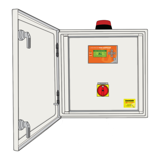
- Page 1 I n sta lla t io n and Op e ra ting Instru ction s MOD EL: FP C-36040 DUAL PUMP CONTROL PUMP 1 PUMP 2 AUTO AUTO Running Idle System OK. No Alarms MAIN ISOLATOR DOC: FPC-36040 VER 1.0...
- Page 2 Your Advance Dual Pump Controller reflects the superior quality and attention to detail in design, engineering and manufacturing that has distinguished MATelec. Products for decades. The controller incorporates the very latest in micro-processor technology, ensuring you, the owner/operator, of many years of functional, reliable and ‘user friendly’...
-
Page 3: Installation
I NSTALLATION MOUNTING FRONT SIDE VIEW 1. Controller enclosure must be mounted in a vertical position. 2. Ensure mounting method does not compromise enclosure weather proof rating. DUAL PUMP CONTROL PUMP 1 PUMP 2 AUTO AUTO Running Idle System OK. No Alarms 3. -
Page 4: Operation
OPERA TIO N This controller can perform control functions for most Dual Pump pumping applications. It is more than likely that the control parameters have already been set up for your particular application, however, hereunder you will find details of the setup and configuration options. There are 6 DIP switches located on the lower side of the control module, which allows for selecting “mode”... - Page 5 The basic logic on which a High or Low Level Alarm is determined, is set out in the Table below: Input 1 Input 2 Input 3 Input 4 Pump Alarm State Low Level Pump Stop Pump Start High Level Closed Open/Closed Open Open...
- Page 6 In pressure pump mode some of the optional features are disabled, including maximum run alternation, anti-seize and maximum idle timers Mode ‘Current Loop’: Level Transducer (4-20mA) Configuration In order to activate current loop mode the enclosure must be opened and jumper J10 moved to the “current loop enabled”...
- Page 7 The HMI When power is applied the HMI immediately starts up, displaying a “splash screen” with the Matelec logo and software revision is displayed for several seconds. Once the splash screen disappears the HMI will then display the main screen which gives an overview of the system.
-
Page 8: Input States
ALARMS ALARMS Alarm: High level No alarms Alarm: Pump 1 fault Press OK for alarm test Press ‘OK’ to reset alarms Alarms screen with no alarms Alarm screen with multiple alarms If any alarms are active the alarm screen will appear as shown on the right image above and list up to 5 of the active alarms. -
Page 9: Edit Parameters
1.6 Parameters The Function Parameters screen operates identically to the Logged Data screen, but instead presents all of the operation parameters for the controller. Refer to the APC6 specifications for details regarding each of the parameters. The up and down buttons are used to scroll through the list. PARAMETERS Pump stop - Level 0.3m... -
Page 10: System Information
1.9 4-20mA Display Modes When the APC6 current loop mode is enabled the HMI is able to report the current 4-20mA reading (this is shown on the inputs menu screen). In addition, it can convert this reading into one of two types of scale: metres or kPa. The metres scale can be adjusted for a maximum range of 0.1 to 25.0 metres (in 0.1m increments) and the kPa scale can be adjusted for a maximum range of 10 to 2500kPa in 10kPa increments. -
Page 11: Modbus Communications
MODBUS COMMUNICATIONS Modbus is a serial communications protocol originally designed for use PLCs. Simple and robust, it has since become one of the de facto standard communications protocols in the industry, and it is now amongst the most commonly available means of connecting industrial electronic and control devices. 2.1 Modbus Settings In order to reduce unnecessary complexity, the system is compatible with with the BASIC Modbus implementation class with some additional features, as detailed in the following table. -
Page 12: Modbus Registers
2.5 Address Reference The following tables list all valid Modbus coil and register addresses for the Controller and the data contained within: MODBUS REGISTERS Block Modbus Address Register Data Read/Write Function Codes Description I/O States 0=Off,1=On Alarm States 0=Off,1=On System States 0=Off,1=On Mute Alarm 0=Off,1=On... -
Page 13: Modbus Coils
MODBUS COILS Modbus Func- Modbus HEX Coil Read/ Block Coil Register Data Coil Data tion Description Address Address Write Address Codes 0x00 Low level in 0x01 Stop in 0x02 Start in 0x03 High level in 0x04 I/O States Pump 1 fault in 0=Off;1=On 0x05 Pump 2 fault in... -
Page 14: Circuit Diagram
CIRCUIT DIAGRAM FPC-36040 c/w Floats 415 Vac Supply L2 L3 MSW1 Main Isolator TOL1 415VAC Pump Contactor 3P Thermal Overload Isolator 3P 32A TOL2 415VAC Pump Contactor 3P Thermal Overload Isolator 3P 32A Circuit Breaker 2A 240V 240N 12Vac 0Vac... - Page 15 FPC-36040 c/w Transducer 415 Vac Supply L2 L3 MSW1 Main Isolator TOL1 415VAC Pump Contactor 3P Thermal Overload Isolator 3P 32A TOL2 415VAC Pump Contactor 3P Thermal Overload Isolator 3P 32A Circuit Breaker 2A 240V 240N 12Vac 0Vac Transformer 12Vac...
- Page 16 - Mutes active audible alarm. MUTE DISTRIBUTED BY: INSTALLATION DATE: SERIAL NUMBER: MANUFACTURED BY MATelec AUSTRALIA MANUFACTURED BY MATelec AUSTRALIA EMAIL: info@matelecaustralia.com.au EMAIL: info@matelecaustralia.com.au MATelec reserves the right to alter technical specifications without notice MATelec reserves the right to alter technical specifications without notice...
Need help?
Do you have a question about the FPC-36040 and is the answer not in the manual?
Questions and answers