
Subscribe to Our Youtube Channel
Related Manuals for Matelec FPC-30040-CON


Summary of Contents for Matelec FPC-30040-CON
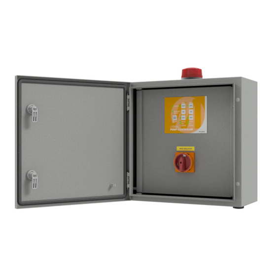
- Page 1 OP ER ATION MANUAL Dua l Pu m p Co ntro ll e r Inst all ation an d O perating Instructio ns MOD EL: FP C-30040-C ON PUMP ON PUMP ON FAULT FAULT MAIN ISOLATOR DOC: FPC-30040-CON VER 1.0...
- Page 2 Your Dual Pump Controller reflects the superior quality and attention to detail in design, engineering and manufacturing that has distinguished MATelec Products for decades. The controller incorporates the very latest in micro-processor technology, ensuring you, the owner/operator, of many years of functional, reliable and ‘user friendly’...
- Page 3 Bottom Bottom not compromise the weather proof rating of the enclosure. WIRING CONNECTION DETAIL FPC-30040-CON C O NNECT IO N T1 T2 T1 T2 E5 E1 E2 E3 Common A1 A2 Fault...
- Page 4 OPERA TIO N This controller can perform control functions for most Dual Pump pumping applications. It is more than likely that the control parameters have already been set up for your particular application, however, hereunder you will find details of the setup and configuration options. There are 6 DIP switches located on the lower side of the control module, which allows for selecting “mode”...
- Page 5 The basic logic on which a High or Low Level Alarm is determined, is set out in the Table below: Input 1 Input 2 Input 3 Input 4 Pump Alarm State Low Level Pump Stop Pump Start High Level Closed Open/Closed Open Open...
- Page 6 In pressure pump mode some of the optional features are disabled, including maximum run alternation, anti-seize and maximum idle timers In order to activate current loop mode the enclosure must be opened and jumper J10 moved to the “current loop enabled”...
- Page 7 Sensitivity adjustable by a potentiometer (5-100kΩ) Measuring frequency 10Hz prevents polarization of liquid and raising oxidation of measuring probes Galvanically separated supply voltage UNI 24.. 240 VAC/DC HRH-5 DATA SHEET Output contact 1xchangeover/SPDT 8A/250V AC1 1-MODULE, mounting onto a DIN rail Device description Supply voltage terminals Terminals for conection of...
- Page 8 Galvanically separated supp Output contact 1xchangeove EAN code 1-MODULE, mounting onto a 8595188136396 HRH-5 /UNI Device description HRH-5 Technical parameters Functions: Supply terminals: A1 - A2 Voltage range: 24... 240 V AC/ DC (AC 50 - 60 Hz) Indication of supply voltage Input: max.
- Page 9 Output contacts i / Silver Alloy ) Connection Monitoring of two levels Monioring of one level V DC to 131 °F) F to 158 °F) ensors) Tank with Tank with monitored level monitored level 10 terminals Function Function PUMP UP Function PUMP DOWN x 0.7˝...
- Page 10 CIRCUIT DIAGRAM 415 Vac Supply MSW1 Main Isolator TOL1 415VAC Pump Contactor 3P Thermal Overload Circuit Breaker TOL2 415VAC Pump Contactor 3P Thermal Overload Circuit Breaker Circuit Breaker 2A 240V 240N 12 Vac 0Vac Transformer 12Vac Contactor 18A 240Vac TOL2 Thermal NC Contact Pump 2...
- Page 11 NOTE S...
- Page 12 Manual Pumping Mode FLASHING A prime loss fault has occurred. DISTRIBUTED BY: INSTALLATION DATE: SERIAL NUMBER: MANUFACTURED BY MATelec AUSTRALIA EMAIL: info@matelecaustralia.com.au MATelec reserves the right to alter technical specifications without notice.
Need help?
Do you have a question about the FPC-30040-CON and is the answer not in the manual?
Questions and answers