Fuji Electric MICREX-SX SPH Series User Manual
Hide thumbs
Also See for MICREX-SX SPH Series:
- User manual (135 pages) ,
- User manual (47 pages) ,
- User manual (94 pages)

Subscribe to Our Youtube Channel
Related Manuals for Fuji Electric MICREX-SX SPH Series


Summary of Contents for Fuji Electric MICREX-SX SPH Series
- Page 1 series USER’S MANUAL T-link Master Module (Type: NP1L-TL1) T-link Interface Module (Type: NP1L-RT1) T-link Slave Module (Type: NP1L-TS1) FEH204c...
- Page 2 *This manual is structured to be applicable to both D300win and Standard Loader. *In addition to the above manuals, the following Fuji Electric FA Components & Systems Co., Ltd. site offers various manuals and technical documents associated with MICREX-SX.
-
Page 3: Safety Precautions
Safety Precautions When using this product, observe the safety precautions. In this manual, precautions are classified into two levels according to their severities: Warning Failure to observe warnings may result in deaths or serious injuries. Caution Failure to observe cautions may result in slight or medium injuries or physical damages. Note that precautions marked as may also result in serial conditions, unless observed, according to the Caution... - Page 4 Safety Precautions Caution ◊ Do not use the product or parts found damaged or deformed when unpacking. If done, fire, malfunctions, or failures may occur. ◊ Do not give shock to the product by dropping or turning it over. If done, the product may be damaged or failures may occur.
- Page 5 Revisions • c i f n i l • n i l • • • • n i l n i l • • " " 8 • t c i t t i • " t c i . " •...
-
Page 6: Table Of Contents
Contents Preface Safety Precautions Revisions Contents Page Section 1 General ....................1-1 1-1 T-link System Configuration ........................1-1 1-2 Communication System Using the T-link Slave Module ..............1-2 1-3 Overview of the T-link Expansion Function ..................1-3 1-4 Overview of the I/O Expansion Function ..................... 1-4 1-5 Supported version .......................... - Page 7 Contents Page Section 5 Wiring....................5-1 5-1 Precautions .............................5-1 5-2 T-link Wire Assembling ...........................5-2 Section 6 Troubleshooting ................. 6-1 6-1 LED Indication in Various System Conditions ..................6-1 6-2 System Memory ............................6-2 6-3 Diagnosing the Status by Loader ......................6-5 6-3-1 System RAS information ..........................6-8 6-3-2 SX bus transmission information ........................
-
Page 8: Section 1 General
Section 1 General Page 1-1 T-link System Configuration ..................1-1 1-2 Communication System Using the T-link Slave Module ........1-2 1-3 Overview of the T-link Expansion Function ............1-3 1-4 Overview of the I/O Expansion Function ............... 1-4 1-5 Supported version ....................1-5 (1) T-link expansion supported version ..................... -
Page 9: T-Link System Configuration
T-link master module “NP1L-TL1” is the communication module that has the master function and enables us to construct one T- link system, or Fuji Electric’s original device level network, with one unit of it. NP1L-RT1 is the T-link interface module that is used to construct a T-link I/O group-type unit. -
Page 10: Communication System Using The T-Link Slave Module
1-2 Communication System Using the T-link Slave Module By connecting a T-link slave module to the SX bus, you can communicate with other PLC system having the T-link master function via T-link. Communication using the T-link slave module is suitable for simply communicating a comparatively small volume of data with existing PLC system having the T-link master function. -
Page 11: Overview Of The T-Link Expansion Function
1-3 Overview of the T-link Expansion Function The T-link expansion function expands the total number of I/O words for the T-link devices that can be connected to one unit of T-link master module from maximum 128 words (2048 points) to maximum 512 words (8192 points). <Outline of T-link expansion>... -
Page 12: Overview Of The I/O Expansion Function
1-4 Overview of the I/O Expansion Function The I/O expansion function include functionality of “T-link expansion”. In addition, it expands total number of I/O words for one CPU from 512 words (8192 points) to 4096 words (65536 points). Please note total number of I/O words for one T-link master is 512 words. -
Page 13: Supported Version
1-5 Supported version (1) T-link expansion supported version n i l c t i (2) I/O expansion supported version n i l c t i Note: NP1PS-32/32R, board type PLC are not supported. (3) 64 stations for one T-link master supported version n i l Note: As for system configuration, please see clause 3-2-6. -
Page 14: Slave Module Mounting On Np1L-Rt1 Base Supported Version
1-5 Supported version (4) Slave module mounting on NP1L-RT1 base supported version n i l n i l (5) High-speed counter module mounting on NP1L-RT1 base supported version n i l n i l Note: The only mountable high-speed counters are the 2ch products (models: NP1F-HC2 / HC2MR / HC2MR1). -
Page 15: Section 2 Specifications
Section 2 Specifications Page 2-1 General Specifications .................... 2-1 2-2 T-link Communication Specifications ..............2-2 2-2-1 Communication specifications ................... 2-2 2-2-2 Basics of T-link transmission ....................2-2 (1) Initial transmission ..........................2-2 (2) Normal transmission ........................... 2-2 (3) Transmission errors ..........................2-2 2-2-3 Transmission types ...................... -
Page 16: General Specifications
General Specifications Section 2 Specifications 2-1 General Specifications ° C ° C v i t y t i l l o y t i i t l i l p y l l y l l µ y t i ±... -
Page 17: T-Link Communication Specifications
Communication Specifications 2-2 T-link Communication Specifications 2-2-1 Communication specifications n i l n i l n i l n i l i t l c i t c i t c i l n i l ) r i n i l c i t n i l c i t... -
Page 18: Transmission Types
Communication Specifications 2-2 T-link Communication Specifications 2-2-3 Transmission types The T-link handles I/O transmission and message transmission. (1) I/O transmission I/O transmission is a high-speed communication method enabling transmission of signals from distributed I/O devices to the PC. On the T-link data refresh is usually performed every 10ms. However, if one T-link system is connected to a large number of I/O devices or there are a large number of occupied words, the refresh cycle may exceed 10ms. -
Page 19: Cable
Cable 2-3 Cable Cables that meet the following specifications should be used for the T-link cables. Note: The maximum length values in the above table are confirmed by Fuji. -
Page 20: Names And Functions
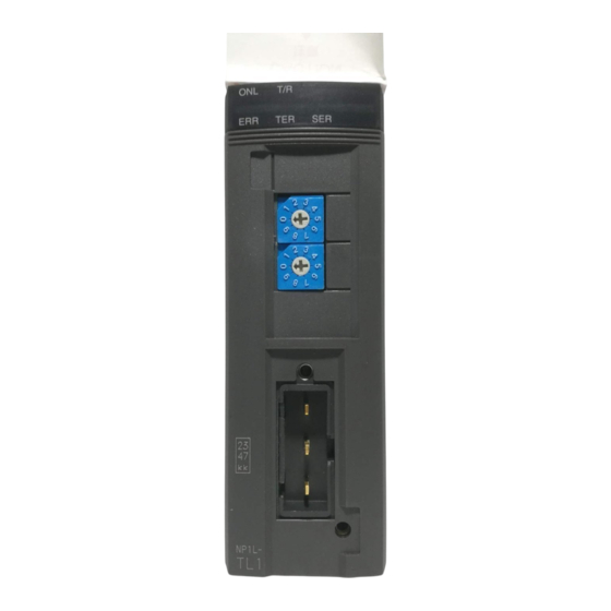
Names and Functions 2-4 Names and Functions 2-4-1 NP1L-TL1 (T-link master module) (1) Names 1) Status indication LED Not used (fixed to 0) 2) T-link station No. selection switch 4) Nameplate (on the right side) 3) T-link connector 5) Version No. (2) Functions 1) Status indication LED This LED indicates the NP1L-TL1 operation status. - Page 21 Names and Functions 2-4 Names and Functions 2) T-link station No. selection switch 0: Normal mode 1: T-link expansion mode 2: I/O expansion mode 3 to 9: Not used Note: As for T-link expansion , I/O expansion mode, see section 1-5. 3) T-link connector This connector is used to connect the T-link connector.
-
Page 22: Np1L-Rt1 (T-Link Interface Module)
Names and Functions 2-4 Names and Functions 2-4-2 NP1L-RT1 (T-link interface module) (1) Names 1) Status indication LED 2) T-link station No. selection switch 4) Nameplate (on the right side) 3) T-link connector 5) Version No. (2) Functions 1) Status indication LED This LED indicates the NP1L-RT1 operation status. - Page 23 Names and Functions 2-4 Names and Functions 2) T-link station No. selection switch This switch is used to specify the T-link station number. Range: 00 to 99 x 10 3) T-link connector This connector is used to connect the T-link connector. The tightening torque for the connector fixing screw must be between 0.9 to 1.0 N •...
-
Page 24: Np1L-Ts1 (T-Link Slave Module)
Names and Functions 2-4 Names and Functions 2-4-3 NP1L-TS1 (T-link slave module) (1) Names 1) Status indication LED 2) T-link station No. selection switch 4) Nameplate (on the right side) 3) T-link connector 5) Version No. (2) Functions 1) Status indication LED This LED indicates the NP1L-TS1 operation status. - Page 25 Names and Functions 2-4 Names and Functions 2) T-link station No. selection switch This switch is used to specify the T-link station number. Range: 00 to 99 x 10 3) T-link connector This connector is used to connect the T-link connector. The tightening torque for the connector fixing screw must be between 0.9 to 1.0 N •...
-
Page 26: Dimensions
Dimensions 2-5 Dimensions The dimensions of NP1L-TL1, NP1L-RT1 and NP1L-TS1 are identical. [in mm] (45) 34.8 Note: When the module is used as the end terminal of the T-link, a T-link terminating resistor must be attached. When the resistor is attached, an approximately 22 mm to 24 mm protrusion is added. -
Page 27: Section 3 System Configuration
Section 3 System Configuration Page 3-1 Mounting Restrictions ..................... 3-1 3-1-1 Mounting position ....................... 3-1 (1) T-link master module/T-link slave module .................... 3-1 (2) T-link interface module ........................3-2 3-1-2 Number of mountable modules ..................3-3 3-2 T-link System Configuration ..................3-4 3-2-1 Basic system configuration .................... -
Page 28: Mounting Restrictions
Mounting Section 3 System Configuration 3-1 Mounting Restrictions 3-1-1 Mounting position (1) T-link master module/T-link slave module T-link master module and T-link slave module can be mounted on the following slots: any slot except the power module mounting slot (two slots from the left on the base board). <8/11/13-slot base board>... -
Page 29: T-Link Interface Module
3-1 Mounting Restrictions Mounting (2) T-link interface module Only one unit of NP1L-RT1 can be mounted on one base board. NP1L-RT1 must be mounted on the right side of the power supply module. In general, modules mountable on NP1L-RT1 base are of “Direct I/O” module type only. (However, the following I/O modules cannot be mounted.) NP1X3206-A, NP1Y32T09P1-A, NP1AX08-MR, NP1AX08V-MR, NP1AX08I-MR <Notes on mounting slave module on NP1L-RT1 base board>... -
Page 30: Number Of Mountable Modules
Mounting 3-1 Mounting Restrictions 3-1-2 Number of mountable modules Maximum 8 units of T-link master module and T-link slave module can be mounted in one configuration. However, when other I/ O master or slave modules, such as OPCN-1 and DeviceNet master or slave modules, are installed, this limit of 8 units applies to the total including them. -
Page 31: T-Link System Configuration
Basic System Configuration 3-2 T-link System Configuration 3-2-1 Basic system configuration Connecting one NP1L-TL1 master module with the MICREX-SX series SX bus (on the base board) enables one T-link system configuration to be constructed. <Example of system configuration> NP1L-TL1 Power * Connect the T-link terminating resistor (100Ω) supply SX bus... -
Page 32: I/O Address Assignment
Address Assignment 3-2 T-link System Configuration 3-2-2 I/O address assignment T-link device is assigned to the I/O area of the CPU. Assigned address differs between Normal mode and T-link expansion mode. (1) Normal mode T-link master module SX bus station No. 1 Mode selection switch: 0 T-link interface module T-link group-type... - Page 33 Address Assignment 3-2 T-link System Configuration <Address number assignments> The address of each I/O module mounted on the T-link group type I/O device needs the T-link station number and the word number which indicates the order in the device. Example: In the sample system configuration shown at the bottom of the previous page, the address of the bit 32 position of the 32-point input module ( the module at far right) on the T-link group type I/O device would be expressed as follows: <Example of D300win>...
-
Page 34: T-Link Expansion Mode, I/O Expansion Mode
Address Assignment 3-2 T-link System Configuration (2) T-link expansion mode, I/O expansion mode T-link master module “1” SX bus station No. Mode selection switch: 1 or 2 T-link interface module T-link group-type I/O device “04” T-link station No. “01” T-link station No. T-link remote station T-link remote station 32 points Input... - Page 35 Address Assignment 3-2 T-link System Configuration <Cautionary note on the concept of even addresses> To use I/O address on T-link by allocating it to a double word (array and structure including 32bit length data) such as DINT and DWORD, observe the following precautions according to the modes (normal mode, T-link expansion mode, and I/O expansion mode) of the T-link master.
- Page 36 Address Assignment 3-2 T-link System Configuration 2) T-link expansion and I/O expansion modes You need to configure the unit which carries out double word access so that the unit has an even number from the beginning by arranging all units connected to the T-link system in youngest to oldest order of addresses ("Address arranged from the front" in the table below is even).
-
Page 37: Communication System With Other Series Using T-Link Slaves
3-2 T-link System Configuration T-link Slave System 3-2-3 Communication system with other series using T-link slaves Data can be transferred through T-link between MICREX-SX series SPH CPUs and MICREX-F series or FLEX-PC series CPUs. (1) Example of connection to MICREX-F55 series when MICREX-SX series CPU becomes a master The MICREX-SX series CPU is the master, and the MICREX-F55 series CPU is a slave. -
Page 38: Example Of Connection To Micrex-F55 Series When Micrex-Sx Series Cpu Becomes A Slave
T-link Slave System 3-2 T-link System Configuration (2) Example of connection to MICREX-F55 series when MICREX-SX series CPU becomes a slave The MICREX-F55 series CPU is the master, and the MICREX-SX series CPU is a slave. MICREX-F55 series T-link slave module T-link master card NP1L-TS1 NV1L-TL1... -
Page 39: T-Link System Using The T-Link Electric Repeater/Converter
Extension of the T-link Transmission 3-2 T-link System Configuration Distance 3-2-4 T-link system using the T-link electric repeater/converter (1) Overview of the T-link Electric Repeater (FRC200A-C10) The FRC200A, with the functions listed below, allows flexible T-link network configurations. • Extension of the T-link transmission distance Two repeaters can be used for one T-link system. -
Page 40: Examples Of System Configurations
Extension of the T-link Transmission 3-2 T-link System Configuration Distance (4) Examples of system configurations 1) One repeater/converter in series TL1 : T-link master module The symbol * indicates a place TK : T-link slave station to which a terminating resistor is to be connected. -
Page 41: System Configuration Using The T-Link Optical Converter
Extension of the T-link Transmission 3-2 T-link System Configuration Distance 3-2-5 System configuration using the T-link optical converter The allowable length of the T-link can be extended using optical transmission lines. Optical transmission lines are minimally affected by noise, thus optical transmission lines provide transmission lines suitable for use with noise-generating devices. (1) Overview of the T-link optical converter There are two types of T-link optical converter available: simple type FNC120A and high performance type FNC130A. -
Page 42: System Configuration
Extension of the T-link Transmission 3-2 T-link System Configuration Distance (2) System configuration System configurations with optical converters are as follows: 1) 1: 1 connection.... Basic system using two optical converters. 2) Cascade connection..System with optical converters connected in series. 3) Star connection... - Page 43 Extension of the T-link Transmission 3-2 T-link System Configuration Distance 2) Cascade connection <When FNC120A is used> This system connects electrical transmission lines and optical transmission lines alternately in series. This system can contain up to 16 optical converters. Symbol *indicates a place to which a terminating resistor Optical cable (1) is to be connected.
- Page 44 Extension of the T-link Transmission 3-2 T-link System Configuration Distance 3) Star connection A star T-link system can be constructed by connecting optical converters to electric transmission lines (up to 8 routes). <When FNC120A is used> Symbol * indicates a place to which a terminating resistor is to be connected.
- Page 45 Extension of the T-link Transmission 3-2 T-link System Configuration Distance 4) Loop connection (FNC120A or FNC130A) The loop connection efficiently implements redundant optical transmission lines. By looping the optical transmission lines, transmission continues even if a part of the optical cable line is disconnected. Symbol * indicates a place to which a terminating resistor is to be connected.
-
Page 46: Maximum Number Of T-Link Connected I/O Stations
Extension of the T-link Transmission 3-2 T-link System Configuration Distance 3-2-6 Maximum number of T-link connected I/O stations Generally speaking, maximum number of T-link connected I/O stations for one T-link master is 32. However, depends on version combination of T-link master and loader, it can be expanded to 64. Here explains calculation of number of T-link connected I/O stations and system configuration for this application. -
Page 47: Section 4 System Definitions
Section 4 System Definitions Page 4-1 System Configuration Definition ................4-1 4-1-1 Registration of module ....................... 4-2 4-1-2 I/O group setting ........................ 4-9 4-2 Fail-soft Setting ...................... 4-10 4-3 Output Hold Definition ................... 4-12... -
Page 48: System Configuration Definition
System Configuration Definition Section 4 System Definitions To construct a T-link system in the MICREX-SX series SPH, the system definitions listed below are required. • System configuration definition (always needed) • Fail-soft setting • Output hold definition Register modules to be used such as CPU modules, T-link master modules, and T-link interface modules, or T-link device with “System_Definition”... -
Page 49: Registration Of Module
System Configuration Definition 4-1 System Configuration Definition 4-1-1 Registration of module How to register modules is described below, taking the sample system configuration described on the preceding page for example. ◊ In the initial condition of the system definition dialog box, a power module (AC power supply of 2-slot specification) and a CPU module selected with the template are registered for a 11-slot base board, as shown below. - Page 50 System Configuration Definition 4-1 System Configuration Definition ◊ Then, the T-link master module that is mounted next to the CPU module is registered. With the CPU module highlighted, click the [Insert] button on the system configuration registration window. The [Module insert] dialog box is displayed. On this dialog box, select “I/O master”...
- Page 51 4-1 System Configuration Definition System Configuration Definition ◊ Then, the T-link device, which is to be connected to the T-link master module, is registered. With the T-link master module highlighted, click the [Insert] button. The [Module insert] dialog box is displayed. Select “Slave”...
- Page 52 4-1 System Configuration Definition System Configuration Definition ◊ Then, the I/O module on the T-link group-type unit is registered. With the T-link interface module highlighted, click the [Insert] button to display the [Module insert] dialog box. To register the I/ O module on the T-link interface I/O group-type unit, select “Remote I/O"...
- Page 53 System Configuration Definition 4-1 System Configuration Definition ◊ After the remaining I/O modules on the T-link interface group-type unit are registered in the same way, T-link capsule type unit is registered. With the T-link interface module highlighted, click the [OK] button. The [Module insert] dialog box is displayed. ◊...
- Page 54 System Configuration Definition 4-1 System Configuration Definition ◊ After registering the number of I/O words occupied by T-link capsule, click the [OK] button. You return to the [Module insert] dialog box. When the [OK] button is clicked on this dialog box, the T-link capsule is registered. <Registering T-link I/O group-type unit FTL for MICREX-F series>...
- Page 55 System Configuration Definition 4-1 System Configuration Definition <Registration of T-link slave module> The T-link slave module, or NP1L-TS1, sends/receives data to/from the PLC system working as a T-link master station by means of I/O communication. The number of occupied I/O words that are used for this communication is set by parameter when the module is registered.
-
Page 56: I/O Group Setting
I/O Group Setting 4-1 System Configuration Definition 4-1-2 I/O group setting I/O group is set for the module that is already registered to the system configuration. ◊ On the [Module property] dialog box for the CPU module, click the [Parameter…] button. The [CPU parameter] dialog box is displayed. -
Page 57: Fail-Soft Setting
Fail-soft Setting 4-2 Fail-soft Setting “Fail-soft operation” means to have normal modules/capsules continue their operation even if an error occurs in an I/O module/ capsule on the SX bus or T-link. Set “Fail-soft operation” using the “Fail-soft setting” in the CPU module parameter. <Setting procedure>... - Page 58 Fail-soft Setting 4-2 Fail-soft Setting <Key-point> • As for the modules on SX bus, the CPU does not start operation if the modules registered to the system configuration definition are not started up when the system is powered up. However, when fail-soft operation is set for the modules or units on T-link remote I/O, the CPU starts operation in "nonfatal fault”...
-
Page 59: Output Hold Definition
Output Hold Definition 4-3 Output Hold Definition To hold the state which existed immediately before a system fault that stops CPU module operation, or to hold the output immediately before the CPU module stops, use the output hold facility. Set the “Output hold” setting using the “Individual output hold station definition” parameter on the T-link master module. <Operating procedure>... - Page 60 Output Hold Definition 4-3 Output Hold Definition ◊ When the [Parameter…] button is clicked, the [T Link master parameter setting] dialog box is displayed. On this dialog box, “output hold” is registered for individual T-link station. For the stations, for which you want to set “output hold”, click the buttons that correspond to their T-link station numbers to set them ON.
-
Page 61: Section 5 Wiring
Section 5 Wiring Page 5-1 Precautions ......................5-1 5-2 T-link Wire Assembling .................... 5-2... - Page 62 Precautions Section 5 Wiring 5-1 Precautions (1) Before removing the connector, remove the fixing screws. (2) T-link cables must be isolated from high-voltage cables and power cables as far as possible. T-link cables must not be run parallel with those cables. (3) These cables should be installed as shown in the following figure.
-
Page 63: T-Link Wire Assembling
T-link Wire Assembling 5-2 T-link Wire Assembling Process the end of a twisted pair cable as shown below. 1) Remove a part of the sheath 2) Attach crimp terminals. and internal insulation. Apply the insulation tube before caulking the terminal. Note:If wires are connected directly to the terminal block without using crimp terminals, connection failure may result and T-link... -
Page 64: Section 6 Troubleshooting
Section 6 Troubleshooting Page 6-1 LED Indication in Various System Conditions ............6-1 6-2 System Memory ....................... 6-2 (1) I/O module fault (%MX10.2.5 (D300win), SM25 (Standard loader)) ........... 6-2 (2) Remote I/O master initialization error (%MX10.25.0~7 (D300win), SM250~7 (Standard loader)) ..6-2 (3) Remote I/O master - I/O module configuration/fault ................ -
Page 65: Led Indication In Various System Conditions
Section 6 Troubleshooting The T-link master module, or NP1L-TL1, continuously monitors the T-link system that is controlled by the local module and the master module. In case of error, the content of occurred error is indicated by means of the LEDs provided on the module as well as notified to the SX series CPU module. -
Page 66: System Memory
6-2 System Memory The system memory area in the CPU module contains flags for remote I/O masters. By checking these flags, you can monitor the status of T-link. (1) I/O module fault (%MX10.2.5 (D300win), SM25 (Standard loader)) When an I/O module or remote I/O module on the SX bus that has been registered with an “I/O group” in the CPU module, but not registered for the fail-soft setting, has a fault, the CPU module stops its operation. -
Page 67: Remote I/O Master - I/O Module Configuration/Fault
6-2 System Memory (3) Remote I/O master - I/O module configuration/fault Remote I/O master-I/O module configuration When T-link devices connected with a T-link master are g i f o i t normal or in a fault state, flags for corresponding T-link station numbers are turned on. - Page 68 6-2 System Memory <Flag assignment> The following tables show an example of flag assignment using the remote I/O master - I/O module configuration fault. Assignment for remote I/O masters 1 to 7 are handled in the same manner. < > <...
-
Page 69: Diagnosing The Status By Loader
6-3 Diagnosing the Status by Loader With the fault diagnostic function of the program loader, you can read the following information: ] s i → i l i ] s i n i l → i l i ] s i n i l →... - Page 70 6-3 Diagnosing the Status by Loader ◊ When a T-link master module is selected on the system configuration display window, the detail information of the T-link master module is displayed on the detail information display window. ◊ Displayed information can be changed over by clicking the corresponding tab on the detail information display window. 1) [System RAS] tab window 2) [Bus transmission information] tab window...
- Page 71 6-3 Diagnosing the Status by Loader 3) [Dump list] tab window...
-
Page 72: System Ras Information
6-3 Diagnosing the Status by Loader 6-3-1 System RAS information On the [System RAS] tab window, the following information is displayed: • Type information of the T-link master module that is selected on the system configuration display window • Module intensive status of the T-link master module that is selected on the system configuration display window (1) Type information Module type and software version (module firmware version) are displayed. -
Page 73: Sx Bus Transmission Information
6-3 Diagnosing the Status by Loader 6-3-2 SX bus transmission information If SX bus transmission path is affected by noise or if the wiring of SX bus is imperfect, various errors related to SX bus transmission are counted. If one of these error counters shows certain count value, it seems that the environment of the SX system installed place is poor with respect to noise and requires your taking proper measures. -
Page 74: Dump List
6-3 Diagnosing the Status by Loader 6-3-3 Dump list The dump list for this module contains the following information: • Configuration/error flag information • Remote I/O station error information • Remote I/O station intensive status information • T-link transmission information •... -
Page 75: Remote I/O Station Error Information
6-3 Diagnosing the Status by Loader (2) Remote I/O station error information T-link remote station (slave station) error information is displayed. Indicates error occurred station Number of error and the content of occurred occurred stations error (for 32 stations). Error code D1: Remote I/O station configuration mismatch, D2: Remote I/O station disconnected D3 to D7: Communication error (noise, etc.,) D8: Remote I/O station non-fatal error... -
Page 76: T-Link Transmission Information
6-3 Diagnosing the Status by Loader (4) T-link transmission information Stores the error information that has been detected during T-link communication. Using ring file format, maximum 32 generations of error log can be stored. Error counter Error information (see note) +00h Error counter Error information (see note) -
Page 77: On-Board Hardware Error Ras
6-3 Diagnosing the Status by Loader (5) On-board hardware error RAS Indicates the error status of the processor, peripheral ROM or RAM used in the module. Error occurrence in this area means that the module’s hardware has failed, requiring the replacement or repair of the module. 0 0 0 0 0 0 0 0 0 0 0 0 CPU error Not used... -
Page 78: Setting Error Causes
6-3 Diagnosing the Status by Loader (6) Setting error causes Indicates the content of setting error related to system definition. Not used 0 0 0 Number of connected stations error Not used Set ON if the number of remote stations connected to T-link exceeds 32 (64). -
Page 79: Non-Fatal Failure I/O Ras
6-3 Diagnosing the Status by Loader (7) Non-fatal failure I/O RAS Stores remote I/O station address which has non-fatal failure. If there is no non-fatal failure, "FFFF" is stored on top address of this area. +00h +01h End code is added at the end of error code. End code (FFFFh) +40h •... -
Page 80: Type Information
6-3 Diagnosing the Status by Loader (8) Type information Shows Module group type, Type information, Software version No.,etc. 6-16... -
Page 81: Appendix 1 I/O Response Time
Appendix 1 I/O Response Time Page Appendix 1-1 Outline ..................... App.1-1 Appendix 1-2 Input Response Time ..............App.1-1 (1) In case T-link master is set as Normal or T-link expansion mode (Mode 0 or 1) ......App.1-1 (2) In case T-link master is set as I/O expansion mode (Mode 2) ............. App.1-1 Appendix 1-3 Output Response Time .............. -
Page 82: Appendix 1-1 Outline
Appendix 1 I/O Response Time Appendix 1-1 Outline I/O response time may changed depends on number of T-link I/O stations, occupied I/O words, SX-bus tact cycle, program execution time (task time). Also, if message communication is used, or SX-bus communication have error because of noise, response time may have fluctuation. -
Page 83: Appendix 1-4 Detail Of Response Time Parameters
Appendix 1-4 Detail of Response Time Parameters Input delay: Hardware delay time of Input module / capsule. For more detail, see Hardware manual. Output delay: Hardware delay time of Output module / capsule. For more detail, see Hardware manual. T-link cycle: Communication cycle time between T-link master and T-link I/O. It depends number of I/O stations and occupied I/O words. -
Page 84: Appendix 1-5 Example Of Response Calculation
Appendix 1-5 Example of Response Calculation Here shows maximum response time calculation example (suppose, input delay time = 0.7ms, one SPH300 CPU and multiple I/ Os configuration). On below picture; “Capsule type I/O” means FTK, FTT, NR1T or NR2T type I/O. “Building type I/O”... -
Page 85: Case 3: Total Approx. 500 Words I/O For 1 T-Link Master
Appendix 1-5 Example of Response Calculation (3) Case 3: Total approx. 500 words I/O for 1 T-link master • Capsule type I/O 0 unit • 7 Building type I/O. (Assume 6 analog modules for one base board. One analog module occupy 12 words.) Total I/O = 504 words. - Page 86 Gate City Ohsaki, East Tower, 11-2, Osaki 1-chome, Shinagawa-ku, Tokyo, 141-0032,Japan Phone: +81-3-5435-7280 Fax: +81-3-5435-7425 http://www.fesys.co.jp/eng/...
Need help?
Do you have a question about the MICREX-SX SPH Series and is the answer not in the manual?
Questions and answers