
Related Manuals for Fuji Electric OPC-AO


Summary of Contents for Fuji Electric OPC-AO
- Page 1 日 本 語 Fuji Electric Co., Ltd. INR-SI47-1696-JE ...
- Page 2 本書に掲載されている会社名や製品名は,一般に各社の商標または登録商標です。 仕様は予告無く変更することがあります。 No part of this publication may be reproduced or copied without prior written permission from Fuji Electric Co., Ltd. All products and company names mentioned in this manual are trademarks or registered trademarks of their respective holders.
- Page 3 日 本 日本語版 語...
-
Page 5: 安全上のご注意
まえがき アナログ出力インタフェースカードをお買い上げいただき誠にありがとうございます。 この取扱説明書は,アナログ出力インタフェースカード(OPC‑AO)について記載しています。 アナログ出力インタフェースカードを,当社インバータに搭載することにより,アナログ出力(電流を2端子) を使用することが可能となります。 アナログ出力インタフェースカードは, インバータのオプション接続ポート 1 箇所にのみ搭載可能です。 ただし、 OPC‑AIO との同時搭載はできません。 この取扱説明書にはインバータに関する取扱い方の記載はありませんので,ご使用の前には, この説明書とイン バータ本体のユーザーズマニュアルをお読みになって取扱い方を理解し, 正しくご使用ください。 間違った取扱 いは,正常な運転を妨げ,寿命の低下や故障の原因になります。 取扱説明書はご使用後も大切に保管してください。 関連資料 OPC‑AO に関連する資料を以下に示します。目的に応じてご利用ください。 ・ インバータユーザーズマニュアル 資料は随時改訂していますので,ご使用の際には最新版の資料を入手してください。 この取扱説明書に記載している図、端子の有無、機能コード、アラームコード等は対象インバータによって異な る場合があります。 日 本 語 ‑ この取扱説明書を読み,理解したうえで,アナログ出力インタフェースカードの取り付け,接続(配線) , 運転,保守点検を行ってください。 ‑ 間違った取扱いは,正常な運転を妨げたり,寿命の低下や故障の原因になります。 ‑ この取扱説明書は,実際に使用される最終需要家に確実にお届けください。最終需要家はこの取扱説明書 を,アナログ出力インタフェースカードが廃棄されるまで大切に保管してください。 ... - Page 6 取付けおよび配線について ・ 各種スイッチの切換は,電源を遮断し10分以上経過後,チャージランプの消灯を確認し,テスターなどを使用 して主回路端子 P(+)‑N(‑)間の直流中間回路電圧が安全な値(DC+25V 以下)に下がっていることを確認してから 行ってください。 ・ 配線作業は,資格のある専門家が行ってください。 感電のおそれあり ・ 外部あるいは内部部品が損傷・脱落している製品を使用しないでください。 火災,事故,けがのおそれあり ・ 糸くず,紙,木くず,ほこり,金属くずなどの異物がインバータやインタフェースカード内に侵入するのを防止 してください。 火災,事故のおそれあり ・ 製品の取付け,取外し時に不適切な作業を行うと,製品が破損するおそれがあります。 故障のおそれあり ・ インバータ,モータ,配線からノイズが発生します。周辺のセンサーや機器の誤動作に注意してください。 事故のおそれあり 操作運転について ・ 必ずインバータ本体の表面カバーを取り付けてから電源 ON(閉)してください。なお,通電中はカバーを外さな いでください。 ・ 濡れた手でスイッチを操作しないでください。 感電のおそれあり ・ 機能コードのデータ設定を間違えたり,取扱説明書およびユーザーズマニュアルを十分理解しないで機能コード のデータ設定を行うと,機械が許容できないトルクや速度でモータが回転することがあります。インバータの運 転の前に各機能コードの確認,調整を行ってください。 事故のおそれあり 保守点検,部品の交換について ・ 各種スイッチの切換は,電源を遮断し10分以上経過後,チャージランプの消灯を確認し,テスターなどを使用 して主回路端子 P(+)‑N(‑)間の直流中間回路電圧が安全な値(DC+25V 以下)に下がっていることを確認してから 行ってください。 ...
- Page 7 廃棄について ・ 製品を廃棄する場合は,産業廃棄物として扱ってください。 けがのおそれあり その他 ・ 改造は絶対しないでください。 感電,けがのおそれあり 日 本 語 アイコンについて 本書では以下のアイコンを使用しています。 この表示を無視して誤った取扱いをすると, インバータが本来持つ性能を発揮できなかったり, その操 作や設定が事故につながることになります。 本製品の操作や設定の際,知っておくと便利な参考事項を示しています。...
-
Page 8: Table Of Contents
目次 まえがき ........i ■ 安全上のご注意......i 第1章 ご使用の前に ....... 1‑1 1.1 現品の確認 ......1‑1 1.2 使用環境 ......1‑1 1.3 インタフェースカードの取付けと取外し 1‑2 1.3.1 インタフェースカードの取付け ... 1‑2 1.3.2 インタフェースカードの取外し ... 1‑3 1.4 インタフェースカードへの配線 ..1‑4 1.5 インタフェースカード上の端子配列 ..1‑6 第2章 配線 ....... 2‑1 2.1 基本接続図 ......2‑1 2.2 端子機能説明 ......2‑2 2.3 機能コードの設定... -
Page 9: 第1章 ご使用の前に
第1章 ご使用の前に 1.1 現品の確認 開梱し次の項目を確認してください。 (1) インタフェースカード,ねじ(M3×8:2 本),取扱説明書(本書)が入っていることを確認してください。 (2) インタフェースカード上の部品の異常,凹み,反りなど輸送時での破損がないことを確認してください。 (3) インタフェースカード上に形式「OPC‑AO」が印刷されていることを確認してください。 【図 1.1 参照】 製品にご不審な点や不具合などがありましたら,お買い上げ店または最寄りの弊社営業所までご連絡ください。 CN1 ねじ取付け用穴(左) 取外し用つまみ 形式 (表面) (裏面) 取付け位置決め部 ねじ取付け用穴(右) 図 1.1 各部名称 1.2 使用環境 日 本インタフェースカードを含めたインバータは,表 1.1 を満たす使用環境に据え付けてください。 本 表 1.1 使用環境 語 項 目 ... -
Page 10: インタフェースカードの取付けと取外し
1.3 インタフェースカードの取付けと取外し 各種スイッチの切換は,電源を遮断し10分以上経過後,チャージランプの消灯を確認し,テスターなどを使用して 主回路端子 P(+)‑N(‑)間の直流中間回路電圧が安全な値 (DC+25V 以下) に下がっていることを確認してから行ってく ださい。 感電のおそれあり ・ 外部あるいは内部部品が損傷・脱落している製品を使用しないでください。 火災,事故,けがのおそれあり ・ 糸くず,紙,木くず,ほこり,金属くずなどの異物がインバータやインタフェースカード内に侵入するのを防止 してください。 火災,事故のおそれあり ・ 製品の取付け,取外し時に不適切な作業を行うと,製品が破損するおそれがあります。 故障のおそれあり 1.3.1 インタフェースカードの取付け インバータ本体の主回路端子および制御回路端子の配線は,インタフェースカードを取り付ける前に 行ってください。 (1) インバータ本体の表面カバーを取り外し, 制御プリント基板を露出してください。 インタフェースカードは, インバータ本体のオプション接続ポートに取付け可能です。ただし、OPC‑AIO との同時搭載はできません。 インバータ取扱説明書の「配線」を参照してカバーを取り外してください。 (2) インタフェースカードの裏面(図 1.1)の CN1 を,インバータ本体の制御プリント基板の接続ポートへ差し 込み,付属ねじで固定してください。 (図 1.3) ... -
Page 11: インタフェースカードの取外し
① カードをツメに引っ掛けるようにしながらイン バータ本体へ位置決めする。 ② コネクタをインバータ本体へ挿入する。 注: 先 にコネクタ側を挿入した場合,挿入が不十分で 接触不良となる可能性あります。 ② ① ツメ FRENIC‑MEGA 図 1.2 カードの取付け( B‑port 取付け時) 日 本 語 (取外し用つまみ) FRENIC‑MEGA 図 1.3 取付け完了( B‑port 取付け時) 1.3.2 インタフェースカードの取外し インタフェースカードを取外す際は,ねじを2ヶ所外し,取外し用つまみ(上図を参照)を引っぱって取り外し てください。 1‑3 ... -
Page 12: インタフェースカードへの配線
1.4 インタフェースカードへの配線 ・ 各種スイッチの切換は,電源を遮断し10分以上経過後,チャージランプの消灯を確認し,テスターなどを使用 して主回路端子 P(+)‑N(‑)間の直流中間回路電圧が安全な値(DC+25V 以下)に下がっていることを確認してから 行ってください。 ・ 配線作業は,資格のある専門家が行ってください。 感電のおそれあり ・ 一般的に制御信号線の被覆は強化絶縁されていませんので,主回路活電部に制御信号線が直接触れると,何らか の原因で絶縁被覆が破壊されることがあります。この場合,制御信号線に主回路の高電圧が印加される危険性が ありますので,主回路活電部に制御信号線が触れないように注意してください。 事故のおそれあり,火災のおそれあり ・ インバータ,モータ,配線からノイズが発生します。周辺のセンサーや機器の誤動作に注意してください。 事故のおそれあり 基本接続図(第2章の図 2.1)および図 1.4 の配線例を参考に,以下の注意事項を守ってインタフェースカード への配線を行ってください。 (1) 電源を OFF(開)してください。 (2) インタフェースカードへの配線にはシールド線を使用してください。 (3) インタフェースカードへの配線は,ノイズによる誤動作を防止するため,インバータ本体の主回路配線およ びその他の動力線とはできるだけ離し,同一ダクト内に入れないでください。 (4) インバータの電源投入前に配線を完了してください。 (5) インタフェースカードの接続端子台の仕様を表 1.2 に示します。 表 1.2 端子仕様 項目 仕様 AWG18(0.75mm ) ... - Page 13 線種,配線本数によっては,インバータの表面カバーが浮き上がり,タッチパネルが正しく動作しな い場合があります。その際は,線種・線径等の変更が必要です。 配線は,制御プリント基板上を極力這わないよう,図 1.4 のように配線してください。誤動作の原因 になることがあります。 シールド線をアースに接続する場合は,被 覆付の丸形端子 R1.25‑3 等を使用して,こ のねじに共締めしてください。 シールド線のアース接続箇所 日 本 語 * インタフェースカードからの配線は, インバータ本体の制御端子台 上部と表面カバーの間を通してください。 FRENIC‑MEGA 0.4kW の例 ...
-
Page 14: インタフェースカード上の端子配列
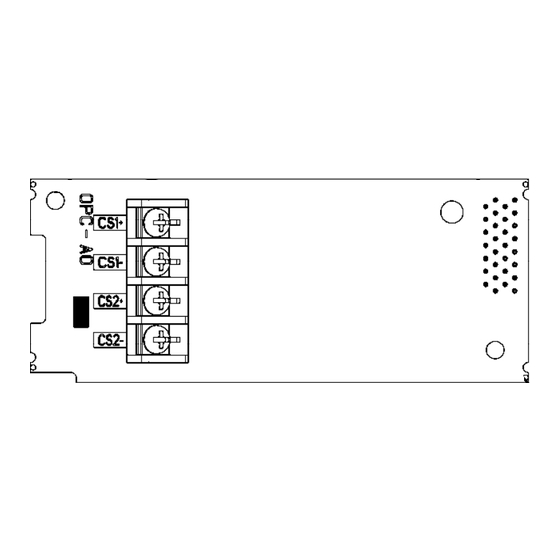
1.5 インタフェースカード上の端子配列 CS1+ CS1- CS2+ CS2- 図 1.5 端子配列 1‑6 ... -
Page 15: 第2章 配線
第2章 配線 2.1 基本接続図 インバータ L1/R U L2/S V L3/T W OPC‑AO +24VDC CS1+ 日 ア CS1‑ 本 ナ ロ 語 アナログ電流計 グ 出 CS2+ 力 CS2‑ アナログ電流計 CM 図 2.1 基本接続図 2‑1 ... -
Page 16: 端子機能説明
2.2 端子機能説明 端子機能一覧を表 2.1 に示します。 表 2.1 端子機能一覧 区 端子 分 端子機能説明 端子名称 記号 CS1+ アナログ アナログ直流電流 DC4〜20mA のモニタ信号を出力します。信号内容につい 電流出力+ ては、 「2.3 機能コード設定」を参照下さい。 CS2+ (2) ハード仕様 *出力電流:DC4〜20mA *接続可能インピーダンス : 最大 500Ω (DC4〜20mA 出力時) *分解能 : 1/3000 *ゲイン調整範囲 : 0〜300% <制御回路部> DC24V 電流源 ア ナ 電流 ロ CS1+ グ 出... -
Page 17: 機能コードの設定
2.3 機能コードの設定 2.3.1 機能コードの設定(MEGA) 本インタフェースカードに関連する機能コードを表 2.2 に示します。 (機能コード o71,o72,o74,o75 はインタフェースカードを本体へ接続することにより設定可能になります。 ) 表 2.2 機能コード設定(MEGA) 制御方式 ※1 ※2 ※3 運 デ 工 転 ー 場 機能 中 タ 出 名 称 設定可能範囲 変 コ 荷 コード PG V/f PG 更 ピ 値 レス ... -
Page 18: 機能コードの設定(Hvac/Aqua
2.3.2 機能コードの設定(HVAC/AQUA) 本インタフェースカードに関連する機能コードを表 2.3 に示します。 機能コードの詳細については、ユーザーズマニュアルを参照願います。 表 2.3 機能コード設定(HVAC/AQUA) 機能 機能 名称 名称 コード コード o90 端子【CS2】 AO 機能選択 o96 端子【CS1】 AO 機能選択 o91 ゲイン調整【CS2】 o97 ゲイン調整【CS1】 日 本 語 2‑4 ... -
Page 19: 機能コード詳細
2.4 機能コード詳細 各機能コードの詳細説明を以下に示します。 2.4.1 機能コード詳細(MEGA) ■ CS2,CS1 機能選択(o71,o74) 端子 CS2,CS1 で設定する機能を選択します。 表 2.4 機能コード詳細(MEGA) o71 o74 機能名称 機能説明 0 0 出力周波数 1(滑り補償前) 4〜20mA/0〜+100% 1 1 出力周波数 2(滑り補償後) * 100%=最高周波数 4〜20mA/0〜+200% 2 2 出力電流 * 100%=インバータ定格出力電流 200V 系:4〜20mA/0〜+250V 3 3 出力電圧 400V 系:4〜20mA/0〜+500V 4〜20mA/0〜+200% 4 4 出力トルク * 100%=モータ定格トルク 4〜20mA/0〜+200% 5 5 負荷率 * 100%=モータ定格負荷 ... -
Page 20: 第3章 I/O チェック
第3章 I/O チェック プログラムモードの「I/O チェック」によって,外部信号の入出力信号の状態をタッチパネルのモニタに表示で きます。操作方法については、インバータの取扱説明書又はユーザズマニュアルの「入出力信号状態をチェック する」を参照して下さい。 日 本 語 3‑1 ... -
Page 21: 第4章 アラーム保護機能
第4章 アラーム保護機能 er4 オプション通信エラー( ) 現象 アナログ出力インタフェースカードとインバータ本体間の通信エラーが発生した。 原因 チェックと対策 (1) インタフェースカードと インタフェースカードのコネクタとインバータ本体のコネクタが正しく嵌 インバータ本体の接続に 合しているかを確認する。 不具合がある インタフェースカードを正しく本体に装着する。 (2) 周囲から強いノイズを受 ノイズ対策 (接地の状態, 信号線や通信ケーブル/主回路配線の設置方法な けた ど)を確認する。 ノイズ対策を改善する。 (3) 同一インタフェースカー 同一インタフェースカードが 2 枚以上搭載されていないか確認する。 ドが 2 枚以上搭載されてい インバータ 1 台に対し,同一インタフェースカードは 1 枚のみとする。 る インタフェースカードが搭載されていても機能コードの o コード(オプション機能)が表示されない 場合は,... - Page 22 MEMO ...
-
Page 23: English Version
English Version... -
Page 25: Preface
Preface Thank you for purchasing our analog output interface card. This instruction manual describes the analog output interface card "OPC-AO" designed for the inverter series of inverters. Mounting the analog output interface card on your inverter enables analog input (voltage and current for each terminal) and analog output (voltage and current for each terminal) to/from the inverter. -
Page 26: Installation And Wiring
Installation and wiring • Before changing the switches, turn OFF the power and wait at least 10 minutes. Make sure that the charging lamp is turned OFF. Further, make sure, using a multimeter or a similar instrument, that the DC link bus voltage between the terminals P(+) and N(-) has dropped to the safe level (+25 VDC or below). - Page 27 Disposal • Treat the interface card as an industrial waste when disposing of it. Otherwise injuries could occur. Others • Never modify the interface card. Doing so could cause an electric shock or injuries. ...
- Page 28 Table of Contents Preface ....................i ■ Safety precautions................i Chapter 1 BEFORE USING THIS OPTION .........1-1 1.1 Acceptance Inspection ..............1-1 1.2 Operating Environment .............1-1 1.3 Installation and Removal of the Interface Card ......1-2 1.3.1 Installing the interface card..........1-2 1.3.2 Removing the interface card ..........1-3 1.4 Wiring ..................1-4 1.5 Terminal Allocation and Symbol Diagram .........1-6 Chapter 2 WIRING................2-1...
-
Page 29: Chapter 1 Before Using This Option
(2) The interface card is not damaged during transportation--no defective parts, dents or warps. (3) The model name "OPC-AO" is printed on the interface card. (See Figure 1.1.) If you suspect the product is not working properly or if you have any questions about your product, contact the shop where you bought the product or your local Fuji branch office. -
Page 30: Installation And Removal Of The Interface Card
1.3 Installation and Removal of the Interface Card Before changing the switches, turn OFF the power and wait at least 10 minutes. Make sure that the charging lamp is turned OFF. Further, make sure, using a multimeter or a similar instrument, that the DC link bus voltage between the terminals P(+) and N(-) has dropped to the safe level (+25 VDC or below). -
Page 31: Removing The Interface Card
Fit the positioning cutout of the card over the tab on the inverter to determine the mounting position. Insert connector CN1 on the interface card into the option connection ports on the inverter's control PCB. Note: Be sure to follow the order of Inserting first lead... -
Page 32: Wiring
1.4 Wiring Before changing the switches, turn OFF the power and wait at least 10 minutes. Make sure that the charging • lamp is turned OFF. Further, make sure, using a multimeter or a similar instrument, that the DC link bus voltage between the terminals P(+) and N(-) has dropped to the safe level (+25 VDC or below). • Qualified electricians should carry out wiring. Otherwise, an electric shock could occur. - Page 33 Depending upon the wire type and the number of wires used, the front cover may be lifted by the wires, which impedes normal keypad operation. If it happens, change the wire type or size. Route the wires, taking care not to let them go over the control PCB, as shown in Figure 1.4. Otherwise, malfunctions may occur.
- Page 34 1.5 Terminal Allocation on the Interface Card CS1+ CS1- CS2+ CS2- Figure 1.5 Terminal Allocation and Symbol Diagram...
-
Page 35: Chapter 2 Wiring
Chapter 2 WIRING 2.1 Connection Diagram INVERTER L1/R L2/S L3/T OPC‑AO +24VDC CS1+ CS1‑ Analog meter CS2+ CS2‑ Analog meter CM Figure 2.1 Connection Diagram... -
Page 36: Terminal Functions
2.2 Terminal Functions Table 2.1 Terminals and Their Specifications Functions Symbol Name CS1+ Analog (1) Outputs the monitor signal of analog DC current (4 to 20 mA DC). Please refer current to "2.3 Configuring Inverter's Function Codes" for the contents of a signal. CS2+ output (+) ... -
Page 37: Configuring Inverter's Function Codes
2.3 Configuring Inverter's Function Codes 2.3.1 Configuring Inverter's Function Codes (MEGA) Table 2.2 lists the function codes related to the analog input/output interface card. (Function codes o71, o72,o74 and o75 become available when the interface card is connected to the inverter.) Table 2.2 Function Codes and Parameters (MEGA) Drive control Function... - Page 38 2.3.2 Configuring Inverter's Function Codes (HVAC/AQUA) Table 2.3 lists the function codes related to the analog input/output interface card. For details about these function codes, refer to User's Manual. Table 2.3 Function Codes (HVAC/AQUA) Function Function Name Name code code Terminal [CS2] Function Terminal [CS1] Function (Gain to output current)
-
Page 39: Function Codes Details
2.4 Function Codes Details This section details the function codes. 2.4.1 Function Codes Details (MEGA) Terminal [CS2,CS1] function (o71 and o74) Configure function codes o71 and o74 to assign functions to terminals [CS2] and [CS1]. Table 2.4 Function Codes Details (MEGA) Function Description 4 to 20 mA/0 to +100%... -
Page 40: Chapter 3 I/O Checking
Chapter 3 I/O CHECKING "I/O Checking" in your inverter program mode displays the I/O status of external signals on the monitor of the keypad. efer to "I/O Checking" of the inverter Instruction Manual user's manual for the operation method. ... -
Page 41: Chapter 4 Protective Function
Chapter 4 PROTECTIVE FUNCTION Option communications error ( Problem A communications error occurred between the analog output interface card and the inverter. Possible Causes What to Check and Suggested Measures (1) There is a problem with the Check whether the connector on the interface card is firmly engaged with that of connection between the the inverter. - Page 42 MEMO ...
- Page 43 In no event will Fuji Electric Co., Ltd. be liable for any direct or indirect damages resulting from the application of the information in this manual. ...
- Page 44 富士電機株式会社 Fuji Electric Co., Ltd. パワエレ機器事業本部 ドライブ事業部 Gate City Ohsaki, East Tower, 11-2, Osaki 1-chome, 〒141-0032 東京都品川区大崎一丁目 11 番 2 号 Shinagawa-ku, Tokyo, 141-0032, Japan (ゲートシティ大崎イーストタワー) Phone: +81 3 5435 7283 Fax: +81 3 5435 7425 URL http://www.fujielectric.co.jp/...
Need help?
Do you have a question about the OPC-AO and is the answer not in the manual?
Questions and answers