Fuji Electric MICREX-SX SPH Series User Manual
General purpose communication module
Hide thumbs
Also See for MICREX-SX SPH Series:
- User manual (135 pages) ,
- User manual (20 pages) ,
- User manual (86 pages)
Table of Contents
Advertisement
Quick Links
See also:
User Manual
Advertisement
Table of Contents

Related Manuals for Fuji Electric MICREX-SX SPH Series


Summary of Contents for Fuji Electric MICREX-SX SPH Series
- Page 1 series USER'S MANUAL General Purpose Communication Module Type: NP1L-RS1 (RS-232C: 1CH, RS-485: 1CH) NP1L-RS2 (RS-232C: 1CH) NP1L-RS3 (RS-232C: 2CH) NP1L-RS4 (RS-485: 1CH) NP1L-RS5 (RS-485: 2CH) FEH225d...
- Page 2 *This manual is structured to be applicable to both D300win and Standard Loader. *In addition to the above manuals, the following Fuji Electric FA Components & Systems Co., Ltd. site offers various manuals and technical documents associated with MICREX-SX.
- Page 3 Safety Precautions Be sure to read the “Safety Precautions” thoroughly before using the module. Here, the safety precaution items are classified into “Warning” and “Caution.” Warning Incorrect handling of the device may result in death or serious injury. Caution Incorrect handling of the device may result in minor injury or physical damage. Even some items indicated by “Caution”...
- Page 4 Do not attempt to change system configurations (such as installing or removing I/O modules) while the power is ON, otherwise, failure or erratic operation might occur. Do not attemp to repair the module by yourself contact your Fuji Electric agent. When replacing the batteries, correctly and securely connect the battery connectors, otherwise, fire, accidents or failure might occure.
- Page 5 Revisions c i f • r i f y t i • • S " " . ) • 6 " " d • • c i f " r " r P " " r • • • • •...
-
Page 6: Table Of Contents
Contents Preface Safety Precautions Revisions Contents Page Section 1 General ..................1-1 1-1 General ............................1-1 1-2 Selections and Programs for the Communication ..............1-2 1-3 General Purpose Communication Package for Factory Automation Machine ......1-3 1-4 Product Versions and Supported Functions ................1-4 1-4-1 Supported functions .......................... - Page 7 Contents Page 4-3 Initialization ............................. 4-7 4-3-1 Initialization parameters ........................4-7 4-3-2 Initialization procedure ........................4-10 4-3-3 OPEN status list ..........................4-10 4-4 Data Sending ..........................4-11 4-4-1 Data sending procedure ........................4-11 4-4-2 Send status list ............................ 4-12 4-5 Data Receiving ..........................4-13 4-5-1 Data receiving procedure ........................
- Page 8 Contents Page Appendix 2-3-7 Individual Start of CPU ....................App.2-8 Appendix 2-3-8 Individual Initialization Start of CPU ................App.2-8 Appendix 2-3-9 Individual Stop of CPU ....................App.2-9 Appendix 2-3-10 Individual Reset of CPU ....................App.2-9 Appendix 3 Additional Explanation for NP1L-RS3 ......App.3-1 Appendix 3-1 Applicable Version for NP1L-RS3 ................
-
Page 9: Section 1 General
Section 1 General Page 1-1 General ......................... 1-1 1-2 Selections and Programs for the Communication ........... 1-2 1-3 General Purpose Communication Package for Factory Automation Machine ..1-3 1-4 Product Versions and Supported Functions ............1-4 1-4-1 Supported functions ......................1-4 1-4-2 Available standard extended FB ................... -
Page 10: Section 1 General
Section 1 General General 1-1 General NP1L-RS1/2/4 are communication modules which enable data communication between a CPU module and external devices, and which are connected to the base board (on the SX bus) of MICREX-SX series. (NP1L-RS1/2/4 are sometimes abbreviated as RS1/2/4.) The port type and the number of ports are as follows: RS-232C (1:1) -
Page 11: Selections And Programs For The Communication
1-2 Selections and Programs for the Communication The following preparations are necessary for RS1/2/4 to communicate between a CPU module of MICREX-SX series and external devices. MICREX-SX series RS1/2/4 Power CPU I/O supply <CPU modules side> <RS1/2/4 side> Initializing parameters for a RS-232C port and a Selection switch of the module is used. -
Page 12: General Purpose Communication Package For Factory Automation Machine
1-3 General Purpose Communication Package for Factory Automation Machine Nonsequenced FB is provided for NP1L-RS1/2/4 to communicate with external serial devices. (Included in D300win.) General purpose communication package for Factory Automation machine (NP4N-COMF) is provided to communicate with specified external serial devices. NP4N-COMF includes following function blocks. -
Page 13: Product Versions And Supported Functions
1-4 Product Versions and Supported Functions For the general purpose communication module, supported functions and available FBs depend on the product version. 1-4-1 Supported functions Note 2: : supported : Not supported i l r i l r i l r —... -
Page 14: Section 2 Specifications
Section 2 Specifications Page 2-1 General Specifications ....................2-1 2-2 Communication Specifications ................. 2-2 2-3 Names and Functions ....................2-3 2-3-1 Names ........................... 2-3 (1) NP1L-RS1 ............................... 2-3 (2) NP1L-RS2 ............................... 2-3 (3) NP1L-RS4 ............................... 2-4 2-3-2 Functions ..........................2-4 2-4 Dimensions ........................ -
Page 15: General Specifications
General specifications Section 2 Specifications 2-1 General Specifications ° C ° C v i t y t i l l o y t i i t l i l p µ n i l y t i ± c i t ±... -
Page 16: Communication Specifications
Communication specifications 2-2 Communication Specifications — — c i l y l l — — — — — — — — — Note 1: The use of the non-procedural FB allows this mode to be used like the full-duplex mode on applications. Note 2: Transmission rates 300, 600, 76800, and 115200 bps can be used in the following combinations: - t l - t l... -
Page 17: Names And Functions
Names and functions 2-3 Names and Functions 2-3-1 Names (1) NP1L-RS1 1) Status indication LED 2) Mode selection switch 3) RS-485 station No. selection switch RS232 RXD TXD RS485 4) RS-232C port MODE (D-sub, 9-pin, female) RS485 Nameplate (0-F) 5) RS-485 terminating resistor ON-OFF switch RS232C 6) RS-485 port... -
Page 18: Np1L-Rs4
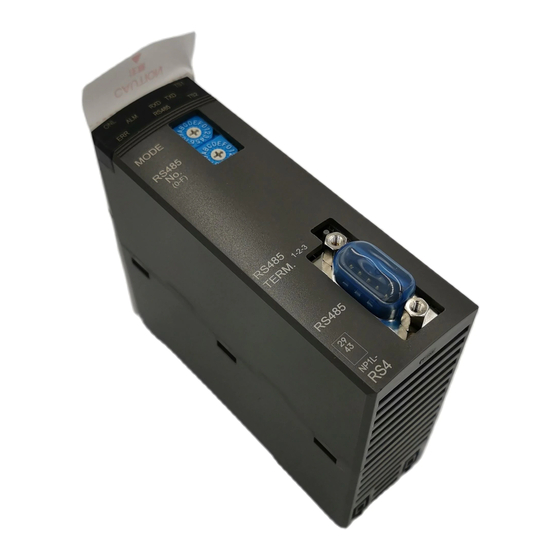
Names and functions 2-3 Names and Functions (3) NP1L-RS4 1) Status indication LED 2) Mode selection switch 3) RS-485 station No. selection switch RXD TXD RS485 MODE RS485 Nameplate (0-F) 5) RS-485 terminating resistor ON-OFF switch 6) RS-485 port (D-sub, 9-pin, male) RS485 TERM. -
Page 19: Functions
Functions 2-3 Names and Functions 2) Mode selection switch This switch is used to select a connectable device, the signal conversion and the self-diagnosis for the RS-232C port and the RS-485 port. Mode Switch Remarks RS-232C <=> RS-485 MODE RS-232C port RS-485 port Signal conversion General purpose device General purpose device Not available... - Page 20 Functions 2-3 Names and Functions 4) RS-232C port This port is D-sub, 9-pin connector (female). This connector is connected to D-sub, 9-pin connector (male). < i r r < > = > = < > = M2.6 < Screw < l l a 5) RS-485 terminating resistor ON/OFF switch This switch used to select the ON/OFF of the RS-485 terminating resistor.
-
Page 21: Dimensions
Dimensions 2-4 Dimensions Dimensions are same for NP1L-RS1,NP1L-RS2 and NP1L-RS4. (90) (37) ( N o t e ) Note: Front formation depends on each type. -
Page 22: Section 3 System Configuration
Section 3 System Configuration Page 3-1 Mounting Restrictions ....................3-1 3-1-1 Mounting position ........................3-1 3-1-2 Number of mountable modules ..................... 3-1 3-2 System Configurations ....................3-2 3-2-1 1:1 Connection using RS-232C port ..................3-2 3-2-2 1:N Connection using RS-485 port (N = max. 31 modules) ..........3-3 3-2-3 Connecting independently to RS-232C and RS-485 ports ........... -
Page 23: Mounting Restrictions
Mounting restrictions Section 3 System Configuration 3-1 Mounting Restrictions 3-1-1 Mounting position NP1L-RS1/2/4 is a general purpose communication module which is connected to the SX bus of MICREX-SX series. The mounting position on the base board is restricted as follows: They can be mounted in any slot except those for the power supply module (the two slots from the left on the base board). -
Page 24: System Configurations
1: 1 connection 3-2 System Configurations 3-2-1 1:1 Connection using RS-232C port This configuration connects to an external device having an RS-232C interface via the RS-232C port. The mode selection switch is set to “0” (zero). RS1 or RS4 <Mode selection switch: “0”> RS-232C port General purpose device RS-485 port... -
Page 25: 1:N Connection Using Rs-485 Port (N = Max. 31 Modules)
1: N connection 3-2 System Configurations 3-2-2 1:N Connection using RS-485 port (N = max. 31 modules) This configuration connects to external devices having an RS-485 interface via the RS-485 port. The mode selection switch is set to “0.” A maximum of 31 external devices can be connected. However, when all external devices are RS1 or RS4, the maximum number is limited to 15 because only 0 to F are available for addressing. -
Page 26: Connecting Independently To Rs-232C And Rs-485 Ports
1: 1 / 1: N connection 3-2 System Configurations 3-2-3 Connecting independently to RS-232C and RS-485 ports This configuration connects to external devices using the RS-232C port and RS-485 port. In this case, communication through these ports is performed independently. <Mode selection switch: “0”>... -
Page 27: Connection Using Rs-232C And Rs-485 Ports (2)
1: 1 / 1: N connection 3-2 System Configurations 3-2-4 Connection using RS-232C and RS-485 ports (2) This configuration connects to external devices using the RS-232C port and RS-485 port. <Mode selection switch: “0”> RS-232C port General purpose device RS-485 port General purpose device Power Signal conversion... - Page 28 1: 1 / 1: N connection 3-2 System Configurations <2) Communication between external device A and the CPU module> Power supply RS-485 External device External device External device RS-232C External device A (personal computer, etc.) Note: A user program for (Note) controlling external device A is necessary.
-
Page 29: Connecting A Personal Computer Loader To The Rs-232C Port And Rs-485 Port
1: 1 / 1: N connection 3-2 System Configurations 3-2-5 Connecting a personal computer loader to the RS-232C port and RS-485 port This configuration connects a D300win personal computer loader to each of RS-232C and RS-485 ports. <Mode selection switch: “3”> RS-232C port Loader RS-485 port... -
Page 30: Loader Network Configuration Using Modems (1)
Modem connecting 3-2 System Configurations 3-2-7 Loader network configuration using modems (1) This configuration enables remote programming using the public circuit by connecting a modem to the RS-232C port. RS1 or RS2 When the NP1L-RS1 is used and the mode selection switch is set to 6, A, or C, Power general purpose devices can be... -
Page 31: Loader Connecting Cable
Loader connecting 3-3 Loader Connecting Cable To connect a D300win personal computer loader to the RS-232C or RS-485 port of the general purpose communication module, the cable must be connected in the following manner. 3-3-1 When connecting to RS-232C port Because the RS-232C connector of the general purpose communication module is “female,”... -
Page 32: Self-Diagnosis
Self-diagnosis 3-4 Self-diagnosis 3-4-1 Self-diagnosis mode 1 Setting the mode selection switch of the module to “7” activates Self-diagnosis Mode “1.” This mode is used to check the internal memory and the lighting condition of LEDs. <Diagnosis flow> Start Set the mode selection switch to “7.” Check the internal memory of general purpose communication... -
Page 33: Self-Diagnosis Mode 2
Self-diagnosis 3-4 Self-diagnosis 3-4-2 Self-diagnosis mode 2 This mode is used to check the completeness of communications by looping back sent data and control signals via the communication port. (1) RS to CS signal check In this check, the general purpose communication module turns RS signal ON to check whether CS signal is looped back and turns ON, and then checks that this signal turns OFF. -
Page 34: Section 4 Software Interface
Section 4 Software Interface Page 4-1 General ......................... 4-1 4-2 Specifications for Non-procedural FB ..............4-3 4-2-1 Communication specification ....................4-3 4-2-2 FB format ..........................4-4 4-2-3 FB terminals .......................... 4-5 4-3 Initialization ......................... 4-7 4-3-1 Initialization parameters ......................4-7 4-3-2 Initialization procedure ...................... -
Page 35: General
Section 4 Software Interface 4-1 General The non-procedural FB supplied with the D300wind is used for communication between the NP1L-RS1/2/4 and external devices. The non-procedural FB performs data communication between the CPU module and external devices based on the start-stop synchronous transmission protocol. The following seven types of non-procedural FBs are offered. -
Page 36: General
4-1 General <FB operating conditions> System configuration: One FB is necessary for each external device which is connected by RS-232C or RS-485 to one general purpose communication module. However, when RS-232C/RS-485 signal conversion is enabled (the mode selection switch is set to 4) for the general purpose communication module, each FB is used by two channels. -
Page 37: Specifications For Non-Procedural Fb
4-2 Specifications for Non-procedural FB 4-2-1 Communication specification s t i s t i y t i s t i s t i y t i t i s Note: Transmission rates 300, 600, 76800, and 115200 bps can be used in the following combinations: - t l - t l... -
Page 38: Fb Format
4-2 Specifications for Non-procedural FB 4-2-2 FB format Input terminal name Output terminal name _C_free (Note 1) Open Communication ready (BOOL) OPEN (BOOL) OK Send request Open status (BOOL) S_REQ (WORD) O_STS Send data length Send end (INT) S_LEN (BOOL) S_END Send error (BOOL) S_ERR Send status... -
Page 39: Fb Terminals
4-2 Specifications for Non-procedural FB 4-2-3 FB terminals <Terminal list> c " " s z i l l b i c " " y " " y c i l z i l z i l y l l z i l c t i s l i "... - Page 40 4-2 Specifications for Non-procedural FB <Receive data R_DAT(WORD array)> Upper order Lower order <Variable declaration example(_C_free)> R_DAT [0] Data 1 Data 2 R_DAT [1] Data 3 Data 4 R_DAT:_C_RCV_TYP11; END_VAR R_DAT [31] Data 64 Data63 Up to here is assigned to _Cfr32. <Data type list>...
-
Page 41: Initialization
4-3 Initialization 4-3-1 Initialization parameters In order to initialize each individual port of the general purpose communication module, it is necessary to set values which match the communication specifications of the object external device to the individual communication parameters. The table below shows the setting contents of these parameters. - Page 42 4-3 Initialization Item Description Designates the number of receive data bytes when "Fixed length" is selected for Number of receive data bytes frame detection. When "Variable length" is selected, set this item to "0." Designates the number of start code bytes when "Variable length" is selected. Number of start code bytes "0"...
- Page 43 4-3 Initialization Item Description Calculation method to check for transmission error. D1 D2 0: Add D1 + D2 + ... + Dn 1: Add and invert BCC calculation formula Inversion of (D1 + D2 + ... + Dn) 2: EOR D1 EOR D2 EOR ...
-
Page 44: Initialization Procedure
4-3 Initialization 4-3-2 Initialization procedure When the OPEN terminal of FB is turned ON, communication parameters are transferred to the general purpose communication module, which executes processing for initialization. If initialization is impossible due to a communication parameter setting error or hardware error, FB outputs the corresponding error code (word type) to the OPEN Status (O_STS). -
Page 45: Data Sending
4-4 Data Sending 4-4-1 Data sending procedure Set data. Send data (S_DAT) Set data length. Send data length (S_LEN) Turned ON by the application program. Turned OFF by the application program. Send request (S_REQ) Processing for sending Send end (S_END) S_END and S_ERR are output in one pulse. -
Page 46: Send Status List
4-4 Data Sending 4-4-2 Send status list y l l f i c 4-12... -
Page 47: Data Receiving
4-5 Data Receiving 4-5-1 Data receiving procedure Communication ready Continuous receiving operation Receive data (R_DAT) Receive data length (R_LEN) Receive status (R_STS) Receive end (R_END) R_END In case of receive error Receive error (E_ERR) While the communication ready flag is turned ON, whether the data to be received exists or not is checked continuously and, when it exists, the operation for receiving is executed. -
Page 48: Receiving Status List
4-5 Data Receiving 4-5-2 Receiving status list y l l y t i Note: Receiving conditions The processing for receiving differs with the setting of parameter “Frame detection.” None: Receiving completes when data is received. Fixed length: Receiving completes when receive data reaches the specified number of receive data bytes. Variable length: Receiving completes when the data in a range between start and end codes is received. -
Page 49: Ras Information
4-6 RAS Information Operating status of FB is stored in the RAS infomation area. <Variable declaration example of RAS (_C_free)> RAS: _C_work_TYPE11; END_VAR < Data type list > <RAS information area (INT array)> > - - > - - 4-15... - Page 50 4-6 RAS Information • Port status Control data Error data 15 14 13 12 11 10 9 8 7 6 5 4 3 2 1 0 RS signal CS signal Have a meaning when RS-232C port is used. DR signal Reserved when RS-485 port is used.
-
Page 51: Section 5 Programming
Section 5 Programming Page 5-1 Communication Program Creating Procedure ............5-1 5-2 Installation Procedure of Standard Extended FB ............ 5-2 5-3 Registration in Library ....................5-5 5-4 Pasting Non-procedural FB ..................5-6 5-5 Communication Parameters Setting ................. 5-7 5-6 Writing the Send Data ....................5-8 5-7 Connecting Variables and Commands to FB Terminals .......... -
Page 52: Communication Program
Section 5 Programming 5-1 Communication Program Creating Procedure Taking non-procedural FB (_C_free) for example, the procedure for creating a communication program is explained below: 1) Install the standard expansion FB. Refer to “5-2 Installation Procedure of Standard Extended FB.” 2) Register the library in the project tree. Refer to “5-3 Registration in Library.”... -
Page 53: Installation Procedure Of Standard Extended Fb
Installation 5-2 Installation Procedure of Standard Extended FB The standard extended FB is included in the Programming Support Tool D300win System Software Package (CD-ROM). < Operating Procedure > (1) Activate Windows and then insert the product CD-ROM into the CD-ROM drive. The following dialog appears. Note: If the installation dialog box does not appear, perform the following operations. - Page 54 Installation 5-2 Installation Procedure of Standard Extended FB (3) When you click the [Next>] button in the [Welcome] dialog box, the [Choose Destination Locarion] dialog box appears. The target folder appears here. To change the target folder, click the [Browse...] button. The following [Choose Directory] dialog box appears. Specify a folder and then click the [OK] button.
- Page 55 Installation 5-2 Installation Procedure of Standard Extended FB (5) When installation is completed, the following [Setup Complete] dialog box appears. Click the [OK] button to complete the installation procedure. When you check here and then click the [OK] button, the product information of the standard extended FB appears.
-
Page 56: Registration In Library
Library registration 5-3 Registration in Library Individual communication FBs included in the standard expansion FB package can be used when registered in a library under a created project. (1) Left-click the [Libraries], a subtree in the “Project” tree, and then on the [Insert...] button. Then the [Include library] dialog box will appear on the screen. -
Page 57: Pasting Non-Procedural Fb
5-4 Pasting Non-procedural FB The following procedure pastes non-procedural FB “_C_free” on the LADDER code worksheet. <Pasting procedure> 1) Open the code work sheet on which you want to paste “_C_free.” Code work sheet Double-click this Left-click the desired point on the item with the left code work sheet to determine the button. -
Page 58: Communication Parameters Setting
Communication Parameters 5-5 Communication Parameters Setting Setting Parameter values are assigned to the variables (INT type array data) which are connected to the communication parameter terminal “PARA” of non-procedural FB. In this paragraph, how to do this using ST language is described. <Sample variable declaration>... -
Page 59: Writing The Send Data
Writing the Send Data 5-6 Writing the Send Data Send data is written in the variables (WORD type array data) which are connected to send data terminal “S_DAT.” When the volume of send data is small, the send data writing program is created on the same work sheet as that for expansion FB;... -
Page 60: Connecting Variables And Commands To Fb Terminals
Connecting to FB terminals 5-7 Connecting Variables and Commands to FB Terminals This paragraph describes how to program for each expansion FB terminal. _C_free BOOL BOOL OPEN BOOL WORD S_REQ O_STS BOOL S_LEN S_END BOOL S_ERR WORD S_STS BOOL R_END BOOL R_ERR WORD... -
Page 61: Operation For Sending Data
Connecting to FB terminals 5-7 Connecting Variables and Commands to FB Terminals 5-7-3 Operation for sending data Send request is made after send data and its byte length are set. Send condition After confirming that the data has been written, send request is turned ON. OK_F OPEN OK_F... -
Page 62: Section 6 Wiring
Section 6 Wiring Page 6-1 Precautions ......................... 6-1 6-2 Wiring Method ......................6-2 6-2-1 When RS-485 is used (2-wire) ....................6-2 6-2-2 When RS-485 is used (4-wire system) .................. 6-2 6-2-3 When RS-232C is used ......................6-3... -
Page 63: Precautions
Section 6 Wiring 6-1 Precautions (1) Before removing the connector, remove the fixing screws. (2) Communications cables must be isolated from high-voltage cables and power cables as far as possible. Communication cables must not be run parallel with those cables. (3) These cables should be installed as shown in the following figure. -
Page 64: Wiring Method
6-2 Wiring Method 6-2-1 When RS-485 is used (2-wire) To make a 2-wire system, as shown in the figure below, 4) and 9) as well as 3) and 8) are short-circuited in the connector, and 1) (SDB), 2) (SDA) and 5) (SG) are used to connect to external devices. External device General purpose communication module Pin No. -
Page 65: When Rs-232C Is Used
6-2 Wiring Method 6-2-3 When RS-232C is used External device General purpose communication module Pin No. Receive data Send data Communication ready (Note) Send request Connect as necessary on the external Signal ground device side. Data set ready Data channel Carrier detection Call indication Data terminal ready... -
Page 66: Section 7 Ras
Section 7 RAS Page 7-1 RAS Information of General Purpose Communication Module ......7-1... -
Page 67: Ras Information Of General Purpose Communication Module
Section 7 RAS 7-1 RAS Information of General Purpose Communication Module The following describes the procedure for monitoring and analyzing the RAS information of the general purpose communication module using the D300win. < Example system configuration > General purpose communication module MICREX-SX To external device SX bus station No.3... - Page 68 7-1 RAS Information of General Purpose Communication Module When you left-click here, the detailed RAS information of the selected module appears. Select the general purpose communication module (SX station No.3) and then left-click the [Detail RAS...] button. (3) The following [Detail RAS] dialog box of the general purpose communication module appears. First, the “Module intensive status information”...
- Page 69 7-1 RAS Information of General Purpose Communication Module (5) When you select [General purpose communication module RS1 detail RAS], the detailed RAS information appears in Contents, as shown below. No.1 No.2 No.7 0000 : 1000 9000 0000 0000 0000 0000 0000 0000 No.15...
- Page 70 7-1 RAS Information of General Purpose Communication Module • RS-232C/RS-485 Port status Control data Error data 15 14 13 12 11 10 9 8 7 6 5 4 3 2 1 0 RS signal CS signal Meaningful when the RS-232C port is used. DR signal Reserved when the RS-485 port is used.
-
Page 71: Appendix 1 Jis Code
Appendix 1 JIS Code Page JIS 7-bit Codes ....................... App.1-1 JIS 8-bit Codes ....................... App.1-1... -
Page 72: Jis 7-Bit Codes
Codes Appendix 1 JIS Code The following table shows the character-code in Japan Industrial Standards (JIS). JIS 7-bit Codes " & < ¥ > JIS 8-bit Codes Unlike 7-bit codes, JIS 8-bit codes assign different codes for alphabetic characters than for katakana characters. (The table below shows the codes for alphabetic characters.) "... -
Page 73: Appendix 2 Data Access By Command
Appendix 2 Data Access by Command Page Appendix 2-1 Command Overview ................App.2-1 Appendix 2-2 Send Data Format of Commands ............App.2-2 Appendix 2-3 Loader Command Details ..............App.2-4 Appendix 2-3-1 Read data ...................... App.2-4 Appendix 2-3-2 Write data ....................... App.2-6 Appendix 2-3-3 Batch Start of CPUs .................. -
Page 74: Appendix 2-1 Command Overview
Appendix 2 Data Access by Command Appendix 2-1 Command Overview When accessing data inside the MICREX-SX series CPU module from a personal computer or other intelligent devices, data read and write operations are possible by issuing request commands from the personal computer, without preparing send and receive application programs in the CPU module. -
Page 75: Appendix 2-2 Send Data Format Of Commands
Appendix 2-2 Send Data Format of Commands The send data of request and response commands consist of the “transmission header”, “loader command”, and “checksum code”. The format of a request command is the same as that of response command. All data are transmitted as HEX code (Not ASCII code). START code (5Ah fixed) Transmission header Data counter (L) - Page 76 Appendix 2-2 Send Data Format of Commands < Status list > y l l e l i c t i c i f z i l z i l c i f d i l f i c f i c f i c c i f f i c...
-
Page 77: Appendix 2-3 Loader Command Details
Appendix 2-3 Loader Command Details Appendix 2-3-1 Read data 1) Function This command reads the specified number of words from the specified address of the specified data memory. If the requested number of words exceeds the range of the specified memory, up to the end of the specified memory is read. 2) Command/mode code Command: 00h, Mode: 00h 3) Data format of request command/response command... - Page 78 Appendix 2-3 Loader Command Details < Memory type code > The memory type code for each memory of the MICREX-SX module is shown below. n i l n i l Note 1: When accessing the broadcast area of the PE link module by means of a command, the address does not start with 0.
-
Page 79: Appendix 2-3-2 Write Data
Appendix 2-3 Loader Command Details Appendix 2-3-2 Write data 1) Function This command writes the specified number of words to the specified address of the specified data memory. 2) Command/mode code Command: 01h, Mode: 00h 3) Data format of request command/response command Data format of request command Data format of response command Memory type... -
Page 80: Appendix 2-3-3 Batch Start Of Cpus
Appendix 2-3 Loader Command Details Appendix 2-3-3 Batch Start of CPUs 1) Function This command activates all the CPUs in the configuration at one time. Each CPU cold-starts or warm-starts depending on the condition. CPUs already activated or CPUs with the key switch set to the “RUN”... -
Page 81: Appendix 2-3-6 Batch Reset Of Cpus
Appendix 2-3 Loader Command Details Appendix 2-3-6 Batch Reset of CPUs 1) Function This command Resets all the CPUs in the configuration at one time. This command is executed regardless of the key switch position of the CPU. 2) Command/mode code Command: 04h, Mode: 03h 3) Data format of request command/response command None... -
Page 82: Appendix 2-3-9 Individual Stop Of Cpu
Appendix 2-3 Loader Command Details Appendix 2-3-9 Individual Stop of CPU 1) Function This command deactivates a specified CPU in the configuration separately. If the specified CPU has already been deactivated or the key switch is set to the RUN/STOP position, an error result. CPU specification is made with the connection mode and connection ID. -
Page 83: Appendix 3 Additional Explanation For Np1L-Rs3
Appendix 3 Additional Explanation for NP1L-RS3 Page Appendix 3-1 Applicable Version for NP1L-RS3 ............. App.3-1 Appendix 3-2 General Specifications ..............App.3-1 Appendix 3-3 Names and Functions ............... App.3-1 Appendix 3-3-1 Names ......................App.3-1 Appendix 3-3-2 Functions ....................... App.3-2 Appendix 3-4 Self-diagnosis ..................App.3-3 Appendix 3-4-1 Self-diagnosis mode 1 .................. -
Page 84: Appendix 3-1 Applicable Version For Np1L-Rs3
Appendix 3 Additional Explanation for NP1L-RS3 Communication module (Type: NP1L-RS3) has two RS-232C port. Function is almost same as other modules (Type: NP1L-RS1/RS2/RS4). Here explains difference between NP1L-RS3 and other modules (NP1L-RS1/RS2/RS4). As for common function with other modules, please read main chapter of this manual. Appendix 3-1 Applicable Version for NP1L-RS3 (Related page: p1-4) If you use NP1L-RS3, you need to use with above mentioned version CPU and Loader. -
Page 85: Appendix 3-3-2 Functions
Appendix 3 Additional Explanation for NP1L-RS3 Appendix 3-3-2 Functions 1) Status indication LED Here explains difference for NP1L-RS3. 2) Mode selection switch Mode Switch Remarks General purpose device General purpose device Programming loader General purpose device General purpose device Programming loader Programming loader Programming loader Not used... -
Page 86: Appendix 3-4 Self-Diagnosis
Appendix 3 Additional Explanation for NP1L-RS3 Appendix 3-4 Self-diagnosis (Related page: p3-10 to p3-11) Appendix 3-4-1 Self-diagnosis mode 1 Function of self-diagnosis is same as NP1L-RS1/2/4. However, LED name is different. (1) LED lighting check Of the external LEDs of the module, the lighting condition of those operated by general purpose communication module are checked. -
Page 87: Appendix 3-6 Detailed Ras
Appendix 3 Additional explanation for NP1L-RS3 Appendix 3-6 Detailed RAS (Related page: p7-3) No. 4 and No. 5 information newly added to detailed RAS information. (To NP1L-RS3 module. Currently, NP1L-RS1/RS2/RS4 doesn’t support this information.) Status of general purpose communication module Status of CH1 Status of CH2 Not used... -
Page 88: Appendix 4 Additional Explanation For Np1L-Rs5
Appendix 4 Additional Explanation for NP1L-RS5 Page Appendix 4-1 Applicable Version for NP1L-RS5 ............. App.4-1 Appendix 4-2 General Specifications ..............App.4-1 Appendix 4-3 Names and Functions ............... App.4-1 Appendix 4-3-1 Names ......................App.4-1 Appendix 4-3-2 Functions ....................... App.4-2 Appendix 4-4 Self-diagnosis ..................App.4-4 Appendix 4-4-1 Self-diagnosis mode 1 .................. -
Page 89: Appendix 4-3-1 Names
Appendix 4 Additional Explanation Appendix 4 Additional Explanation for NP1L-RS5 for NP1L-RS5 Communication module (Type: NP1L-RS5) has two RS-485 port. Function is almost same as other modules (Type: NP1L- RS1/RS2/RS4). Here explains difference between NP1L-RS5 and other modules (NP1L-RS1/RS2/RS4). As for common function with other modules, please read main chapter of this manual. Appendix 4-1 Applicable Version for NP1L-RS5 (Related page: p1-4) If you use NP1L-RS5, you need to use with above mentioned version CPU and Loader. -
Page 90: Appendix 4-3-2 Functions
Appendix 4 Additional Explanation for NP1L-RS5 Appendix 4-3-2 Functions 1) Status indication LED Here explains difference for NP1L-RS5. n i l 2) Mode selection switch Mode Switch Remarks General purpose device General purpose device Programming loader General purpose device General purpose device Programming loader Programming loader Programming loader... - Page 91 Appendix 4 Additional Explanation for NP1L-RS5 3) RS-485 station No. switch Used to set RS-485 station No. for CH1, CH2 individually. Range: 00 to 1F (HEX) The second digit is set by dip switch. OFF: 0 ON: 1 The first digit is set by rotary switch. (0 to F) 4) Terminating resistor ON/OFF switch This switch used to select the ON/OFF of the RS-485 terminating resistor.
-
Page 92: Appendix 4-4 Self-Diagnosis
Appendix 4 Additional Explanation for NP1L-RS5 Appendix 4-4 Self-diagnosis (Related page: p3-10 to p3-11) Appendix 4-4-1 Self-diagnosis mode 1 Function of self-diagnosis is same as NP1L-RS1/2/4. However, LED name is different. (1) LED lighting check Of the external LEDs of the module, the lighting condition of those operated by general purpose communication module are checked. -
Page 93: Appendix 4-7 Detailed Ras
Appendix 4 Additional Explanation for NP1L-RS5 Appendix 4-7 Detailed RAS (Related page: p7-3) RS-485 station No. switch setting appears on bit 5 to 9, 0 to 4 on communication status area. F E D C B A 9 8 7 6 5 4 3 2 1 0 Mode switch (x 8) Mode switch (x 4) Mode switch (x 2) - Page 94 Mitsui Sumitomo Bank Ningyo-cho Bldg., 5-7, Nihonbashi Odemma-cho, Chuo-ku, Tokyo 103-0011, Japan Phone: +81-3-5847-8011 Fax: +81-3-5847-8172 http://www.fujielectric.co.jp/fcs/eng/ Information in this manual is subject to change without notice.
Need help?
Do you have a question about the MICREX-SX SPH Series and is the answer not in the manual?
Questions and answers