Westermo SDW-500 Series User Manual
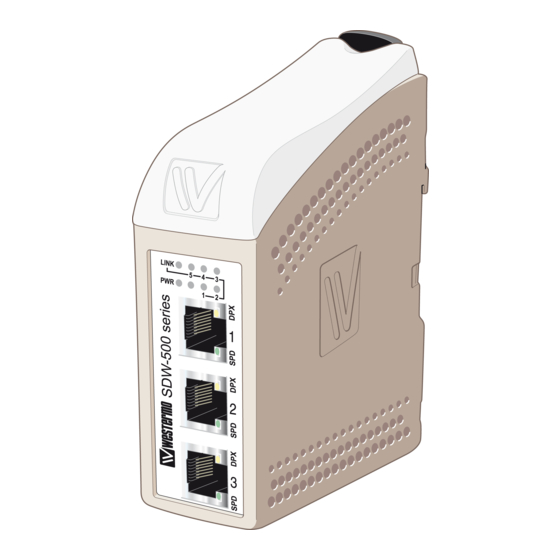
Industrial ethernet 5-port switch
Hide thumbs
Also See for SDW-500 Series:
- User manual (16 pages) ,
- User manual (21 pages) ,
- User manual (23 pages)

Subscribe to Our Youtube Channel
Related Manuals for Westermo SDW-500 Series


Summary of Contents for Westermo SDW-500 Series
- Page 1 User Guide 6644-2214 SDW-500 Industrial Ethernet 5-port Switch www.westermo.com...
-
Page 2: Legal Information
Under no circumstances shall Westermo be responsible for any loss of data or income or any special, incidental, and consequential or indirect damages howsoever caused. -
Page 3: Before Installation
Do not use or store the unit in dusty, dirty areas, connectors as well as other mechanical part may be damaged. If the unit is not working properly, contact the place of purchase, nearest Westermo dis- tributor office or Westermo Tech support. - Page 4 ATEX Information (Applicable for SDW-500 Ex series only) General This unit is intended for use in Zone 2 hazardous location only. Marking II 3 G Ex nA IIC 140°C (T3) Gc SPECIAL CONDITION WARNING – DO NOT SEPARATE WHEN ENERGIZED Indicate that this unit complies with relevant European standards that are harmonised with the 94/9/EC Directive (ATEX).
- Page 5 Ratings and safety control drawing SDW-541EX-MM-LC2 SDW-541EX-MM-SC2 Ratings \ Model SDW-550EX SDW-541EX-SM-SC15 SDW-541EX-MM-ST2 SDW-541EX-SM-LC40 SDW-541EX-SM-LC15 Power (12 – 48) VDC; 320 mA (12 – 48) VDC; 350 mA (12 – 48) VDC; 450 mA –25ºC ≤ Ta ≤ +70ºC –25ºC ≤ Ta ≤ +65ºC Ambient temperature Maximum surface 140ºC (temperatur class T3)
-
Page 6: Special Condition For Safe Use
SPECIAL CONDITION FOR SAFE USE Ambient temperature: This unit is designed for use in extreme ambient temperature conditions according to the following: SDW-550: –25ºC ≤ Ta ≤ +70ºC SDW-541: –25ºC ≤ Ta ≤ +65ºC SDW-532: –25ºC ≤ Ta ≤ +60ºC Installation in an apparatus cabinet: This unit requires installation in an Ex certified apparatus cabinet suitable for the area of use and providing a degree of protection of at least IP54. -
Page 7: Cleaning Of The Optical Connectors
Note. Fibre Optic Handling Fibre optic equipment needs special treatment. It is very sensitive to dust and dirt. If the fibre will be disconnected from the modem the protective hood on the transmitter/ receiver must be connected. The protective hood must be kept on during transportation. The fibre optic cable must also be handle the same way. -
Page 8: Declaration Of Conformity
Declaration of Conformity Westermo Teleindustri AB Declaration of conformity The manufacturer Westermo Teleindustri AB SE-640 40 Stora Sundby, Sweden Herewith declares that the product(s) Type of product Model Art no Industrial Ethernet switch SDW-500 series 3644-0001, -0005, -0015, -0019, -0020,-0021, -... -
Page 9: Environmental Conditions
Environmental conditions Isolation between interfaces Power Interface to all other 2.8 kV DC 2.0 kV RMS @ 50 Hz and 60 s duration TX signal Interface to all other 2.1 kV DC 1.5 kV RMS @ 50 Hz and 60 s duration TX shield Interface to all other 1.5 kV DC 1.0 kV RMS @ 50 Hz and 60 s duration Environmental... - Page 10 1. Description The SDW-550 is an Industrial Ethernet 5-port switch. All ports support auto-negotiation, but DIP-switches also allow speed and duplex configuration of any individual TX port. It is also possible to set up one port to monitor traffic to/from the switch. The SDW-550 has been designed to meet high industrial specifications, providing very high dependability in harsh environmental conditions.
-
Page 11: Interface Specifications
Interface specifications Power SDW-500 series Rated voltage 12 –48 VDC, polarity protected Operating voltage 9.6 – 57.6 VDC Rated current @12 VDC power input SDW-550 320 mA SDW-541-MM-SC2 450 mA SDW-541-MM-ST2 450 mA SDW-541-SM-LC15 450 mA SDW-541-SM-SC15 350 mA SDW-541-SM-LC40... - Page 12 Connections LED indicators Network RJ-45 connection Network Fibre connection or RJ-45 connection Power connection Available models: … SDW-550 10/100Base-T/TX: 5 ports … SDW-541 10/100Base-T/TX: 4 ports 100Base-FX: 1 port … SDW-532 10/100Base-T/TX: 3 ports 100Base-FX: 2 ports NOTE! SDW-532-MM-SC2-SM-SC15 Port 4: SC Single mode 15 km connector Port 5: SC Multi mode 2 km connector 6644-2214...
- Page 13 Power The SDW-500 series supports redundant power connection. The positive input are +VA and +VB, the negative input for both supplies are COM. 3-pos screw terminal Description Power The power is drawn from the input with the highest A: 9.6 – 57.6 VDC voltage.
-
Page 14: Led Indicators
LED indicators At power on the PWR flashes during initialising. Indicators (LED) Power (PWR) Link (LINK) of every port Speed (SPD) and duplex (DPX) of TX ports Status Indication of Internal power, initialising OK Slow flash Initialisation progressing Fast flash Initialisation error LINK No Ethernet link... - Page 15 DIP switch settings SDW-550 DIP-switches are accessible under the lid on top of the unit. DIP-switches are used to configure the unit. Warning! Prevent damage to internal electronics from electrostatic discharges (ESD) by discharging your body to a grounding point (e.g. use of wrist strap), before the lid on top/front of the unit is removed.
-
Page 16: Port 1 Settings
Port 1 settings Port 3 settings Auto-negotiation and Auto-negotiation and auto MDI/MDI-X disabled auto MDI/MDI-X disabled 1 2 3 4 5 6 7 8 1 2 3 4 5 6 7 8 Auto-negotiation and Auto-negotiation and auto MDI/MDI-X enabled auto MDI/MDI-X enabled 1 2 3 4 5 6 7 8 1 2 3 4 5 6 7 8 10 Mbit/s speed selected... -
Page 17: Port Mirroring Settings
Port 5 settings Port mirroring settings Auto-negotiation and No monitoring selected auto MDI/MDI-X disabled 1 2 3 4 5 6 7 8 1 2 3 4 5 6 7 8 Auto-negotiation and Monitoring selected auto MDI/MDI-X enabled 1 2 3 4 5 6 7 8 1 2 3 4 5 6 7 8 10 Mbit/s speed selected 1 2 3 4 5 6 7 8... - Page 18 DIP switch settings SDW-541 and SDW-532 DIP-switches are accessible under the lid on top of the unit. DIP-switches are used to configure the unit. Warning! Prevent damage to internal electronics from electrostatic discharges (ESD) by discharging your body to a grounding point (e.g. use of wrist strap), before the lid on top/front of the unit is removed.
- Page 19 Port 1 settings Auto-negotiation and auto MDI/MDI-X disabled 1 2 3 4 5 6 7 8 Auto-negotiation and auto MDI/MDI-X enabled 1 2 3 4 5 6 7 8 10 Mbit/s speed selected 1 2 3 4 5 6 7 8 100 Mbit/s speed selected Port 4 settings* 1 2 3 4 5 6 7 8...
-
Page 20: Installation
Installation Mounting / Removal Before mounting or removing the unit: Prevent damage to internal electronics from electrostatic discharges (ESD) by discharging your body to a grounding point (e.g. use of wrist strap). Prevent access to hazardous voltages by disconnecting the unit from AC/DC mains supply and all other electrical connections. - Page 24 9 Chemin de Chilly 91160 CHAMPLAN Phone:+886 2 8911 1710 Tél : +33 1 69 10 21 00 • Fax : +33 1 69 10 21 01 E-mail: info@westermo.com E-mail : infos@westermo.fr Westermo Teleindustri AB have distributors in several countries, contact us for further information.
Need help?
Do you have a question about the SDW-500 Series and is the answer not in the manual?
Questions and answers