
Related Manuals for Westermo SANDCATS-2000 Series


Summary of Contents for Westermo SANDCATS-2000 Series
- Page 1 SANDCATS-2000 series Industrial Ethernet 5-port Unmanaged Switches...
-
Page 2: Table Of Contents
SandCat-2000 Series User Guide Table of Contents 1 Safety Instruction ....................4 Symbols ....................6 Safety Notes ..................6 Certification ..................7 2 Switch Overview ....................8 Introduction ..................8 2.1.1 Overview ....................8 2.1.2 Main Features ..................8 2.1.3 Switch Models ..................10 Technical Specifications ................. - Page 3 SandCat-2000 Series User Guide Package Contents .................. 21 Validating Operational Function ..............21 Installing the Switch ................22 3.5.1 Installation Requirements ............... 22 3.5.2 Installing Guidelines ................22 3.5.3 DIN Rail Mounting .................. 23 3.5.4 Removing the DIN-Rail Mounting Kit ............24 3.5.4.1 Ethernet Cable Wiring ................
-
Page 4: Safety Instruction
1. When using a fiber optic port, never look at the transmit laser while it is powered on. Also, never look directly at the fiber port and fiber cable end when they are powered on. If you need further assistance, please contact Westermo. A Warning symbol indicates a hazardous situation which, if not avoided, ✓... - Page 5 SandCat-2000 Series User Guide • Check the rated voltage and terminal array before wiring. Avoid environments over 50 ℃ of temperature. Avoid placing it directly in the sunlight. • Ensure that inputs and outputs are made according to the module specification. Wire the system using standard cables.
-
Page 6: Symbols
SandCat-2000 Series User Guide Symbols A Caution symbol indicates a potentially hazardous situation to you. A Warning symbol indicates situations that can be potentially lethal or extremely hazardous to you. An Attention symbol indicates potential damage to programs, devices, or data. Identifies information that is critical for successful application and understanding of the product. -
Page 7: Certification
SandCat-2000 Series User Guide Certification Note! For specific information relating to certification of this module type, see the separate certification document summary. The following certification information applies to SandCat-2000 series models: CE compliance ⚫ FCC part 15b compliance ⚫ UL 62368-1 ⚫... -
Page 8: Switch Overview
SandCat-2000 Series User Guide 2 Switch Overview Introduction 2.1.1 Overview The SandCat-2000 series is designed with robustness and a long service life in mind. It has an excellent set of industry approvals and certifications, ensuring its reliability and performance. The devices operate in a wide temperature range from -40 to +75 °C (-40 to +167 °F), making them suitable for harsh industrial environments. - Page 9 SandCat-2000 Series User Guide • 4 x RJ-45 ports for 10/100Base-TX Ethernet Ports and 1 x 100Base-FX (SandCat-2305-F1 series) • Industrial Slim Size Design • Broadcast storm protection • Support 802.1p QoS (CoS, DSCP) • Supports AC 1.5KV Hi-port isolation protection Only valid for Ethernet SandCat-2000 Series User Guide Page 9 of (34)
-
Page 10: Switch Models
SandCat-2000 Series User Guide 2.1.3 Switch Models The SandCat-2000 series is available in the following models: Switch Model Description Image SandCat-2305-T5-LV Industrial 5 x RJ45 10/100Base-TX Ethernet ports SandCat-2305-F1- Industrial 4 x RJ45 10/100Base-TX Ethernet ports MM-T4-LV and 1 x 100Base-FX SandCat-2305-F1- SM-T4-LV SandCat-2000 Series User Guide... -
Page 11: Technical Specifications
SandCat-2000 Series User Guide Technical Specifications Specifications Description SandCat-2305-T5-LV • 5-port 10/100BaseT(X) RJ-45Ethernet Port • Non-blocking Switching Performance • Auto negotiation speed, Full/Half duplex mode and auto MDI/MDI-X connection Enclosure Port SandCat-2305-F1-MM-T4-LV, SandCat-2305-F1-SM-T4-LV • 4-port 10/100T(X) RJ-45Ethernet Port • Non-blocking Switching Performance •... - Page 12 SandCat-2000 Series User Guide Specifications Description Packet Buffer 448 Kbits packet buffer Transfer 64 Bytes ~ 1536 Bytes packet size Transfer 14,880 pps for 10 Mbps, 148,800 pps for 100 Mbps Performance Broadcast Default enabled Storm Control Installation DIN-Rail mounting Case IP30 grade metal case Without DIN rail clip –...
-
Page 13: Front Panel
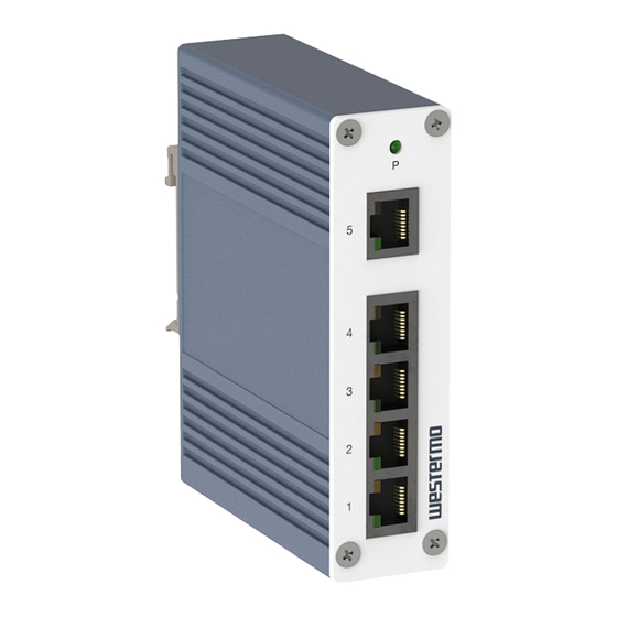
SandCat-2000 Series User Guide Front Panel Described in this section are the front panel components of the SandCat-2305 switch. 2.3.1 SandCat-2305-T5-LV The LEDs and ports for the SandCat-2305 model are located on the front panel of the switch as illustrated in the following illustrations. Figure 1: Front Panel of SandCat-2305 No. -
Page 14: Sandcat-2305-F1-Mm-T4-Lv, Sandcat-2305-F1-Sm-T4-Lv
SandCat-2000 Series User Guide 2.3.2 SandCat-2305-F1-MM-T4-LV, SandCat-2305-F1-SM-T4-LV The LEDs and ports for the SandCat-2305-F1 are located on the front panel of the switch as illustrated in the following illustrations. Figure 2: Front Panel of SandCat-2305-F1 No. Item Description Fiber LED See Front Panel LEDs on page 15 for further details System LED RJ-45 console ports... -
Page 15: Front Panel Leds
SandCat-2000 Series User Guide 2.3.3 Front Panel LEDs The system LEDs are used to monitor the switch activity and performance. The following illustration depicts the front panel on the SandCat-2000 series. A specific LED panel is dependent on a specific SandCat model. -
Page 16: Rear View
SandCat-2000 Series User Guide Rear View The following rear view illustrates the rear view of a SandCat-2000 series device. For demonstration purposes a single sample is illustrated. Varying models may differ in shape and form. Figure 4: Rear Panel of SandCat-2000 series No. -
Page 17: Bottom View
SandCat-2000 Series User Guide Bottom View The following bottom view illustrates the bottom view of a SandCat-2000 series device. The power inputs and relay connectors are located on the bottom panel of the switch as illustrated in the following illustrations. For demonstration purposes a single sample is illustrated. Varying models may differ in shape and form. -
Page 18: Dimensions
SandCat-2000 Series User Guide 2.6 Dimensions The power inputs and relay connectors are located on the rear panel of the switch as illustrated in the following illustrations. 2.6.1 SandCat-2305-T5-LV Figure 6: Dimensions of 5-Port SandCat-2305 SandCat-2000 Series User Guide Page 18 of (34) -
Page 19: Sandcat-2305-F1-Sm/Mm-T4-Lv
SandCat-2000 Series User Guide 2.6.2 SandCat-2305-F1-SM/MM-T4-LV Figure 7: Dimensions of 5-Port SandCat-2305-F1 SandCat-2000 Series User Guide Page 19 of (34) -
Page 20: Hardware Installation
SandCat-2000 Series User Guide 3 Hardware Installation Electrical Safety Information Voltage, frequency, and current requirements must be met according to the manufacturer's label. Using a power source other than those specified power rating may cause improper operation, damage to the equipment, or pose a fire hazard. This equipment contains no user-serviceable parts. -
Page 21: Package Contents
SandCat-2000 Series User Guide industrial equipment. It may be difficult to ensure electromagnetic compatibility in other environments without appropriate precautions due to conducted and radiated disturbances. This equipment is provided as open-type equipment. Enclosures must be designed appropriately to prevent personal injury resulting from access to live parts and to suit the specific environmental conditions that will be present. -
Page 22: Installing The Switch
SandCat-2000 Series User Guide Installing the Switch 3.5.1 Installation Requirements The fastest way to install the product is by choosing the DIN rail mount option. Moreover, this option efficiently utilizes the available rail space. To secure the switch, you can use the metal DIN rail kit provided. It can be attached to the back of the device, allowing for mounting on a standard DIN rail: •... -
Page 23: Din Rail Mounting
SandCat-2000 Series User Guide • Fan and blowers in cooling mechanisms can draw dust and other particles, resulting in contaminant buildup inside the chassis, resulting in system malfunction. In order to ensure the best performance of this equipment, it must be installed in a dust-free environment. 3.5.3 DIN Rail Mounting Place the rear panel of the switch in front of the DIN rail, ensuring that the top part of the DIN... -
Page 24: Removing The Din-Rail Mounting Kit
SandCat-2000 Series User Guide Figure 9: Example of an Installed DIN Rail Kit Hold the bottom of the switch and gently tilt it upward. If you encounter resistance, it indicates that the switch has been properly installed. If you do not experience any resistance, it is advisable to restart the installation process from the beginning. -
Page 25: Ethernet Cable Wiring
SandCat-2000 Series User Guide Figure 10: Removing a DIN Rail 3.5.4.1 Ethernet Cable Wiring You should use data-quality twisted-pair cabling (rated CAT5 or higher) for RJ-45 connectors. For optimal performance, shielded cabling should be used. Additional protection may be provided by shielded cabling. - Page 26 SandCat-2000 Series User Guide Figure 11: Mounting a Switch in a Rack Note! Ethernet cables use pins 1, 2, 3, and 6 of an 8-pin RJ-45 connector. The signals of these pins are converted by the automatic MDI-X function, as shown in the table below: Ethernet Cable Pin Definition Pin MDI-X Signals...
-
Page 27: Connecting Power Inputs
AC mains by double or reinforced insulation when unit with DC power. If need further assistance, please contact Westermo for further information. Furthermore, the chassis ground screw terminal should be connected to the chassis ground or earth in the field site. Insert the Earth Ground Screw with the green-yellow wire (wire size: 16 AWG minimum), and tighten the screw. -
Page 28: Considerations
SandCat-2000 Series User Guide Figure 12: Power Wiring Diagram 3.5.5.2 Considerations Before wiring the device, consider the following guidelines: • For better management and servicing, label all wiring and cabling to the various devices. • Earthing conductors must have at least 1.5 mm2 cross section. •... - Page 29 SandCat-2000 Series User Guide The ground connection must always be made first and disconnected last when installing or replacing the unit. Make sure the device is properly grounded before connecting power or Ethernet cables to it. An improper grounding setup may cause a safety risk and could be hazardous.
-
Page 30: Wiring A Relay
SandCat-2000 Series User Guide 3.5.6 Wiring a Relay The two contacts on the side and the front two contacts on the 2-contact terminal block connector are for the AC/DC inputs. As illustrated in the following figure, the side and front view of a terminal block are displayed. - Page 31 SandCat-2000 Series User Guide To service or wire the switch, it is essential to power down the device and disconnect the power cord. To wire the power inputs: Ensure that the power is disconnected from both the switch and the power converter before proceeding.
- Page 32 SandCat-2000 Series User Guide Figure 14: Installing Power Cabling in a Terminal Block Ensure the terminal block is secure by pressing it firmly in the receptor. If necessary, tighten the screws on the terminal block. If there is no visible gap between the terminal block and the receptor, it indicates that the terminal block is correctly seated.
-
Page 33: Disconnecting Power Inputs
SandCat-2000 Series User Guide 3.5.6.2 Disconnecting Power Inputs Prior to disconnecting any modules or cables, ensure that the power is switched off. It is important to note that the device only supports the voltage specified on the label. Do not use any power components not explicitly designated for the switch device. - Page 34 SandCat-2000 Series User Guide DOCUMENT CHANGE SUMMARY SandCat-2000 Series User Guide Page 34 of (34)
- Page 35 Westermo • Metallverksgatan 6, SE-721 30 Västerås, Sweden Tel +46 16 42 80 00 Fax +46 16 42 80 01 E-mail: info@westermo.com www.westermo.com REV. A 6630-2200 2024-01 Westermo Network Technologies AB, Sweden...
Need help?
Do you have a question about the SANDCATS-2000 Series and is the answer not in the manual?
Questions and answers