Advertisement
Advertisement
Table of Contents

Related Manuals for Extreme Flight PEREGRINE


Summary of Contents for Extreme Flight PEREGRINE
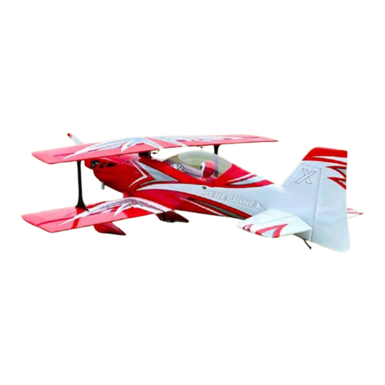
- Page 1 70CC Aerobatic Biplane Aerobatic Biplane Assembly Guide Assembly Guide...
- Page 2 ALL liability for the use of this product, please return it to the place of purchase immediately. Extreme Flight RC, Ltd. guarantees this kit to be free of defects in materials and workmanship for a period of 30 DAYS from the date of purchase.
- Page 3 Dimensions and Specs...
- Page 4 Scorpion Power System offers a couple of power system options depending on your desired flight performance and flight enve- lope. Their motors pair with suitable Cross Mount and Standoff Sets to be a convinient bolt on fit to the front of the Peregrine.
- Page 5 1.Unpacking and Sealing Covering Your aircraft has been on a journey around the world since it left our factory. Although the covering material was perfectly smooth when it was boxed up, changes in weather and humidity may have wrinkled the covering material. For certain, wrinkles will appear in the covering once you have unpacked your aircraft and it adjusts to the atmospheric conditions in your region.
-
Page 6: Landing Gear
2.Landing Gear The Peregrine uses a carbon-fiber high strength landing gear. The 70CC Peregrine landing gear sweeps BACK when properly installed. See photo. The landing gear installs onto the fuselage using four M4 screws and washers, which thread into pre-installed blind nuts in the fuselage. - Page 7 Install the axles onto the landing gear using the self-locking nuts, tighten with a 10mm socket or wrench. Each axle has a flat spot on the end, orient it to point DOWN, toward the runway, when the plane is upright. The wheel retainers incorporate a wheel pant support.
- Page 8 Install the wheel pant over the wheel and axle, apply loctite and start the M3 screws which retain the pant to the gear, but do not tighten. Flex the pant away from the retainer and apply some epoxy glue between the retainer and pant. By stabilizing the pant, this design lengthens the life of your wheels pants.
- Page 9 If you do so, it is NOT necessary to restrain the wire pivot, it will not fall out in flight. However, since the peregrine is not an extremely large aircraft, we do not expect very many users will want to remove the rudder.
-
Page 10: Wing Struts
4.Wing Struts The Peregrine uses a center strut, called a “cabane” strut. The cabane strut is permanently glued into the fuselage. Test fit the cabane into the fuselage as shown WITHOUT glue. The cabane sits down in the slot onto a structural floor piece in the upper fu- selage. - Page 11 In-between the wings there are struts called “interplane” (between the planes of the wings) struts. These are quick-release with steel pins which hold them in place for flight. Locate the four interplane strut mounts as shown, they are marked to indiciated which wings they mount into, upper or lower wings.
- Page 12 Lower wings: We recommend MPX 1-wire connectors to connect the wing panel to the fuselage. 2 x 12” (from MPX connector to receiver) The Peregrine has a plastic tube installed in the rear fuselage to guide the servo extensions wires. We recommend to connect the 24”...
- Page 13 Assemble the rudder pushrod by screwing the ball links onto the metal turnbuckle as shown. Note that, to make the pushrod length-adjustable after installation, one end is right-hand threaded, the opposite end is left-hand thread. Install the rudder push- rod to the rudder horn as shown. Note that the rudder pushrod and other pushrod hardware bags included both long and shorter M3 screws.
- Page 14 To make the horizontal stabs on the Peregrine easily removable, the elevator servos mount inside the stabilizers. This is common on giant scale aircraft; if this is the first time you have encoutered this style of elevator servo mount, note that the first time you assemble one it will require some patience.
- Page 15 The Peregrine uses 4 aileron servos, one in each wing panel. Start by checking the total length of your servo wires. On the upper wings, a short wire extension is required. For this build using Savox 1270 servos, a 3” extension is correct. We recommend a 3”- 6”...
-
Page 16: Gasoline Fuel System
We recommend a 24 oz. fuel tank for 70-76CC use. Normally we mount the tank into the fuselage of an airplane before attach- ing the plumbing, but in the tight confines of the Peregrine, it is easier to attach the lines first and THEN place the tank on the tray and apply velcro straps to it. - Page 17 The kit has mounting and outlets for the TD-110H included and built in, but because the peregrine fuselage is narrow and compact, the installation procedure is unique and must be followed exactly. Remove the wood cover plate in the front of the fuselage to reveal the canister muffler mount area. The 110H canister outlet tube must be shortened.
- Page 18 Place the mount into position as shown from the rear, allow it to sit, loose, against its mounting area in the fuselage. Insert the canister muffler into the fuselage from the front, twisting as necessary to feed the outlet pipe through the fuselage. As the rear of the canister moves past the mounting area, slip the mount over the canister.
-
Page 19: Engine Mounting
The cowl of the Peregrine is much larger and more complex than a typical 70CC class cowl. It is subject to a bit more dimen- sional error than smaller cowls during the molding process. We recommend, when drilling the firewall for your engine, that you drill ONLY two holes, upper left and lower right, and quickly test mount the engine and test fit the cowl and spinner to verify perfect alignment. -
Page 20: Throttle Linkage
9. Throttle Linkage The Peregrine has two alternate throttle servo locations on either side of the motor mounting box. Choose the one which best suits your engine/carburetor and glue the servo mounting plate on that side using either CA or epoxy glue. Install the servo with a 1-inch arm and install the pushrod as shown using locking nuts. - Page 21 10.In-Cowl exhaust The Peregrine can also use “stock” or “in-cowl” mufflers on its 70-76CC engine. The use of these mufflers requires cutting holes in the bottom of the cowl for exit. Your kit includes a clear plastic marking tool to assist in locating these holes accurately. Install the mufflers onto the engine and mark and cut the clear plastic tool until the holes are perfect, then place the tool over the cowl bottom and mark the cowl for cutting.
- Page 22 10.Finishing the canister exhaust After the throttle linkage is in place, you can finish the installation of the exhaust header and coupler. Frequently, there is in- terference between the Y-header and the fuel nipple/fuel line to the carburetor. The fuel inlet into the carburetor is a press-fit and can be turned for clearance.
- Page 23 11. Cowl cooling setup The Peregrine has a unique cowl setup which has direct flow-through cooling tunnels for the engine cylinder heads. It takes more time to set up than a typical cowl. The setup consists of inlet ducts which take air from the front of the cowl to each cylinder head, and exit ducts which take the air from the heads to the side outlets of the cowl.
- Page 24 OR, if you prefer, refer to the 70CC Peregrine page on the Extreme FlightRC.com website for links to 3D printing files for...
- Page 25 The Peregrine includes a battery hatch door integrated into the upper cowl half. This is for electric flight use only, it is not hardened against vibration the way a gasoline hatch door is. If your power system is gasoline, we recommend to do your maiden flight and verify that everything is proper, and then apply a bead of silicone glue or rubberized glue such as Gorilla Clear Bond to the battery hatch mounting flange and install it semi-permanently.
- Page 26 We balance with an empty fuel tank; the fuel tank on the Peregrine is very near the CG anyway, so it matters little if it’s empty or full. The Initial CG range of the Peregrine is as shown.
- Page 27 As you get used to your Peregrine, you can tailor your mixes perfectly to your individual plane. In our test, we actually preferred a curved rudder-to-aileron mix which increased from approx 5% at center to approx 10% at full rudder, but this is very subtle and you may find it not worth the effort.
- Page 28 The Peregrine uses quick-latches to attach the wings. Each set of wings uses one large and one small wing tube. Make sure all latches are attached and locked before flight.
Need help?
Do you have a question about the PEREGRINE and is the answer not in the manual?
Questions and answers