Table of Contents
Advertisement
Quick Links
Advertisement
Table of Contents

Related Manuals for Woodland Mills Woodlander XL HM136MAX


Summary of Contents for Woodland Mills Woodlander XL HM136MAX
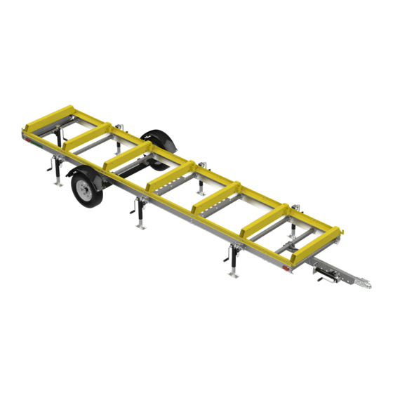
- Page 1 ™ *Track Not Included OPERATOR’S MANUAL The Woodlander ® XL is sold as an off-road only sawmill trailer compatible with HM126, HM130, HM130MAX ® , & HM136MAX ™ sawmills. Woodlander ® is a registered trademark of Woodland Mills, Inc.
- Page 2 This page intentionally left blank.
-
Page 3: Table Of Contents
HM136MAX ™ Woodlander ® XL Operator’s Manual TABLE OF CONTENTS TABLE OF CONTENTS __________________________________________________1 INTRODUCTION ________________________________________________________3 GENERAL SAFETY RULES_______________________________________________4 INSPECTION/MAINTENANCE _____________________________________________5 TECHNICAL SPECIFICATIONS ____________________________________________6 BOLT TORQUE SPECIFICATIONS _______________________________________6 UNPACKING ___________________________________________________________7 COMPONENT LISTS ____________________________________________________8 TO-SCALE HARDWARE ______________________________________________10 BOLTS & SCREWS ___________________________________________________10 WASHERS ___________________________________________________________13 NUTS _______________________________________________________________13 SAWMILL COMPONENTS_____________________________________________14... - Page 4 HM136MAX ™ Woodlander ® XL Operator’s Manual 18. NAMEPLATES ___________________________________________________54 19. HEAD LOCK-DOWN PLATES _______________________________________56 SAWHEAD CARRIAGE LOCK-DOWN POSITIONS ________________________57 20. WHEELS _______________________________________________________58 WHEEL ALIGNMENT ADJUSTMENT ____________________________________59 21. FENDERS ______________________________________________________60 22. SAFETY CHAIN __________________________________________________62 23. CANT HOOK LEVERAGE PLATES ___________________________________63 OPERATION __________________________________________________________64 LOCKING-DOWN THE SAWMILL HEAD _________________________________64 REPLACEMENT PARTS ORDERING ______________________________________66...
-
Page 5: Introduction
If you have any questions relative to a particular application, DO NOT use the trailer until you have first contacted Woodland Mills to determine if it can or should be performed using the product. -
Page 6: General Safety Rules
HM136MAX ™ Woodlander ® XL Operator’s Manual GENERAL SAFETY RULES WARNING! Read and understand all instructions. Failure to follow all instructions listed below may result serious injury. WARNING! The warnings, cautions, and instructions discussed in this instruction manual cannot cover all possible conditions or situations that could occur. -
Page 7: Inspection/Maintenance
HM136MAX ™ Woodlander ® XL Operator’s Manual INSPECTION/MAINTENANCE • Check the tires before all trips. Make sure they are inflated to the pressure shown on the tire. • Grease the axle bearings every 3 months or 1000 miles [1600 km], whichever comes first. •... -
Page 8: Technical Specifications
HM136MAX ™ Woodlander ® XL Operator’s Manual TECHNICAL SPECIFICATIONS Item Specification Trailer Axle Independent Torsion Axle Design Trailer Wheels 5 Bolts @ 4.5 in [114 mm] & 175/80R13 Approved Tires Tire Pressure Refer to Tire Wheel Nut Torque 80 ft•lb [110 N•m] Trailer Ball Coupler 2 in [50 mm] Trailer Lights LED Light Kit (stop, turn, tail, side markers, and license plate light) Finish Powder Coat Paint / Galvanized Steel... -
Page 9: Unpacking
HM136MAX ™ Woodlander ® XL Operator’s Manual UNPACKING Remove all the parts from both the steel trailer crate and trailer extension box. Set the steel trailer crate aside as it will be used as a support for several of the assembly steps. 0009012-M-EN: Rev A Page 25-Oct-2023... -
Page 10: Component Lists
HM136MAX ™ Woodlander ® XL Operator’s Manual COMPONENT LISTS Verify all component and hardware quantities are correct prior to assembling the trailer. Note: component quantities shown below are the total quantities from both the Woodlander ® Trailer and Woodlander ® Trailer Extension crates. - Page 11 HM136MAX ™ Woodlander ® XL Operator’s Manual Wiring Harness Axle Shim Plate (North America) [0001682] [0001676-1] Wheel Nameplate [175-80R13] [0004445] 13/16 Hitch Ball Tongue Coupler 1-5/8 [0001371] (North America) [0001381] Tongue Bracket Ratchet Strap [0001372] [0005146] Knob Cant Hook 13/16 M10 X 30 mm Leverage Plate [0001698]...
-
Page 12: To-Scale Hardware
HM136MAX ™ Woodlander ® XL Operator’s Manual TO-SCALE HARDWARE BOLTS & SCREWS Hardware graphics are printed at 1:1 scale for ease of identification. Simply place the hardware over the image in the tables to verify it is the correct size. Hardware quantities shown below are the total quantities from both the Woodlander ®... - Page 13 HM136MAX ™ Woodlander ® XL Operator’s Manual FHH-MBJ075FCJ M8 X 1 X 20 mm FLANGED HEX BOLT FHH-MBJ080FCJ M8 X 1 X 25 mm FLANGED HEX BOLT 172x FHH-MBM085FCM M10 X 1.5 X 30 mm FLANGED HEX BOLT FHH-MBM090PCM M10 X 1.5 X 35 mm FLANGED HEX BOLT FHH-MBM095PCM M10 X 1.5 X 40 mm FLANGED HEX BOLT FHH-MBM125PCM...
- Page 14 HM136MAX ™ Woodlander ® XL Operator’s Manual FHH-MBR090PCM M12 X 1.75 X 35 mm FLANGED HEX BOLT FHH-MBR135PCM M12 X 1.75 X 80 mm FLANGED HEX BOLT SHC-MBM175PTA M10 X 1.5 X 120 mm SOCKET HEAD CAP SCREW PPH-MBA075FCE*** M5 X 0.8 X 20 mm PHILLIPS PAN HEAD SCREW * M12 X 1.75 X 70 mm Hex Bolts not applicable on European trailers ** M12 X 1.75 X 100 mm Hex Bolts not applicable on North American trailers *** M5 X 0.8 X 20 mm Phillips Pan Head Screw quantity 12x on European trailers...
-
Page 15: Washers
HM136MAX ™ Woodlander ® XL Operator’s Manual WASHERS FTW-MBE000AJ FTW-MBM000AJ M6 FLAT WASHER M10 FLAT WASHER NUTS 0006202 HLN-MBECH M12 X 1.5 LUG NUT M6 X 1 LOCK NUT HLN-MBMCL HLN-MBRCL M10 X 1.5 LOCK NUT M12 X 1.75 LOCK NUT FLN-MBACH FLN-MBJCH M5 X 0.8 FLANGED LOCK NUT*... -
Page 16: Sawmill Components
HM136MAX ™ Woodlander ® XL Operator’s Manual SAWMILL COMPONENTS These components from the sawmill and sawmill track extension crates are required to build the trailer. They do not ship with the Woodlander ® XL trailer. T-Bolt Track Rail M10 X 40 mm [0001073] [0001059] Reinforcement... -
Page 17: Trailer Assembly
HM136MAX ™ Woodlander ® XL Operator’s Manual TRAILER ASSEMBLY 1. TOOLS REQUIRED Tool Specification Phillips Head Screwdriver No. 3 Wrench/Socket 8 mm Wrench/Socket 9 mm Wrench/Socket 10 mm Wrench/Socket 13 mm Wrench/Socket 14 mm Wrench/Socket 15 mm Wrench/Socket 18 mm Adjustable Wrench Variable Torque Wrench... -
Page 18: Track Rails, Joining Gussets, Log Bunk
HM136MAX ™ Woodlander ® XL Operator’s Manual 2. TRACK RAILS, JOINING GUSSETS, LOG BUNK Using the hardware listed below, assemble the gussets to the track as shown on the next page. Torque all bolts per the table in section BOLT TORQUE SPECIFICATIONS. M10 X 30 mm Flanged Hex Log Bunk... - Page 19 HM136MAX ™ Woodlander ® XL Operator’s Manual Using the shipping crate as an assembly aid, lay two (2) 4X4s across the top the crate near each end. Position the track/gusset assembly on the 4X4s, ensuring it is centred end-to-end. The 4X4s need to be long enough to support the track rails but shorter than the track is wide. Front Rear Use 43 in [1092 mm] long 4X4s.
- Page 20 HM136MAX ™ Woodlander ® XL Operator’s Manual Front Rear Log Bunk M10 X 30 mm bolts one end of Joining Gusset reinforcement plate 0009012-M-EN: Rev A Page 25-Oct-2023...
-
Page 21: Long Side Plates, Joining Gussets
HM136MAX ™ Woodlander ® XL Operator’s Manual 3. LONG SIDE PLATES, JOINING GUSSETS Using the hardware listed below, hang the long side plates and centre anti-tip rails on the centre track section. Snug the bolts up, but leave them loose enough to move the plates. M10 X 30 mm Long Side Flanged Hex... - Page 22 HM136MAX ™ Woodlander ® XL Operator’s Manual Anti-Tip Rail Long Side Plate Joining Gusset 0009012-M-EN: Rev A Page 25-Oct-2023...
-
Page 23: Track Rails, End Bunks, End Gussets
HM136MAX ™ Woodlander ® XL Operator’s Manual 4. TRACK RAILS, END BUNKS, END GUSSETS Using the hardware listed below, add the remaining track sections and end bunks. Leave the bolts loose. M10 X 30 mm Flanged Hex End Bunk Bolt M10 Flanged End Gusset Lock Nut... - Page 24 HM136MAX ™ Woodlander ® XL Operator’s Manual End Bunk End Gusset Track Rail Support the track using a bolt. This bolt will be removed when the short side plates are added. 0009012-M-EN: Rev A Page 25-Oct-2023...
-
Page 25: Swivel Jacks [Temporary]
HM136MAX ™ Woodlander ® XL Operator’s Manual 5. SWIVEL JACKS [TEMPORARY] Using 4 swivel jacks, place 2 under each end bunk and level the assembly while still using the crate as support in the middle. Measure diagonally to check for squareness. Snug all of the bolts, but do not fully tighten. -
Page 26: Joining Log Bunks
HM136MAX ™ Woodlander ® XL Operator’s Manual 6. JOINING LOG BUNKS Using the hardware listed below, install the log bunks to the track rails and joining gussets. Use eight (8) M10 X 40 mm bolts through each bunk. Tighten the bolts in the order instructed throughout this section. - Page 27 HM136MAX ™ Woodlander ® XL Operator’s Manual Front Note: bunks are oriented with log support sleeves towards the front M10 X 40 mm through top, M10 lock nuts below gusset Rear 0009012-M-EN: Rev A Page 25-Oct-2023...
-
Page 28: Centre Alignment
HM136MAX ™ Woodlander ® XL Operator’s Manual 7. CENTRE ALIGNMENT Using the hardware listed below, install the centre side alignment hardware. Snug the M10 X 120 mm Socket Head Cap Screw to close the gap between the long side plates, but do not fully tighten yet. -
Page 29: Log Bunks, Joining Gussets
HM136MAX ™ Woodlander ® XL Operator’s Manual 8. LOG BUNKS, JOINING GUSSETS Using the hardware below, install the remaining bunks and gussets. Tighten the bolts in this step. M10 X 30 mm Flanged Hex Log Bunk Bolt M10 Flanged Joining Gusset Lock Nut Rear Front... - Page 30 HM136MAX ™ Woodlander ® XL Operator’s Manual Front Note: bunks are oriented with log support sleeves towards the front Joining Gusset Rear 0009012-M-EN: Rev A Page 25-Oct-2023...
-
Page 31: Short Side Plates, Carriage Stops
HM136MAX ™ Woodlander ® XL Operator’s Manual 9. SHORT SIDE PLATES, CARRIAGE STOPS Using the hardware listed below, install the short side plate and carriage stops. The M10 X 35 mm bolts are used at the 4 carriage stop locations. Tighten all of the side plate bolts only when instructed. - Page 32 HM136MAX ™ Woodlander ® XL Operator’s Manual M10 X 30 mm M10 X 35 mm at carriage stops. M10 X 30 mm 0009012-M-EN: Rev A Page 25-Oct-2023...
-
Page 33: Side Plate-To-Rail Offset & Bolt Torquing
HM136MAX ™ Woodlander ® XL Operator’s Manual 10. SIDE PLATE-TO-RAIL OFFSET & BOLT TORQUING Using the hardware listed below, install the centre side alignment hardware. Tighten the M10 X 120 mm Socket Head Cap Screws to close the gap between the long side plates. M10 X 120 mm Side Plate Socket Head... - Page 34 HM136MAX ™ Woodlander ® XL Operator’s Manual Before torquing the chassis bolts as shown on the following 3 pages, verify there is a ⅜-½ in [10-13 mm] offset between the top of the track rails and the top of the side plates. The offset must be uniform along the entire length of the trailer on both sides.
- Page 35 HM136MAX ™ Woodlander ® XL Operator’s Manual Ensuring the side plate-to-rail offset is uniform, tighten and torque only the four (4) highlighted bolts securing the long side plates. Do this for both sides of the trailer. With the long side plate secured in place, note the gaps (if any) between the short side plates and the long side plates.
- Page 36 HM136MAX ™ Woodlander ® XL Operator’s Manual Remember to maintain a uniform offset between the top of the track rails and the top of the side plates when tightening the alignment hardware. ⅜-½ in Front [10-13 mm] Uniform Offset MAINTAIN UNIFORM OFFSET Rear While maintaining a uniform side plate-to-rail offset, torque the remaining bolts per the table in...
- Page 37 HM136MAX ™ Woodlander ® XL Operator’s Manual With all of the bolts now tightened, lower the jacks so that the assembly is resting entirely on the crate. 0009012-M-EN: Rev A Page 25-Oct-2023...
-
Page 38: Cross Beams, Jack Mounts [Ends]
HM136MAX ™ Woodlander ® XL Operator’s Manual 11. CROSS BEAMS, JACK MOUNTS [ENDS] Using the hardware listed below, install the front and rear jack mounts including 1 cross beam with each pair of mounts. Tighten all bolts. Install swivel jacks on the jack mounts. M10 X 35 mm Flanged Hex Jack Mount... - Page 39 HM136MAX ™ Woodlander ® XL Operator’s Manual Swivel Jack Jack Mount Cross Beam 0009012-M-EN: Rev A Page 25-Oct-2023...
- Page 40 HM136MAX ™ Woodlander ® XL Operator’s Manual Next, raise the assembly as high as the jacks stands will permit. Pull the crate out from under the assembly once it is sufficiently high enough. It may be necessary to place a block of wood under each jack foot to achieve a sufficient height.
-
Page 41: Cross Beam, Jack Mounts [Centre]
HM136MAX ™ Woodlander ® XL Operator’s Manual 12. CROSS BEAM, JACK MOUNTS [CENTRE] Using the hardware below, install the centre cross beam and jack mounts. Level the trailer on all six swivel jacks. Tighten all the bolts. M10 X 35 mm Flanged Hex Jack Mount Bolt... - Page 42 HM136MAX ™ Woodlander ® XL Operator’s Manual Cross Beam Jack Mount Swivel Jack 0009012-M-EN: Rev A Page 25-Oct-2023...
-
Page 43: Cross Beams, Axle Cross Beam, Axle Mounts
HM136MAX ™ Woodlander ® XL Operator’s Manual 13. CROSS BEAMS, AXLE CROSS BEAM, AXLE MOUNTS Using the hardware listed below, install the remaining cross beams, the front cross beam (with 2 holes), the tongue cross beam, and axle mount cross beam in the locations shown below. Tighten all bolts. - Page 44 HM136MAX ™ Woodlander ® XL Operator’s Manual Front Cross Beam Tongue Cross Beam Front Front Rear Ensure sleeves are oriented towards the rear of the trailer Thread knob into Axle Mount prior to bolting to side plate 0009012-M-EN: Rev A Page 25-Oct-2023...
- Page 45 HM136MAX ™ Woodlander ® XL Operator’s Manual Use M10 X 30 mm bolts on remaining 4 cross beams Cross Beam Rear 0009012-M-EN: Rev A Page 25-Oct-2023...
-
Page 46: Axles
HM136MAX ™ Woodlander ® XL Operator’s Manual 14. AXLES Using the hardware listed below, install the axles as shown on the next page. M12 X 35 mm Flanged Hex Axle Bolt M12 Flanged Axle Shim Plate Lock Nut Front Rear 0009012-M-EN: Rev A Page 25-Oct-2023... - Page 47 HM136MAX ™ Woodlander ® XL Operator’s Manual Check for gaps between the axle and fender bracket mounts and axle cross beam. If there are any gaps, use axle shim plates fill the gaps to prevent any flexing of the axle. The shims are not necessary if there are no gaps.
-
Page 48: Tongue And Coupler
20.32 13/16 HM136MAX ™ Woodlander ® XL Operator’s Manual 15. TONGUE AND COUPLER Using the hardware listed below, install the trailer tongue and hitch coupler. Tighten these bolts. M12 X 100 mm M12 X 80 mm Hex Bolt Flanged Hex (Europe Only) Bolt M12 X 70 mm... - Page 49 HM136MAX ™ Woodlander ® XL Operator’s Manual Rear Front Europe M10 X 160 mm M12 X 100 mm M12 X 80 mm North America M12 X 70 mm Tongue Bracket Some components removed for clarity. 0009012-M-EN: Rev A Page 25-Oct-2023...
-
Page 50: Lighting
HM136MAX ™ Woodlander ® XL Operator’s Manual 16. LIGHTING Using the hardware listed below, install the taillight bracket and country appropriate wire harness. Secure tail lights to the taillight bracket using M5 flanged lock nuts before mounting taillight bracket to trailer. Use cable clamps to secure wire harness to side plates down right- side of trailer. - Page 51 HM136MAX ™ Woodlander ® XL Operator’s Manual Rear Front Secure tail lights to the taillight bracket using M5 flanged lock nuts before mounting taillight bracket to trailer. **Note: Tail lights (North America and Europe) and side lights (North America only) are integral to the wire harness.
- Page 52 HM136MAX ™ Woodlander ® XL Operator’s Manual M5 X 20 mm Pan Head M5 Lock Nut M5 X 20 mm Pan Head M8 X 25 mm Europe Only Europe Only M5 Lock Nut M5 X 20 mm Pan Head There are 2 cable clamps per short side plate (2) and 4 per long side plate (1) for a total of 12. Cable clamps are installed down the right-hand side of the trailer only (locations circled blue).
- Page 53 HM136MAX ™ Woodlander ® XL Operator’s Manual Cable Clamp M6 X 20 mm 0009012-M-EN: Rev A Page 25-Oct-2023...
-
Page 54: Additional Jacks
HM136MAX ™ Woodlander ® XL Operator’s Manual 17. ADDITIONAL JACKS Using the hardware listed below, install the two (2) jack mounts and swivel jacks. Tighten these bolts. M10 X 70 mm Flanged Hex Jack Mount Bolt M10 Flanged Swivel Jack Lock Nut 13/16 1-5/8... - Page 55 HM136MAX ™ Woodlander ® XL Operator’s Manual Some components removed for clarity. M10 X 70 mm Jack Mount Flanged Hex Bolt 0009012-M-EN: Rev A Page 25-Oct-2023...
-
Page 56: Nameplates
HM136MAX ™ Woodlander ® XL Operator’s Manual 18. NAMEPLATES Using the hardware listed below, install the two (2) Woodlander nameplates as shown. M6 X 20 mm Woodlander Hex Bolt Nameplate M6 Flat Washer M6 Lock Nut 13/16 0009012-M-EN: Rev A Page 25-Oct-2023... - Page 57 HM136MAX ™ Woodlander ® XL Operator’s Manual 0009012-M-EN: Rev A Page 25-Oct-2023...
-
Page 58: Head Lock-Down Plates
HM136MAX ™ Woodlander ® XL Operator’s Manual 19. HEAD LOCK-DOWN PLATES Place the assembled sawhead on the trailer. Drill four (4) holes for the lock-down plates using the 10 mm [⅜ in] drill bit provided with the Sawmill. Measure 59 and 63 in [1498 and 1600 mm] from the rear edge of the track rail (not the carriage stop) to the rear post of the sawhead. -
Page 59: Sawhead Carriage Lock-Down Positions
HM136MAX ™ Woodlander ® XL Operator’s Manual SAWHEAD CARRIAGE LOCK-DOWN POSITIONS When deciding where to position the sawhead carriage, it is important to consider the tongue weight capacity of the tow vehicle. Lighter tongue weights are better suited for ATVs and smaller vehicles while heavier tongue weights work well with larger vehicles like pickup trucks. -
Page 60: Wheels
HM136MAX ™ Woodlander ® XL Operator’s Manual 20. WHEELS Using the hardware listed below, install the tires on the axles. Using a torque wrench, torque the lug nuts to 80 ft•lb / 110 N•m following the pattern shown below. 175/80R13 1/2-20 Lug Nut Wheel 13/16... -
Page 61: Wheel Alignment Adjustment
HM136MAX ™ Woodlander ® XL Operator’s Manual WHEEL ALIGNMENT ADJUSTMENT With the wheels installed, observe their alignment to the side plates. If the wheels are not parallel to the side plates, the axle position needs to be adjusted before the trailer can be towed behind a vehicle. -
Page 62: Fenders
HM136MAX ™ Woodlander ® XL Operator’s Manual 21. FENDERS Using the hardware listed below, assemble the fenders to the fender brackets. M8 X 20 mm Flanged Hex Fender Bracket 13/16 Bolt M8 Flanged Fender Lock Nut Locking Pin 13/16 0009012-M-EN: Rev A Page 25-Oct-2023... - Page 63 HM136MAX ™ Woodlander ® XL Operator’s Manual Fasten a metal fender to each fender bracket using four (4) M8 X 20 mm bolts and four (4) M8 flanged lock nuts. Fully tighten these bolts. Slide the post on the fender bracket into the sleeve on the axle mount and insert the locking pin through the hole located at the bottom of the fender bracket post.
-
Page 64: Safety Chain
HM136MAX ™ Woodlander ® XL Operator’s Manual 22. SAFETY CHAIN Using the hardware below, install the safety chain on the trailer tongue. M10 X 40 mm Safety Chain Hex Bolt M10 Flat Washer M10 Lock Nut 0009012-M-EN: Rev A Page 25-Oct-2023... -
Page 65: Cant Hook Leverage Plates
HM136MAX ™ Woodlander ® XL Operator’s Manual 23. CANT HOOK LEVERAGE PLATES Using the hardware below, install the cant hook leverage plates on the cross beams. M10 X 70 mm Cant Hook Flanged Hex Leverage Plate Bolt M10 Flanged Lock Nut 13/16 0009012-M-EN: Rev A Page... -
Page 66: Operation
HM136MAX ™ Woodlander ® XL Operator’s Manual OPERATION LOCKING-DOWN THE SAWMILL HEAD When transporting the trailer, it is imperative that the sawmill head is locked-down securely to the trailer. Start by inserting the four (4) locking pins through the lock-down brackets and secure them with linch pins. - Page 67 HM136MAX ™ Woodlander ® XL Operator’s Manual Lower the sawhead to its lowest position. Then insert the short strap hook into the cross beam lifting eye on one side of the sawmill, route the long strap down and under the bottom of the trailer, then up to the opposite lifting eye.
-
Page 68: Replacement Parts Ordering
Record the part number (e.g. 0001071, HHB-MBM080FCJ, etc.) in the “Part No.” column. Contact Woodland Mills through the website or via phone/email. If possible, include the invoice or sales number from the purchased product so an associated account can be located. If the account has multiple addresses on file, please indicate to which address the replacement... -
Page 69: Exploded Assembly Views
HM136MAX ™ Woodlander ® XL Operator’s Manual EXPLODED ASSEMBLY VIEWS CHASSIS AND TRACK 0009012-M-EN: Rev A Page 25-Oct-2023... -
Page 70: Tongue
HM136MAX ™ Woodlander ® XL Operator’s Manual TONGUE NORTH AMERICA EUROPE 0009012-M-EN: Rev A Page 25-Oct-2023... -
Page 71: Axles, Wheels, And Fenders
HM136MAX ™ Woodlander ® XL Operator’s Manual AXLES, WHEELS, AND FENDERS 20 2X 0009012-M-EN: Rev A Page 25-Oct-2023... -
Page 72: Lighting
HM136MAX ™ Woodlander ® XL Operator’s Manual LIGHTING NORTH AMERICA 0009012-M-EN: Rev A Page 25-Oct-2023... -
Page 73: Europe
HM136MAX ™ Woodlander ® XL Operator’s Manual EUROPE 0009012-M-EN: Rev A Page 25-Oct-2023... -
Page 74: Nameplates
HM136MAX ™ Woodlander ® XL Operator’s Manual NAMEPLATES 49 2X 64 2X 66 2X 0009012-M-EN: Rev A Page 25-Oct-2023... -
Page 75: Swivel Jacks And Ratchet Strap
HM136MAX ™ Woodlander ® XL Operator’s Manual SWIVEL JACKS AND RATCHET STRAP 0009012-M-EN: Rev A Page 25-Oct-2023... -
Page 76: Parts Lists
HM136MAX ™ Woodlander ® XL Operator’s Manual PARTS LISTS NORTH AMERICA ITEM NA16 PART NO DESCRIPTION 0001373 GUSSET, END 0001374 GUSSET, JOINING 0008948 SIDE PLATE, LONG 0008947 SIDE PLATE, SHORT 0008949 SIDE PLATE ALIGNMENT DIAMOND 0008950 SIDE PLATE ALIGNMENT NUT 0008951 SIDE PLATE ALIGNMENT JAW 0008942... - Page 77 HM136MAX ™ Woodlander ® XL Operator’s Manual ITEM NA16 PART NO DESCRIPTION 175-80R13 Wheel WHEEL, 175/80R13 L44649 ROLLER BEARING, TAPERED, 1-1/16 in SFT, 1-3/64 in HSG, .56 in WD L68149 ROLLER BEARING, TAPERED, 1-3/8 in SFT, 2-21/64 in HSG, 5/8 in WD HHB-MBE075FCJ HEX HEAD BOLT, CLS 8.8, M6 X 1, 20 mm LG, FULL HHB-MBM095FCM...
-
Page 78: Europe
HM136MAX ™ Woodlander ® XL Operator’s Manual EUROPE ITEM EU16 PART NO DESCRIPTION 0001373 GUSSET, END 0001374 GUSSET, JOINING 0008948 SIDE PLATE, LONG 0008947 SIDE PLATE, SHORT 0008949 SIDE PLATE ALIGNMENT DIAMOND 0008950 SIDE PLATE ALIGNMENT NUT 0008951 SIDE PLATE ALIGNMENT JAW 0008942 CROSS BEAM 0003935... - Page 79 HM136MAX ™ Woodlander ® XL Operator’s Manual ITEM EU16 PART NO DESCRIPTION 0004445 WOODLANDER NAMEPLATE 0005146 RATCHET STRAP, 50 mm WD, 4500 mm LG 175-80R13 Wheel WHEEL, 175/80R13 L44649 ROLLER BEARING, TAPERED, 1-1/16 in SFT, 1-3/64 in HSG, .56 in WD L68149 ROLLER BEARING, TAPERED, 1-3/8 in SFT, 2-21/64 in HSG, 5/8 in WD HHB-MBE075FCJ...
-
Page 80: Notes
HM136MAX ™ Woodlander ® XL Operator’s Manual NOTES 0009012-M-EN: Rev A Page 25-Oct-2023... -
Page 81: Notes
HM136MAX ™ Woodlander ® XL Operator’s Manual NOTES 0009012-M-EN: Rev A Page 25-Oct-2023... -
Page 82: Notes
HM136MAX ™ Woodlander ® XL Operator’s Manual NOTES 0009012-M-EN: Rev A Page 25-Oct-2023... - Page 83 This page intentionally left blank.
Need help?
Do you have a question about the Woodlander XL HM136MAX and is the answer not in the manual?
Questions and answers