Woodland Mills Woodlander Operator's Manual
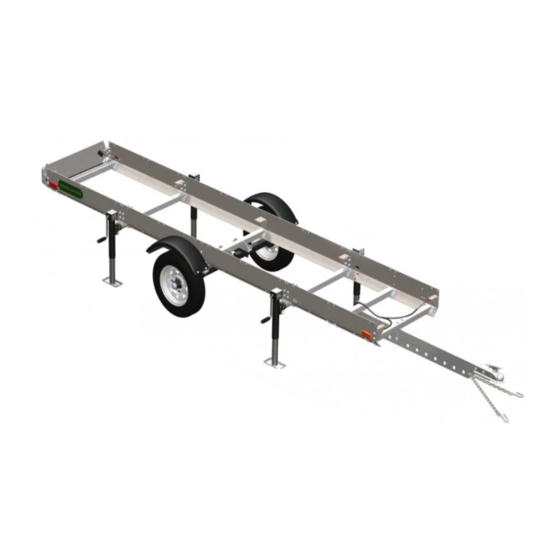
Sawmill trailer
Hide thumbs
Also See for Woodlander:
- Operator's manual (72 pages) ,
- Operator's manual (48 pages) ,
- Operator's manual (68 pages)

Related Manuals for Woodland Mills Woodlander


Summary of Contents for Woodland Mills Woodlander
- Page 1 WOODLANDER SAWMILL TRAILER ™ OPERATOR’S MANUAL The Woodlander ™ is compatible with HM126 and HM130 sawmills. Woodlander ™ is a trademark of Woodland Mills, Inc.
- Page 2 This page intentionally left blank.
-
Page 3: Table Of Contents
Woodlander ™ Operator’s Manual TABLE OF CONTENTS TABLE OF CONTENTS ___________________________________ INTRODUCTION _________________________________________ GENERAL SAFETY RULES _______________________________ INSPECTION/MAINTENANCE ______________________________ TECHNICAL SPECIFICATIONS ____________________________ BOLT TORQUE SPECIFICATIONS ____________________________ TRAILER ASSEMBLY ____________________________________ 1. TOOLS REQUIRED _____________________________________ 2. UNPACKING ___________________________________________ 3. GUSSETS _____________________________________________ 4. SIDE PLATES _________________________________________ 5. - Page 4 Woodlander ™ Operator’s Manual TONGUE _______________________________________________ NORTH AMERICA ________________________________________________ EUROPE ________________________________________________________ AXLES, WHEELS, AND FENDERS ___________________________ LIGHTING _______________________________________________ NORTH AMERICA ________________________________________________ EUROPE ________________________________________________________ BADGES ________________________________________________ HEAD LOCK-DOWN BRACKETS ____________________________ NOTES _______________________________________________ HM126T-MY2019: Rev B Page 04-Dec-2018...
-
Page 5: Introduction
If you have any questions relative to a particular application, DO NOT use the trailer until you have first contacted Woodland Mills to determine if it can or should be performed using the product. -
Page 6: General Safety Rules
Woodlander ™ Operator’s Manual **SAVE THESE INSTRUCTIONS** GENERAL SAFETY RULES WARNING! Read and understand all instructions. Failure to follow all instructions listed below may result serious injury. WARNING! The warnings, cautions, and instructions discussed in this instruction manual cannot cover all possible conditions or situations that could occur. -
Page 7: Technical Specifications
Woodlander ™ Operator’s Manual TECHNICAL SPECIFICATIONS Item Specification Trailer Axle Independent Torsion Axle Design Trailer Wheels 5 Bolts @ 4.5” (114 mm) & 5.30-12 DOT Approved Tires Tire Pressure Refer to Tire Wheel Nut Torque 80 ft•lb / 110 N•m Trailer Ball Coupler 2”... -
Page 8: Trailer Assembly
Woodlander ™ Operator’s Manual TRAILER ASSEMBLY 1. TOOLS REQUIRED Tool Specification Phillips Head Screwdriver No. 3 Assembly Wrench/Socket 8 mm Assembly Wrench/Socket 9 mm Assembly Wrench/Socket 10 mm Assembly Wrench/Socket 13 mm Assembly Wrench/Socket 14 mm Assembly Wrench/Socket 15 mm... -
Page 9: Unpacking
Woodlander ™ Operator’s Manual 2. UNPACKING Remove all the parts from the steel crate. Set the crate aside as it will be used as a support for several of the following steps. HM126T-MY2019: Rev B Page 04-Dec-2018... -
Page 10: Gussets
Woodlander ™ Operator’s Manual 3. GUSSETS Using the hardware listed below, assemble the gussets to the track as shown on the next page. Ensure the track is 30.5” (775 mm) wide, measuring diagonally to check for squareness. Torque all bolts per the table in section BOLT TORQUE SPECIFICATIONS. - Page 11 Woodlander ™ Operator’s Manual End Bunk M10 x 30 mm Middle Bunk M10 Lock Nut M10 x 30 mm Joining Bunk End Gusset M10 Lock Nut M10 x 30 mm Middle Bunk Joining Gusset M10 x 40 mm M10 x 30 mm...
-
Page 12: Side Plates
Woodlander ™ Operator’s Manual 4. SIDE PLATES Place the track/gusset assembly on top of the shipping crate, ensuring it is centred end-to-end. Using the hardware listed below, hang the side plates using the M10 X 30 mm and M10 X 35 mm bolts. - Page 13 Woodlander ™ Operator’s Manual M10 X 35 mm at Carriage Stops M10 X 30 mm M10 X 30 mm at all other at all other locations locations HM126T-MY2019: Rev B Page 04-Dec-2018...
-
Page 14: Front And Rear Cross Beams
Woodlander ™ Operator’s Manual 5. FRONT AND REAR CROSS BEAMS Using the hardware listed below, install the front and rear cross beams (2 front, 1 rear). Ensure the cross beam with the two holes is assembled at the front. Do not tighten these bolts. - Page 15 Woodlander ™ Operator’s Manual Front Cross Beam Cross Beam Cross Beam HM126T-MY2019: Rev B Page 04-Dec-2018...
-
Page 16: Bolt Torquing And Jack Stands
Woodlander ™ Operator’s Manual 6. BOLT TORQUING AND JACK STANDS Torque all bolts per the table in section, BOLT TORQUE SPECIFICATIONS, starting from the centre and working towards the outer ends. Ensure the track is straight, level, and square during this procedure. -
Page 17: Inner Cross Beams And Jack Mounts
Woodlander ™ Operator’s Manual 7. INNER CROSS BEAMS AND JACK MOUNTS Using the hardware listed below, install the 2 remaining cross beams and 4 jack mounts. Torque all the bolts per the table in section BOLT TORQUE SPECIFICATIONS. M10 X 35 mm... - Page 18 Woodlander ™ Operator’s Manual HM126T-MY2019: Rev B Page 04-Dec-2018...
- Page 19 Woodlander ™ Operator’s Manual Next, lower the trailer onto the crate and remove the jacks. Slide the jacks onto the jack mounts and secure them with the pin chained to the jack. Raise the jacks up to slide the crate out from under the trailer assembly.
-
Page 20: Axle Mounts And Axle Cross Beam
Woodlander ™ Operator’s Manual 8. AXLE MOUNTS AND AXLE CROSS BEAM Using the hardware listed below, install the axle mount cross beam and left/right axle mounts with fender adapter as shown. Tighten these bolts. M10 X 35 mm Axle Mount w/... - Page 21 Woodlander ™ Operator’s Manual HM126T-MY2019: Rev B Page 04-Dec-2018...
-
Page 22: Axles
Woodlander ™ Operator’s Manual 9. AXLES Using the hardware listed below, install the axles as shown on the next page. Tighten these bolts to the specified torque. Place a bubble level across both axles and check for level. If the level is off, use axle shim plates between the inner axle mounting face and axle cross beam to ensure the axles ride level. - Page 23 Woodlander ™ Operator’s Manual Install up to 3 shim plates per axle if necessary to level axles. Only use if axles require levelling. Axle swingarms point towards rear of trailer. HM126T-MY2019: Rev B Page 04-Dec-2018...
-
Page 24: Tongue And Coupler
Woodlander ™ Operator’s Manual 10. TONGUE AND COUPLER Using the hardware listed below, install the trailer tongue and hitch coupler. Don’t tighten the M10 X 160 mm bolts in this step since the plug for the lights will be routed through the tongue in the following step. - Page 25 Woodlander ™ Operator’s Manual Europe M12 X 100 mm North America M12 X 70 mm M10 X 160 mm Side plate removed for clarity. HM126T-MY2019: Rev B Page 04-Dec-2018...
-
Page 26: Lighting
Woodlander ™ Operator’s Manual 11. LIGHTING Using the hardware listed below, install the light bar and country appropriate wire harness. Secure tail lights to the light bar using M5 flanged lock nuts before mounting light bar to trailer. Use cable clamps to secure wire harness to side plates down right-side of trailer. Tighten all bolts. - Page 27 Woodlander ™ Operator’s Manual M5 X 20 mm Pan Head M5 Lock Nut M8 X 25 mm M5 X 20 mm Europe Only Pan Head Note: tail lights (North America and Europe) and side lights (North America only) are integral to the wire harness.
- Page 28 Woodlander ™ Operator’s Manual Europe Only Route wire harness through tongue prior to tightening M10 X 160 mm bolts M5 X 20 mm Pan Head M6 X 20 mm There are 2 cable clamps per short side plate (2) and 4 per long side plate (1) for a total of 8.
-
Page 29: Badges
Woodlander ™ Operator’s Manual 12. BADGES Using the hardware listed below, install the two (2) Woodlander badges as shown. M6 X 20 mm Hex Woodlander Bolt Badge M6 Flat Washer M6 Lock Nut HM126T-MY2019: Rev B Page 04-Dec-2018... - Page 30 Woodlander ™ Operator’s Manual HM126T-MY2019: Rev B Page 04-Dec-2018...
-
Page 31: Head Lock-Down Brackets
Woodlander ™ Operator’s Manual 13. HEAD LOCK-DOWN BRACKETS Place the assembled saw head on the trailer. Using the hardware listed below, install the head lock down brackets as shown on the next page. Tighten these bolts to the specified torque. - Page 32 Woodlander ™ Operator’s Manual Remove the spacers (4x) from in-between the side plates as shown. Using the provided M6 X 40 and M6 X 25 mm bolts, install the brackets in place of the spacers. Reuse the four (4) M6 flat washers from the wheel sweepers on the sawmill when replacing the bolts.
- Page 33 64.50 Woodlander ™ Operator’s Manual Drill four (4) holes for the lock-down brackets using the provided 3/8” drill bit. Measure 64.5” (164 cm) from the rear edge of the track rail (not the carriage stop) to the rear post of the saw head.
-
Page 34: Wheels
Woodlander ™ Operator’s Manual 14. WHEELS Using the hardware listed below, install the tires on the axles. Using a torque wrench, torque the lug nuts to 80 ft•lb / 110 N•m following the pattern shown below. 5.30-12 Wheel 1/2-20 Lug Nut... -
Page 35: Fenders
Woodlander ™ Operator’s Manual 15. FENDERS Using the hardware listed below, assemble the fenders to the fender brackets. Tighten these bolts. Slide the post on the fender bracket into the sleeve on the axle mount and insert the locking pin through the hole located at the bottom of the fender bracket post. Secure the fender/ fender bracket sub-assembly using the M10 X 30 mm knob by threading it into the axle mount until tight. - Page 36 Woodlander ™ Operator’s Manual Knob Some components removed for clarity HM126T-MY2019: Rev B Page 04-Dec-2018...
-
Page 37: Safety Chain
Woodlander ™ Operator’s Manual 16. SAFETY CHAIN Using the hardware below, install the safety chain on the trailer tongue. This step is not needed for European customers. M10 X 40 mm Safety Chain Hex Bolt (Not in (Not in Europe) -
Page 38: Parts List
0001390 REAR REFLECTOR, RED, EUROPE 0001391 SIDE REFLECTOR, AMBER, EUROPE 0001392 FRONT REFLECTOR, WHITE, EUROPE 0001886 WOODLANDER BADGE 0001683 BRACKET, METAL FENDER, 750/850 kg AXLE 0001684 FENDER, METAL 0001698 KNOB, MULTI-LOBE, 48 mm OD, M10 X 1.5, 30 mm LG... - Page 39 Woodlander ™ Operator’s Manual Item Part No. Description HEX BOLT, FLANGED, M12 X 1.75, 35 mm LG SCREW, PPH, M5 X 0.8, 20 mm LG FLAT WASHER, M6 FLAT WASHER, M10 LOCK NUT, M6 X 1 LOCK NUT, M10 X 1.5 LOCK NUT, M12 X 1.75...
-
Page 40: Exploded Assembly Views
Woodlander ™ Operator’s Manual EXPLODED ASSEMBLY VIEWS COMPLETE ASSEMBLY HM126T-MY2019: Rev B Page 04-Dec-2018... -
Page 41: Chassis And Track
Woodlander ™ Operator’s Manual CHASSIS AND TRACK HM126T-MY2019: Rev B Page 04-Dec-2018... -
Page 42: Tongue
Woodlander ™ Operator’s Manual TONGUE NORTH AMERICA 50 2X 52 2X EUROPE 50 2X 50 2X 52 2X 52 2X HM126T-MY2019: Rev B Page 04-Dec-2018... -
Page 43: Axles, Wheels, And Fenders
Woodlander ™ Operator’s Manual AXLES, WHEELS, AND FENDERS HM126T-MY2019: Rev B Page 04-Dec-2018... -
Page 44: Lighting
Woodlander ™ Operator’s Manual LIGHTING NORTH AMERICA 54 2X 54 2X 54 2X 43 4X 43 4X 43 4X HM126T-MY2019: Rev B Page 04-Dec-2018... -
Page 45: Europe
Woodlander ™ Operator’s Manual EUROPE 54 2X 43 4X HM126T-MY2019: Rev B Page 04-Dec-2018... -
Page 46: Badges
Woodlander ™ Operator’s Manual BADGES HM126T-MY2019: Rev B Page 04-Dec-2018... -
Page 47: Head Lock-Down Brackets
Woodlander ™ Operator’s Manual HEAD LOCK-DOWN BRACKETS HM126T-MY2019: Rev B Page 04-Dec-2018... -
Page 48: Notes
Woodlander ™ Operator’s Manual NOTES HM126T-MY2019: Rev B Page 04-Dec-2018... - Page 49 Woodlander ™ Operator’s Manual HM126T-MY2019: Rev B Page 04-Dec-2018...
- Page 50 Woodlander ™ Operator’s Manual HM126T-MY2019: Rev B Page 04-Dec-2018...
- Page 51 This page intentionally left blank.
Need help?
Do you have a question about the Woodlander and is the answer not in the manual?
Questions and answers