
Related Manuals for Woodland Mills MULTILANDER TRAILER


Summary of Contents for Woodland Mills MULTILANDER TRAILER
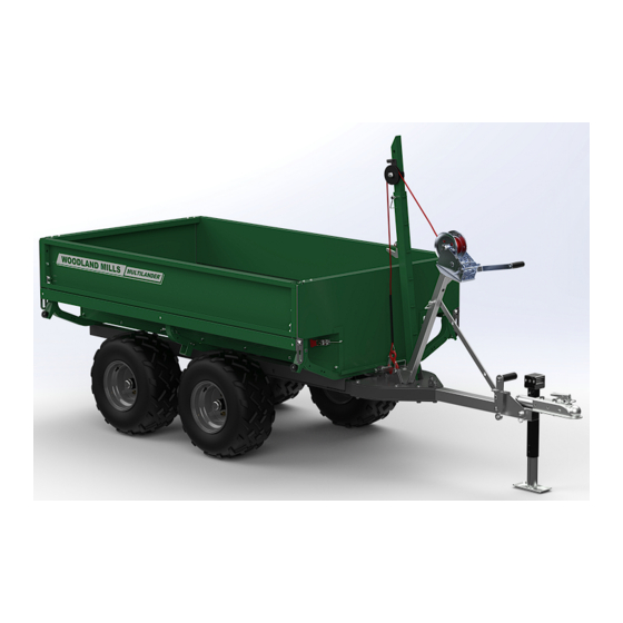
- Page 1 MULTILANDER TRAILER ™ OPERATOR’S MANUAL Multilander ™ is a trademark of Woodland Mills, Inc.
- Page 2 This page intentionally left blank.
-
Page 3: Table Of Contents
Multilander ™ Operator’s Manual TABLE OF CONTENTS TABLE OF CONTENTS __________________________________________________1 INTRODUCTION ________________________________________________________3 GENERAL SAFETY RULES_______________________________________________4 INSPECTION/MAINTENANCE _____________________________________________4 TECHNICAL SPECIFICATIONS ____________________________________________5 OVERALL DIMENSIONS ______________________________________________6 COMPONENT LISTS ____________________________________________________7 TO-SCALE HARDWARE _______________________________________________9 BOLTS & SCREWS __________________________________________________9 SCALES __________________________________________________________11 WASHERS ________________________________________________________12 NUTS _____________________________________________________________13 TOOLS REQUIRED ____________________________________________________14 BOLT TORQUE________________________________________________________15 CHASSIS ASSEMBLY __________________________________________________16... - Page 4 Multilander ™ Operator’s Manual WINCH AND BOOM ASSEMBLY __________________________________________41 1. WINCH POST ___________________________________________________41 2. BOOM _________________________________________________________43 3. WINCH ROPE ___________________________________________________45 OPERATION __________________________________________________________46 MAINTENANCE _______________________________________________________52 GREASE POINTS ___________________________________________________52 REPLACEMENT PARTS ORDERING ______________________________________53 EXPLODED ASSEMBLY VIEWS __________________________________________54 CHASSIS__________________________________________________________54 WHEELS __________________________________________________________55 WINCH ___________________________________________________________56 BOOM &...
-
Page 5: Introduction
If you have any questions relative to a particular application, DO NOT use the trailer until you have first contacted Woodland Mills to determine if it can or should be performed using the product. -
Page 6: General Safety Rules
Multilander ™ Operator’s Manual **SAVE THESE INSTRUCTIONS** GENERAL SAFETY RULES WARNING! Read and understand all instructions. Failure to follow all instructions listed below may result serious injury. WARNING! The warnings, cautions, and instructions discussed in this instruction manual cannot cover all possible conditions or situations that could occur. -
Page 7: Technical Specifications
Multilander ™ Operator’s Manual TECHNICAL SPECIFICATIONS Item Specification Construction/Finish Powder-Coated/Galvanized Tube & Plate Steel Axle Walking Beam Wheels & Tires 4 Bolts @ 4” [101.6 mm] & 23x10.5-12 Tires Tire Pressure Refer to Tire Wheel Nut Torque 80 ft•lb [110 N•m] Trailer Ball Coupler 2 in [50 mm] Hauling Capacity 2000 lb [907 kg] Log Winch Capacity 2000 lb [907 kg]... -
Page 8: Overall Dimensions
Multilander ™ Operator’s Manual OVERALL DIMENSIONS 0008127-M-EN: Rev B Page 24-Feb-2023... -
Page 9: Component Lists
Multilander ™ Operator’s Manual COMPONENT LISTS Verify all component and hardware quantities are correct prior to assembling the trailer. Right Wheel Chassis Side [22X11-10R] Rail Left Wheel [0008131] [22X11-10L] Swivel Jack Tongue Mount [0008135] [0002249] Bottom Tongue Swivel Jack Plate Handle Mount [0008134] [0008314]... - Page 10 Multilander ™ Operator’s Manual Left Lower Side Panel Beam [0008709] [0008138] Right Lower Side Panel Beam Hinge [0008137] [0008699] Support Rib Indexer [0007156] [0008706] Spacer Bed Panel 10 X 16 X 8 [0007124] [0008711] Stepped Side Hook Latch Panel [0002338] [0007126] Hinge Block Tailgate...
-
Page 11: To-Scale Hardware
Multilander ™ Operator’s Manual *The Ramp Storage Bracket Assemblies Winch and may ship assembled to the Log Loading Rope Assembly Ramp Leg in the crate. TO-SCALE HARDWARE BOLTS & SCREWS Hardware graphics are printed at 1:1 scale for ease of identification. Simply place the hardware over the image in the tables to verify it is the correct size. - Page 12 Multilander ™ Operator’s Manual HHB-MBR090FCJ M12 X 1.75 X 35 mm HEX BOLT HHB-MBR130PCJ M12 X 1.75 X 75 mm HEX BOLT HHB-MBR145PCJ M12 X 1.75 X 90 mm HEX BOLT BHS-MBE063FCM M6 X 1 X 12 mm BUTTON HEAD SCREW BHS-MBE135FCM M6 X 1 X 80 mm BUTTON HEAD SCREW BHS-MBJ067FCM...
-
Page 13: Scales
Multilander ™ Operator’s Manual BHS-MBJ155FCM M8 X 1.25 X 100 mm BUTTON HEAD SCREW BHS-MBM110PCM M10 X 1.5 X 55 mm BUTTON HEAD SCREW BHS-MBM115PCM M10 X 1.5 X 60 mm BUTTON HEAD SCREW HFH-MBM115PCM M10 X 1.5 X 60 mm FLAT HEAD SCREW HFH-MBM125PCM M10 X 1.5 X 70 mm FLAT HEAD SCREW SCALES... -
Page 14: Washers
Multilander ™ Operator’s Manual WASHERS FTW-MBE000AJ FTW-MBJ000AJ M6 FLAT WASHER M8 FLAT WASHER FTW-MBM000AJ FTW-MBR000AJ M10 FLAT WASHER M12 FLAT WASHER FTW-MCC000AJ FDW-MBM083000AJ M18 FLAT WASHER M10 X 34 mm FENDER WASHER 0008127-M-EN: Rev B Page 24-Feb-2023... -
Page 15: Nuts
Multilander ™ Operator’s Manual NUTS HLN-MBECH HLN-MBJCH M6 X 1 LOCK NUT M8 X 1.25 LOCK NUT HLN-MBMCH HLN-MBRCH M10 X 1.5 LOCK NUT M12 X 1.75 LOCK NUT HLN-MCCCH 0006202 M18 X 2.5 LOCK NUT* M12 X 1.5 LUG NUT 0006092 M24 X 1.5 SLOTTED LOCK NUT 0008127-M-EN: Rev B... -
Page 16: Tools Required
Multilander ™ Operator’s Manual TOOLS REQUIRED Tool Specification Wrench/Socket 10 mm Wrench/Socket 13 mm Wrench/Socket 16 mm Wrench/Socket 17 mm Wrench/Socket 18 mm Wrench/Socket 19 mm Wrench/Socket 27 mm Adjustable Wrench Variable Hex Key 4 mm Hex Key 5 mm Pliers Needle Nose, Lineman’s, or Slip-Joint Torque Wrench... -
Page 17: Bolt Torque
Multilander ™ Operator’s Manual BOLT TORQUE BOLT TORQUE WARNING! When assembling the trailer, do not torque the bolts to hardware Class/Grade specifications. Snug the hardware, then tighten a further ¼—½ turn. Tightening bolts to torque spec can crush metal tubing, ruining the components. -
Page 18: Chassis Assembly
Multilander ™ Operator’s Manual CHASSIS ASSEMBLY 1. FRAME Using the components and hardware listed below, assemble the chassis side rails to the tongue . M12 X 90 mm Chassis Side Hex Bolt Rail M12 Flat Tongue Washer Bottom Tongue M12 Lock Nut Plate Top Tongue Plate... -
Page 19: Tongue Orientation
Multilander ™ Operator’s Manual TONGUE ORIENTATION When the hitch ball coupler is assembled to the tongue in a later step, it will become a 360° rotating ball hitch (see right). The tongue can be used with the hitch ball coupler positioned above the tongue or below the tongue (see graphics below). - Page 20 Multilander ™ Operator’s Manual Lay out the side rails and tongue on a flat surface. It can be beneficial to the assembly process to build the chassis on blocks or timbers. Use eight (8) M12 X 90 mm hex bolts, fifteen (15) M12 flat washers, eight (8) M12 lock nuts and the Brace Storage Bracket to sandwich the rails and tongue between the top and bottom tongue plates.
-
Page 21: Axle Cross Beam
Multilander ™ Operator’s Manual 2. AXLE CROSS BEAM Using the components and hardware listed below, assemble the axle cross beam to the chassis side beams. M12 X 90 mm Axle Cross Hex Bolt Beam M12 Flat Washer M12 Lock Nut Use four (4) M12 X 90 mm hex bolts, eight (8) M12 flat washers, and four (4) M12 lock nuts to join the axle cross beam to the side rails. -
Page 22: Walking Beams
Multilander ™ Operator’s Manual 3. WALKING BEAMS Using the components and hardware listed below, assemble the walking beams to the axle cross beam. Nylon Spacer 30.5 ID X 50 Cotter Pin OD X 3 mm Spacer Walking Beam 24.5 ID X 50 Assembly OD X 4 mm M24 Slotted... -
Page 23: Wheels
Multilander ™ Operator’s Manual 4. WHEELS Using the hardware listed below, assemble the wheels to the walking beam hubs. Right Wheel M12 Lug Nut Left Wheel Ensure the wheels are oriented so that the tread pattern faces the correct direction. Install the wheels to the walking beams and torque all the lug nuts to 80 ft•lb. -
Page 24: Swivel Jack
Multilander ™ Operator’s Manual 5. SWIVEL JACK Using the components and hardware listed below, assemble the jack mount to the tongue. M12 X 35 mm Swivel Jack Hex Bolt Mount M10 X 90 mm Swivel Jack Hex Bolt Handle Mount M12 Flat Swivel Jack Washer... - Page 25 Multilander ™ Operator’s Manual Next, using one (1) M12 X 35 mm hex bolt, three (3) M12 flat washers, and one (1) M12 lock nut, secure the winch brace to the jack handle mount as shown. Tighten the nut enough so that the brace will still rotate freely but not come loose.
-
Page 26: Coupler
Multilander ™ Operator’s Manual 6. COUPLER Using the components and hardware listed below, assemble the hitch ball coupler to the rotating hitch on the tongue. M12 X 75 mm Hitch Ball Hex Bolt Coupler M12 Flat Round Locking Washer M12 Lock Nut Use two (2) M12 X 75 mm hex bolts, four (4) M12 flat washers, and two (2) M12 lock nuts to secure the hitch ball coupler to the rotating hitch on the tongue. -
Page 27: Bumpers
Multilander ™ Operator’s Manual 7. BUMPERS Using the components and hardware listed below, assemble the bumpers to the side rails. M6 X 80 mm Rubber Button Head Bumper Screw M6 Flat Washer M6 Lock Nut Use one (1) M6 X 80 mm button head screw, two (2) M6 flat washers, and one (1) M6 lock nut to secure each bumper to both side rails. -
Page 28: Utility Box Assembly
Multilander ™ Operator’s Manual UTILITY BOX ASSEMBLY 1. FRAME Using the components and hardware listed below, assemble the utility box frame. M10 X 55 mm Left Lower Button Head Beam Screw M8 X 60 mm Right Lower Button Head Beam Screw M10 Flat Support Rib... - Page 29 Multilander ™ Operator’s Manual Use twelve (12) M8 X 60 mm button head screws, twelve (12) M8 flat washers, and twelve (12) M8 lock nuts to assemble the bed panel, support ribs, and lower beams together. Use two (2) M10 X 55 mm button head screws, two (2) M10 flat washers, and two (2) M10 lock nuts in the two centre holes at the rear of the bed pan where noted.
-
Page 30: Stepped Sides
Multilander ™ Operator’s Manual 2. STEPPED SIDES Using the components and hardware listed below, assemble the stepped side panels to the utility box frame. M8 X 14 mm Stepped Side Button Head Panel Screw M8 Flat Washer M8 Lock Nut Use seven (7) M8 X 14 mm button head screws, seven (7) M8 flat washers, and seven (7) M8 lock nuts to join each stepped side panel to the bed panel. - Page 31 Multilander ™ Operator’s Manual With the stepped side panels loosely assembled, use the following components and hardware to finalize their assembly to the utility box frame. M8 X 100 mm Button Head Hinge Block Screw M8 Flat Spacer Washer 8 X 12 X 48 M8 Lock Nut Use one (1) M8 X 100 mm button head screw, one (1) M8 flat washer, and one (1) M8 lock nut to join each hinge block at both ends of each stepped side panel with the two end support ribs.
- Page 32 Multilander ™ Operator’s Manual Hinge Block Detail Spacer Detail Threaded hole in Spacer is positioned hinge block facing inside the lip edge outward. of the stepped side panel. Slot in hinge block needs to be fully inside the stepped side panel slot when the hardware is tightened.
-
Page 33: Pickup
Multilander ™ Operator’s Manual 3. PICKUP Using the components and hardware listed below, assemble the pickup to the bed frame. M10 X 60 mm Button Head Pickup Screw M10 Flat Washer M10 Lock Nut Use two (2) M10 X 60 mm button head screws, two (2) M10 flat washers, and two (2) M10 lock nuts to secure the pickup to the front support rib. -
Page 34: Utility Box-To-Chassis
Multilander ™ Operator’s Manual 4. UTILITY BOX-TO-CHASSIS Using the components and hardware listed below, assemble the utility box to the chassis. M18 X 120 mm M18 Lock Nut Hex Head Bolt M18 Flat Square Washer Locking Pin Use two (2) M18 X 120 mm hex head bolts, four (4) M18 flat washers, and two (2) M18 lock nuts to secure the pickup to the front support rib. -
Page 35: Bracketry
Multilander ™ Operator’s Manual 5. BRACKETRY Using the components and hardware listed below, assemble the brackets to the utility box support ribs. Bumper M8 X 70 mm Bracket Hex Head Bolt Assembly Ramp Storage M8 X 65 mm Bracket Hex Head Bolt Assembly* M8 X 60 mm Winch Bracket... - Page 36 Multilander ™ Operator’s Manual At the left-rear corner, assemble the bumper and ramp storage bracket to the support rib using one (1) M8 X 70 mm hex head bolt, two (2) M8 flat washers, and one (1) M8 lock nut. For the remaining three corners, use the same hardware except replace the M8 X 70 mm hex head bolt with the 65 mm long bolt.
- Page 37 Multilander ™ Operator’s Manual It is important when installing the front storage bracket that it be oriented opposite the bracket in the left-rear corner as shown below, otherwise, the holes in the ramp leg will not align with the bracket posts when stowed. Front storage Left-rear bracket...
-
Page 38: Side Panels
Multilander ™ Operator’s Manual 6. SIDE PANELS Using the components and hardware listed below, assemble the side panels and secure them to the utility box. M10 X 70 mm Flat Head M10 Lock Nut Screw M10 X 60 mm Flat Head Side Panel Screw M10 X 25 mm... - Page 39 Multilander ™ Operator’s Manual Assemble both side panels to the utility box bed, ensuring the indexers slide down into the slots in the hinge blocks. On both ends of each side panel, secure the panel to the bed. Thread one (1) M10 X 25 mm hex head bolt, one (1) M10 fender washer, and one (1) spacer through the side panel hinge slot and into the threaded hole in the hinge block as shown below.
-
Page 40: Tailgates
Multilander ™ Operator’s Manual 7. TAILGATES Using the components and hardware listed below, assemble the tailgates to the utility box. M6 X 12 mm Button Head Hook Latch Screw Tailgate M6 Lock Nut Assembly Use two (2) M6 X 12 mm button head screws and two (2) M6 lock nuts to secure each of the four (4) hook latches to the stepped side panels as shown. - Page 41 Multilander ™ Operator’s Manual Slide the tailgates down so that the tailgate pins nest into the slots at the top of the side panel tubes. Tailgate Pin Then secure the tailgates to the utility box with the hook latches. Adjust the engagement of the hook latches using the jam nut on the latch.
-
Page 42: Log Loading Ramp Leg
Multilander ™ Operator’s Manual 8. LOG LOADING RAMP LEG Use the components listed below to store the log loading ramp leg up under the stepped side panel. Hairpin Cotter Log Loading [2x] Ramp Leg Remove the two (2) cotter pins from the ramp storage brackets if they are not already. Slide the log loading ramp leg onto the bracket posts through the hole and slot at each end of the leg. -
Page 43: Winch And Boom Assembly
Multilander ™ Operator’s Manual WINCH AND BOOM ASSEMBLY 1. WINCH POST Using the components and hardware listed below, assemble the winch post and install it on the trailer. M10 X 25 mm Hex Head Bolt M10 Flat Washer M10 Lock Nut Winch Post Winch Assembly... - Page 44 Multilander ™ Operator’s Manual With the winch post assembled, slide the bent end of the post into the slot in the top tongue plate as shown. Insert the square locking pin to keep it from backing out. Square Locking Pin Rotate winch brace up Disconnect the square locking pin from the winch brace, rotate the brace up, and reinstall the...
-
Page 45: Boom
Multilander ™ Operator’s Manual 2. BOOM Using the components and hardware listed below, assemble the boom to the trailer. Boom Clevis Pin Assembly Hairpin Cotter The boom comes assembled in the crate. Ensure all the fasteners are tight before installing the boom on the trailer. - Page 46 Multilander ™ Operator’s Manual Install the boom into the slot in the top tongue plate and secure it with the clevis pin and hairpin cotter pin. Rest the boom against the tailgate until the winch rope is routed. Secure boom with clevis pin and cotter pin 0008127-M-EN: Rev B...
-
Page 47: Winch Rope
Multilander ™ Operator’s Manual 3. WINCH ROPE Route the rope from the winch over the boom pulley. Slide the retainer up so that the rope can pass over the pulley then release it to let it back down. Connect the hook to the pickup on the front of the utility box. -
Page 48: Operation
Multilander ™ Operator’s Manual OPERATION To haul timber, the Multilander can be converted to a log loading configuration allowing for logs ™ to be winched up the side and into the bed. Follow the steps on the following pages to set up the trailer for log loading. 0008127-M-EN: Rev B Page 24-Feb-2023... - Page 49 Multilander ™ Operator’s Manual Remove locking pin to slide winch post out Remove cotter pin and clevis pin Store winch brace as shown 1. REMOVE THE WINCH AND WINCH POST. 2. REMOVE THE BOOM. 3. REMOVE THE PULLEY ASSEMBLY 4.
- Page 50 Multilander ™ Operator’s Manual Disengage all the hook latches 5. DISENGAGE ALL THE HOOK LATCHES AND REMOVE BOTH TAILGATES. Pull the side panel up until the indexers are clear of the stepped sides 6. LIFT THE SIDE PANEL UP UNTIL THE INDEXERS ARE CLEAR OF THE STEPPED SIDES… ...
- Page 51 Multilander ™ Operator’s Manual …THEN LOWER THE SIDE PANEL DOWN. Use the square locking pins to secure the boom and ramp leg to the side panel Extend boom end as required to ensure level log loading: Winch boom doubles remove locking pin, as a ramp leg extend/retract boom, (Can be installed on...
- Page 52 Multilander ™ Operator’s Manual Lock the winch in place with the locking pin 8. SLIDE THE WINCH POST ASSEMBLY INTO THE WINCH BRACKET BETWEEN THE TWO WHEELS AND LOCK IT IN PLACE WITH THE SQUARE LOCKING PIN. 0008127-M-EN: Rev B Page 24-Feb-2023...
- Page 53 Multilander ™ Operator’s Manual It is important to route the cable rope around a log as follows so that the log is rolled up the ramps and not dragged up the ramps. Lift up side panel to pass hook through and set it back down The rope must route over and around the log and back up under the vertical side panel (lift the side panel up high enough to pass the hook through and set it back down on the rope).
-
Page 54: Maintenance
Multilander ™ Operator’s Manual MAINTENANCE GREASE POINTS The Multilander has seven (7) Zerk fitting grease points: one (1) on each wheel hub (4 total), two (2) on the walking beam pivots, and one (1) on the rotating hitch. Check each grease point prior to use and add grease as necessary. -
Page 55: Replacement Parts Ordering
Record the part number (e.g. 0001071, HHB-MBM080FCJ, etc.) from the “Part No.” column. Contact Woodland Mills through the website or via phone/email. If possible, include the invoice or sales number from the purchased product so an associated account can be located. If the account has multiple addresses on file, please indicate to which address the replacement... -
Page 56: Exploded Assembly Views
Multilander ™ Operator’s Manual EXPLODED ASSEMBLY VIEWS CHASSIS 0008127-M-EN: Rev B Page 24-Feb-2023... -
Page 57: Wheels
Multilander ™ Operator’s Manual WHEELS 0008127-M-EN: Rev B Page 24-Feb-2023... -
Page 58: Winch
Multilander ™ Operator’s Manual WINCH 0008127-M-EN: Rev B Page 24-Feb-2023... -
Page 59: Boom & Ramp Leg
Multilander ™ Operator’s Manual BOOM & RAMP LEG 0008127-M-EN: Rev B Page 24-Feb-2023... -
Page 60: Utility Box: Bed
Multilander ™ Operator’s Manual UTILITY BOX: BED 0008127-M-EN: Rev B Page 24-Feb-2023... -
Page 61: Utility Box: Bracketry
Multilander ™ Operator’s Manual UTILITY BOX: BRACKETRY 0008127-M-EN: Rev B Page 24-Feb-2023... -
Page 62: Utility Box: Side Panels
Multilander ™ Operator’s Manual UTILITY BOX: SIDE PANELS 0008127-M-EN: Rev B Page 24-Feb-2023... -
Page 63: Utility Box: Tailgates
Multilander ™ Operator’s Manual UTILITY BOX: TAILGATES 0008127-M-EN: Rev B Page 24-Feb-2023... -
Page 64: Parts List
Multilander ™ Operator’s Manual PARTS LIST Item Part No. Description 0008131 CHASSIS SIDE RAIL 0008135 TONGUE 0008134 TONGUE PLATE, BOTTOM 0008132 TONGUE PLATE, TOP 0008316 BRACE STORAGE BRACKET 0002249 JACK MOUNT, BUSHLANDER 0006798 SWIVEL JACK, PIPE MOUNT, SIDEWIND SOCKET RECEIVER 0008314 SWIVEL JACK HANDLE MOUNT 0008322... - Page 65 Multilander ™ Operator’s Manual Item Part No. Description 0001532 SYNTHETIC ROPE W/ 7/8-8 WLL2T HOOK, 30 ft [9.1 m] LG 0004369 LOG LOADING RAMP LEG 0008869 LOG LOADING RAMP LEG/BOOM 0004202 LOG LOADING RAMP LEG/BOOM INSERT 0004321 CLEVIS PIN, 16 mm DIA, 74 mm USABLE LG, 80 mm LG 0004706 COTTER PIN, HAIRPIN, 16-20 mm CLEVIS, 4 mm WIRE DIA 0004325...
-
Page 66: Notes
Multilander ™ Operator’s Manual NOTES 0008127-M-EN: Rev B Page 24-Feb-2023... - Page 67 This page intentionally left blank.
Need help?
Do you have a question about the MULTILANDER TRAILER and is the answer not in the manual?
Questions and answers