
Related Manuals for Woodland Mills WOODLANDER XL


Summary of Contents for Woodland Mills WOODLANDER XL
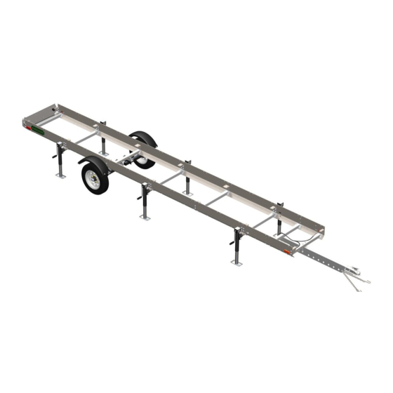
- Page 1 WOODLANDER XL SAWMILL TRAILER ™ OPERATOR’S MANUAL The Woodlander XL is compatible with HM126, HM130 & HM130MAX sawmills. Woodlander is a trademark of Woodland Mills, Inc. ™ ™...
- Page 2 This page intentionally left blank.
-
Page 3: Table Of Contents
2018-2022 Woodlander ™ XL Operator's Manual TABLE OF CONTENTS TABLE OF CONTENTS ___________________________________1 INTRODUCTION_________________________________________3 GENERAL SAFETY RULES _______________________________4 INSPECTION/MAINTENANCE______________________________4 TECHNICAL SPECIFICATIONS ____________________________5 BOLT TORQUE SPECIFICATIONS _____________________________5 TRAILER ASSEMBLY ____________________________________6 1. TOOLS REQUIRED ______________________________________6 2. UNPACKING ____________________________________________7 3. TRACK RAILS, JOINING GUSSETS, MID BUNK _______________8 4. - Page 4 2018-2022 Woodlander ™ XL Operator's Manual OPERATION ___________________________________________51 LOCKING-DOWN THE SAWMILL HEAD ________________________51 REPLACEMENT PARTS ORDERING _______________________53 EXPLODED ASSEMBLY VIEWS ___________________________54 CHASSIS AND TRACK______________________________________54 TONGUE_________________________________________________55 NORTH AMERICA _____________________________________________55 EUROPE ______________________________________________________55 AXLES, WHEELS, AND FENDERS ____________________________56 LIGHTING ________________________________________________57 NORTH AMERICA _____________________________________________57 EUROPE ______________________________________________________58 NAMEPLATES ____________________________________________59 JACKS __________________________________________________60...
-
Page 5: Introduction
If you have any questions relative to a particular application, DO NOT use the trailer until you have first contacted Woodland Mills to determine if it can or should be performed using the product. -
Page 6: General Safety Rules
2018-2022 Woodlander ™ XL Operator's Manual **SAVE THESE INSTRUCTIONS** GENERAL SAFETY RULES WARNING! Read and understand all instructions. Failure to follow all instructions listed below may result serious injury. WARNING! The warnings, cautions, and instructions discussed in this instruction manual cannot cover all possible conditions or situations that could occur. -
Page 7: Technical Specifications
Finish Powder Coat Paint / Galvanized Steel Fenders Removable Safety Locking pins and safety straps to secure sawhead while travelling Woodlander XL: 655 lb [297 kg] Shipping Weight Woodlander MAX XL: 820 lb [372 kg] Woodlander XL: 571 lb [259 kg]... -
Page 8: Trailer Assembly
2018-2022 Woodlander ™ XL Operator's Manual TRAILER ASSEMBLY 1. TOOLS REQUIRED Tool Specification Phillips Head Screwdriver No. 3 Wrench/Socket 8 mm Wrench/Socket 9 mm Wrench/Socket 10 mm Wrench/Socket 13 mm Wrench/Socket 14 mm Wrench/Socket 15 mm Wrench/Socket 18 mm Adjustable Wrench Variable Torque Wrench Capable of 93 ft•lb [126 N•m]... -
Page 9: Unpacking
2018-2022 Woodlander ™ XL Operator's Manual 2. UNPACKING Remove all the parts from the steel crate. Set the crate aside as it will be used as a support for several of the following steps. 0001709-M-EN: Rev B Page 01-Dec-2021... -
Page 10: Track Rails, Joining Gussets, Mid Bunk
2018-2022 Woodlander ™ XL Operator's Manual 3. TRACK RAILS, JOINING GUSSETS, MID BUNK Using the hardware listed below, assemble the gussets to the track as shown on the next page. Torque all bolts per the table in section BOLT TORQUE SPECIFICATIONS. M10 X 30 mm Flanged Hex Mid Bunk... - Page 11 2018-2022 Woodlander ™ XL Operator's Manual Using the shipping crate as an assembly aid, lay two (2) 2X4s across the top the crate near each end. Position the track/gusset assembly on the 2X4s, ensuring it is centred end-to-end. The 2X4s need to be long enough to support the track rails but shorter than the track is wide. Front Rear Note: bunk is oriented...
- Page 12 2018-2022 Woodlander ™ XL Operator's Manual Rear Front 0001709-M-EN: Rev B Page 01-Dec-2021...
-
Page 13: Long Side Plates, Joining Gussets
2018-2022 Woodlander ™ XL Operator's Manual 4. LONG SIDE PLATES, JOINING GUSSETS Using the hardware listed below, hang the long side plates on the centre track section. Snug the bolts up, but leave them loose enough to move the plates. M10 X 30 mm Long Side Flanged Hex... - Page 14 2018-2022 Woodlander ™ XL Operator's Manual 0001709-M-EN: Rev B Page 01-Dec-2021...
-
Page 15: Track Rails, End Bunks, End Gussets
2018-2022 Woodlander ™ XL Operator's Manual 5. TRACK RAILS, END BUNKS, END GUSSETS Using the hardware listed below, add the remaining track sections and end bunks. Leave the bolts loose. M10 X 30 mm Flanged Hex End Bunk Bolt M10 Flanged End Gusset Lock Nut Track Rail... - Page 16 2018-2022 Woodlander ™ XL Operator's Manual 0001709-M-EN: Rev B Page 01-Dec-2021...
-
Page 17: Jack Stands [Temporary]
2018-2022 Woodlander ™ XL Operator's Manual 6. JACK STANDS [TEMPORARY] Using 4 jack stands, place 2 under each end bunk and level the assembly while still using the crate as support in the middle. Measure diagonally to check for squareness. Tighten all of the vertical track rail bolts. -
Page 18: Centre Bunks
2018-2022 Woodlander ™ XL Operator's Manual 7. CENTRE BUNKS Using the hardware listed below, install the centre bunks to the track rails and joining gussets. Use eight (8) M10 X 40 mm bolts through each bunk. Tighten the bolts in the order instructed throughout this section. - Page 19 2018-2022 Woodlander ™ XL Operator's Manual Front Note: bunks are oriented with log support sleeves towards the front M10 X 40 mm through top, M10 lock nuts below gusset Rear 0001709-M-EN: Rev B Page 01-Dec-2021...
- Page 20 2018-2022 Woodlander ™ XL Operator's Manual Before torquing the side plate bolts shown through the remainder of this section, verify there is a ⅜-½ in [10-13 mm] uniform offset between the top of the track rails and the top of the side plates.
- Page 21 2018-2022 Woodlander ™ XL Operator's Manual Ensuring the side plate-to-rail offset is uniform, tighten and torque only the four (4) highlighted bolts securing the front long side plate. Do this for both sides of the trailer. With the front long side plate secured in place, note the gaps (if any) between the rear long side plate and the front long side plate.
- Page 22 2018-2022 Woodlander ™ XL Operator's Manual Attach the ratchet strap hooks to the lower outer edges the front and rear side plates and pull the sides plates together to help eliminate any gaps. Keep the strap in place until all the side plate bolts are torqued.
- Page 23 2018-2022 Woodlander ™ XL Operator's Manual While maintaining a uniform side plate-to-rail offset, torque the remaining bolts per the table in section, BOLT TORQUE SPECIFICATIONS, starting from the centre and working towards the outer ends. Ensure the track is straight, level, and square during this procedure. Remove ratchet strap after torquing bolts Remove the ratchet strap once all the bolts are tight.
-
Page 24: Mid Bunks, Joining Gussets
2018-2022 Woodlander ™ XL Operator's Manual 8. MID BUNKS, JOINING GUSSETS Using the hardware below, install the remaining bunks and gussets. Tighten the bolts in this step. M10 X 30 mm Flanged Hex Mid Bunk Bolt M10 Flanged Joining Gusset Lock Nut Rear Front... - Page 25 2018-2022 Woodlander ™ XL Operator's Manual Front Note: bunks are oriented with log support sleeves towards the front Rear 0001709-M-EN: Rev B Page 01-Dec-2021...
-
Page 26: Short Side Plates, Carriage Stops
2018-2022 Woodlander ™ XL Operator's Manual 9. SHORT SIDE PLATES, CARRIAGE STOPS Using the hardware listed below, install the short side plate and carriage stops. The M10 X 35 mm bolts are used at the 4 carriage stop locations. Tighten all of the side plate bolts only when instructed. - Page 27 2018-2022 Woodlander ™ XL Operator's Manual M10 X 30 mm through side. M10 X 35 mm at carriage stops. With the long side plates already secured in place, note the gaps (if any) between the short side plates and the long side plates. Track Rail Track Rail Uniform...
- Page 28 2018-2022 Woodlander ™ XL Operator's Manual Attach the ratchet strap hooks to the rectangular openings in the short side plates and pull the sides plates together to help eliminate any gaps. Keep the strap in place until all the bolts are torqued as outlined on the next page.
- Page 29 2018-2022 Woodlander ™ XL Operator's Manual While maintaining a uniform side plate-to-rail offset, torque the remaining bolts per the table in section, BOLT TORQUE SPECIFICATIONS, starting from the centre and working towards the outer ends. Ensure the track is straight, level, and square during this procedure. Remove ratchet strap after torquing bolts With all of the bolts now tightened, lower the jacks so that the assembly is resting entirely on the...
-
Page 30: Cross Beams, Jack Mounts [Ends]
2018-2022 Woodlander ™ XL Operator's Manual 10. CROSS BEAMS, JACK MOUNTS [ENDS] Using the hardware listed below, install the front and rear jack mounts including 1 cross beam with each pair of mounts. Tighten all bolts. Install jack stands on the jack mounts. M10 X 35 mm Flanged Hex Cross Beam... - Page 31 2018-2022 Woodlander ™ XL Operator's Manual 0001709-M-EN: Rev B Page 01-Dec-2021...
- Page 32 2018-2022 Woodlander ™ XL Operator's Manual Next, raise the assembly as high as the jacks stands will permit. Pull the crate out from under the assembly once it is sufficiently high enough. It may be necessary to place a block of wood under each jack foot to achieve a sufficient height.
-
Page 33: Cross Beam, Jack Mounts [Centre]
2018-2022 Woodlander ™ XL Operator's Manual 11. CROSS BEAM, JACK MOUNTS [CENTRE] Using the hardware below, install the centre cross beam and jack mounts. Level the trailer on all six jack stands. Tighten all the bolts. M10 X 35 mm Flanged Hex Cross Beam Bolt... - Page 34 2018-2022 Woodlander ™ XL Operator's Manual 0001709-M-EN: Rev B Page 01-Dec-2021...
-
Page 35: Cross Beams, Axle Cross Beam, Axle Mounts
2018-2022 Woodlander ™ XL Operator's Manual 12. CROSS BEAMS, AXLE CROSS BEAM, AXLE MOUNTS Using the hardware listed below, install the remaining cross beams, the front cross beam (with 2 holes), and axle mount cross beam in the locations shown below. Tighten all bolts. M10 X 35 mm Axle Mount w/ Flanged Hex... - Page 36 2018-2022 Woodlander ™ XL Operator's Manual Front Use M10 X 35 mm bolts for left and right axle mounts Left Axle Mount Right Axle Mount Note: Ensure sleeve is oriented Note: Ensure sleeve is oriented towards the rear of the trailer towards the rear of the trailer Thread knobs into Axle Mounts prior to bolting...
-
Page 37: Axles
2018-2022 Woodlander ™ XL Operator's Manual 13. AXLES Using the hardware listed below, install the axles as shown on the next page. Tighten these bolts to the specified torque. Place a bubble level across both axles and check for level. If the level is off, use axle shim plates between the inner axle mounting face and axle cross beam to ensure the axles ride level. - Page 38 2018-2022 Woodlander ™ XL Operator's Manual Install up to 3 shim plates Front per axle if necessary to level axles. Only use if axles require levelling. Axle swingarms point towards rear of trailer. Rear 0001709-M-EN: Rev B Page 01-Dec-2021...
-
Page 39: Wheels
2018-2022 Woodlander ™ XL Operator's Manual 14. WHEELS Using the hardware listed below, install the wheels on the axles. Using a torque wrench, torque the lug nuts to 80 ft•lb / 110 N•m following the pattern shown below. 5.30-12 Wheel 1/2-20 in Lug Nut Front Rear... -
Page 40: Fenders
2018-2022 Woodlander ™ XL Operator's Manual 15. FENDERS Using the hardware listed below, assemble the fenders to the fender brackets. Tighten these bolts. Slide the post on the fender bracket into the sleeve on the axle mount and insert the locking pin through the hole located at the bottom of the fender bracket post. - Page 41 2018-2022 Woodlander ™ XL Operator's Manual Some components removed for clarity 0001709-M-EN: Rev B Page 01-Dec-2021...
-
Page 42: Tongue, Hitch Coupler
2018-2022 Woodlander ™ XL Operator's Manual 16. TONGUE, HITCH COUPLER Using the hardware listed below, install the trailer tongue and hitch coupler. Don’t tighten the M10 X 160 mm bolts in this step since the plug for the lights will be routed through the tongue in the following step. - Page 43 2018-2022 Woodlander ™ XL Operator's Manual Europe M12 X 100 mm North America M12 X 70 mm M10 X 160 mm Side plate removed for clarity. 0001709-M-EN: Rev B Page 01-Dec-2021...
-
Page 44: Lighting
2018-2022 Woodlander ™ XL Operator's Manual 17. LIGHTING Using the hardware listed below, install the taillight bracket and country appropriate wire harness. Secure tail lights to the taillight bracket using M5 flanged lock nuts before mounting the taillight bracket to trailer. Use cable clamps to secure wire harness to side plates down right-side of trailer. - Page 45 2018-2022 Woodlander ™ XL Operator's Manual Cable Clamp locations (12X) M5 X 20 mm Pan Head M5 Lock Nut (Included with wiring harness) M5 Lock Nut M8 X 25 mm M5 X 20 mm Europe Only Pan Head Note: tail lights (North America and Europe) and side lights (North America only) are integral to the wire harness.
- Page 46 2018-2022 Woodlander ™ XL Operator's Manual Europe Only M5 Lock Nut Route wire harness through tongue prior to tightening M10 X 160 mm bolts M5 X 20 mm Pan Head M6 X 20 mm There are 2 cable clamps per short side plate (2) and 4 per long side plate (2) for a total of 12. Cable clamps are installed down the right-hand side of the trailer only.
-
Page 47: Nameplate
2018-2022 Woodlander ™ XL Operator's Manual 18. NAMEPLATE Using the hardware listed below, install the two (2) Woodlander nameplates as shown. M6 X 20 mm Hex Woodlander Bolt Nameplate M6 Flat Washer M6 Lock Nut 0001709-M-EN: Rev B Page 01-Dec-2021... - Page 48 2018-2022 Woodlander ™ XL Operator's Manual 0001709-M-EN: Rev B Page 01-Dec-2021...
-
Page 49: Safety Chain
2018-2022 Woodlander ™ XL Operator's Manual 19. SAFETY CHAIN Using the hardware below, install the safety chain on the trailer tongue. M10 X 40 mm Safety Chain Hex Bolt M10 Flat Washer M10 Lock Nut 0001709-M-EN: Rev B Page 01-Dec-2021... -
Page 50: Head Lock-Down Plates
2018-2022 Woodlander ™ XL Operator's Manual 20. HEAD LOCK-DOWN PLATES Place the assembled sawhead on the trailer. Using the hardware listed below, install the head lock down plates as shown on the next page. Tighten these bolts to the specified torque. M6 X 40 mm Hex Bolt M6 X 25 mm... - Page 51 2018-2022 Woodlander ™ XL Operator's Manual Remove the eight (8) spacers from the carriage wheel axles and discard the four (4) short spacers. Only the four (4) tall spacers will be reused in the next steps. Discard short spacers Using the provided M6 X 40 mm and M6 X 25 mm bolts, install the lock-down plates in place of the short spacers with the taller spacer sandwiched between.
- Page 52 2018-2022 Woodlander ™ XL Operator's Manual Drill four (4) holes for the lock-down plates using the provided 10 mm drill bit. Measure 19 in [48 cm] from the rear edge of the track rail (not the carriage stop) to the rear post of the sawhead. Insert a locking pin into each hole as they are drilled.
-
Page 53: Operation
2018-2022 Woodlander ™ XL Operator's Manual OPERATION LOCKING-DOWN THE SAWMILL HEAD When transporting the trailer, it is imperative that the sawmill head is locked-down securely to the trailer. Start by inserting the four (4) locking pins through the lock-down brackets and secure them with linch pins. - Page 54 2018-2022 Woodlander ™ XL Operator's Manual Lower the sawhead to its lowest position. Then insert the short strap hook into the cross beam lifting eye on one side of the sawmill, route the long strap down and under the bottom of the trailer, then up to the opposite lifting eye.
-
Page 55: Replacement Parts Ordering
Next, turn to the Parts Lists section and locate the balloon number in the “Item” column: Record the part number (e.g. 0001071, HHB-MBM080FCJ, etc.) in the “Part No.” column. Contact Woodland Mills through the website (or via phone/email) and provide the list of part numbers, including quantities for each item. -
Page 56: Exploded Assembly Views
2018-2022 Woodlander ™ XL Operator's Manual EXPLODED ASSEMBLY VIEWS CHASSIS AND TRACK 0001709-M-EN: Rev B Page 01-Dec-2021... -
Page 57: Tongue
2018-2022 Woodlander ™ XL Operator's Manual TONGUE NORTH AMERICA EUROPE 0001709-M-EN: Rev B Page 01-Dec-2021... -
Page 58: Axles, Wheels, And Fenders
2018-2022 Woodlander ™ XL Operator's Manual AXLES, WHEELS, AND FENDERS 0001709-M-EN: Rev B Page 01-Dec-2021... -
Page 59: Lighting
2018-2022 Woodlander ™ XL Operator's Manual LIGHTING NORTH AMERICA 0001709-M-EN: Rev B Page 01-Dec-2021... -
Page 60: Europe
2018-2022 Woodlander ™ XL Operator's Manual EUROPE 0001709-M-EN: Rev B Page 01-Dec-2021... -
Page 61: Nameplates
2018-2022 Woodlander ™ XL Operator's Manual NAMEPLATES 0001709-M-EN: Rev B Page 01-Dec-2021... -
Page 62: Jacks
2018-2022 Woodlander ™ XL Operator's Manual JACKS 0001709-M-EN: Rev B Page 01-Dec-2021... -
Page 63: Head Lock-Down
2018-2022 Woodlander ™ XL Operator's Manual HEAD LOCK-DOWN 0001709-M-EN: Rev B Page 01-Dec-2021... -
Page 64: Parts Lists
2018-2022 Woodlander ™ XL Operator's Manual PARTS LISTS NORTH AMERICA Quantity Item Part No. Description HM126 HM130 HM130 0001373 GUSSET, END 0001374 GUSSET, JOINING 0001363 SIDE PLATE, LONG 0001364 SIDE PLATE, SHORT 0001369 CROSS BEAM 0002900 CROSS BEAM, WOODLANDER MAX 0001370 CROSS BEAM, FRONT 0002899... - Page 65 2018-2022 Woodlander ™ XL Operator's Manual Quantity Item Part No. Description HM126 HM130 HM130 L44649 ROLLER BEARING, TAPERED, 1-1/16 in SFT, 1-3/64 in HSG, .56 in WD HHB-MBE075FCJ HEX HEAD BOLT, CLS 8.8, M6 X 1, 20 mm LG, FULL HHB-MBE080FCJ HEX HEAD BOLT, CLS 8.8, M6 X 1, 25 mm LG, FULL HHB-MBE095FCJ...
-
Page 66: Europe
2018-2022 Woodlander ™ XL Operator's Manual EUROPE Quantity Item Part No. Description HM126 HM130 HM130 0001373 GUSSET, END 0001374 GUSSET, JOINING 0001363 SIDE PLATE, LONG 0001364 SIDE PLATE, SHORT 0001369 CROSS BEAM 0002900 CROSS BEAM, WOODLANDER MAX 0001370 CROSS BEAM, FRONT 0002899 CROSS BEAM, FRONT, WOODLANDER MAX 0001376... - Page 67 2018-2022 Woodlander ™ XL Operator's Manual Quantity Item Part No. Description HM126 HM130 HM130 0004742 DRILL BIT, 10 mm, JOBBERS LG 0005146 RATCHET STRAP, 50 mm WD, 4500 mm LG 5.30-12 WHEEL, 5.30-12 L44649 ROLLER BEARING, TAPERED, 1-1/16 in SFT, 1-3/64 in HSG, .56 in WD HHB-MBE075FCJ HEX HEAD BOLT, CLS 8.8, M6 X 1, 20 mm LG, FULL HHB-MBE080FCJ...
-
Page 68: Notes
2018-2022 Woodlander ™ XL Operator's Manual NOTES 0001709-M-EN: Rev B Page 01-Dec-2021... - Page 69 2018-2022 Woodlander ™ XL Operator's Manual 0001709-M-EN: Rev B Page 01-Dec-2021...
- Page 70 2018-2022 Woodlander ™ XL Operator's Manual 0001709-M-EN: Rev B Page 01-Dec-2021...
- Page 71 This page intentionally left blank.
Need help?
Do you have a question about the WOODLANDER XL and is the answer not in the manual?
Questions and answers